Back to the home page
Back to the previous page
Turning tapers on a lathe
Tapers have two main purposes. They may be ornamental or they may have a mechanical function. Sometimes they might be both.
Ornamental tapers
Many tapers are “ornamental”. They make the job look properly finished or they can just be convenient. In this case the angle of the taper is not critical. Even so some ornamental taper that do not appear to need to be accurate do in fact require far more accuracy than one might expect. An example of this is a taper used merely as an ornament, for example on a column. Though it might appear that the angle is not critical the diameter at the top of the column and the diameter at the bottom will only be right if the angle is right. On tapers where the ratio of width to length is high very small errors in the angle can be very significant.
Ornamental tapers are usually external only.
Some tapers that are ornamental might also be fluted. Making flutes on a conical surface is covered at :
Making flutes on a conical surface
Mechanical
From a mechanical point of view, tapers have a very important property. This is that if a male taper fits into a female taper then the axis of the male taper will automatically line up with the axis of the female taper. But this is only true if the angles of both tapers are the same.
A second important property is that as the angle of a pair of tapers gets smaller then there is a tendency for the two tapers to lock together. On the other hand if the angle is large enough the tapers will never lock together.
In some cases a taper pair might have a key to ensure one pair cannot rotate. ( I think the wheels on an Austin Seven are held on using tapers and keys. This is, of course, a cheap solution. A better quality car, such as, a Singer Senior would use splines.)
Because of these features tapers are used extensively in engineering. Naturally it then becomes essential that there are standards for the sizes of tapers. Unfortunately there are quite a few sets of standards. One of the most common ones are those that define Morse tapers.
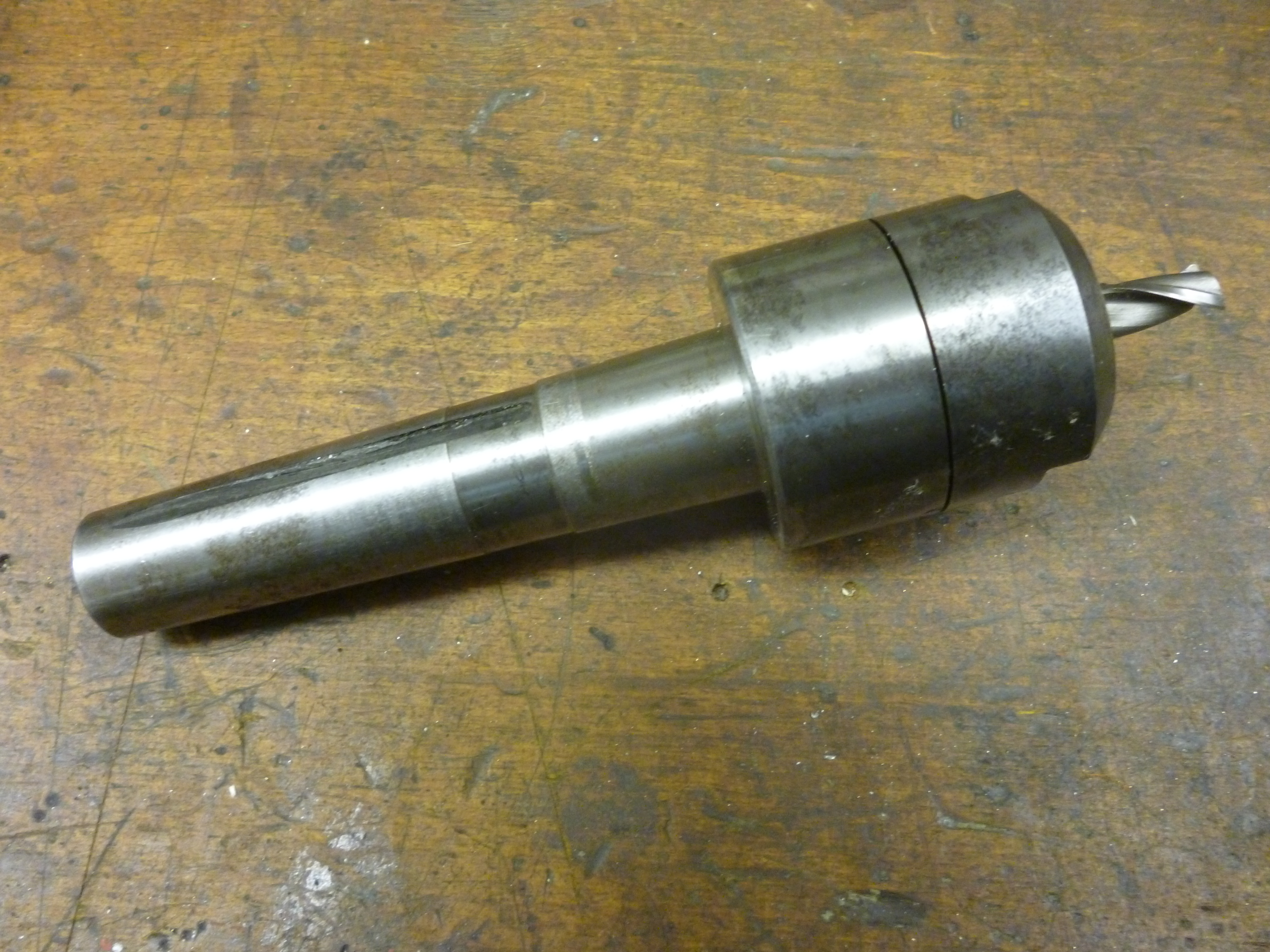
654 milling chuck with Morse taper
Fig male morse taper 654
The angle on a Morse taper is small enough for two Morse tapers to lock together. This feature is used on the headstock and tailstock on a lathe. These are both female tapers. The tooling that fits these will have a male taper.
One might have assumed that the angle on each size of Morse taper would be the same. But they are not. It is not even that they are different for some very subtle technical reasons. They all slightly different. When copying a Morse taper it is essential that the size of the taper being copied is the same size as that being made.
MEW no 26 p58 The Quest for Mr Morse
Another common taper is the International taper. This is often used on milling machines.

229 male international taper
The angle on this is such that it will never lock. This means when it is being used it always has to be held in using a draw bar.
Tapers on pins
Tapers are also used on pins. Pins like this are used to hold handles onto shafts. These pins are standard items and can be bought ready made. Regardless of the size, pins used the same angle of taper for the whole range. However, imperial pins have a taper of 1 in 48, i.e. 1/4inch in a foot. Metric tapers have a taper of 1 in 50.
External tapers like this can be made on the lathe. Internal ones cannot. They can be made by drilling with any ordinary twist drill and then reaming. They can also be made by using a special drill.
Of course the male and female tapers must be the same size to work properly. To be sure of getting this right is is necessary to be able to measure them. See
measuring small tapers
Measurement of tapers
Tapers can be measured in one of several ways.
One is if we look at the taper from above and split it down the middle. We can see this taper as a movement from the center line of so much per distance along. One way of expressing this is in so many inches per foot.
The first is in inches per foot
Half taper
Slope rise in mm/length in mm
Slope rise in inches/length in inches
Included angles
Half angles
Measurement I
Does it fit an existing taper?
Making tapers on the lathe
Tapers – height of tool
If a taper is to be as accurate as possible it is important that the height of the cutting point of the tool should be exactly at the center height of the lathe. This is not only because this will give the best finish, but because the angle of the taper being cut will be different, all else being equal, if the height of the tool varies from this.
See The Mathematics of Taper Turning, MEW no 22 p53
External Tapers
Whenever a taper is being produced it is always worth thinking about how the workpiece is going to be held before turning the taper. In general once a part has a taper on it, it cannot be held where the taper is. Often this means that for a given length of taper the workpiece will have to be longer than the final part so it can be held.
Usually shallow tapers have smaller angles than one might imagine. Do not try to guess an angle – measure it. With a very small angle, if the workpiece has a certain diameter one end and a certain diameter the other the distance between these two ends will vary dramatically with the angle of the taper
External Tapers can be turned in one of several ways. These are:
1 using the side of a cutting tool
2 turning the top slide
3 Offsetting the tailstock by moving the taikstock
4 simulating the effect of offsetting the tailstock by using an offsetting gadget
5 using a taper turning attachment
1 using the edge of a cutting tool.
In this method the angle of the taper is the angle of the edge of the cutting tool. This would usually be done with a piece of high speed steel ground to the required angle. The edge of the tool might only be a few mm long but many cuts in the same line will produce a long edge at an angle i.e. a taper. The cutting edge being used must be horizontal. There is no limitation on the angle of the taper.
This method will work however the workpiece is being held.
Chamfers
A chamfer is really just a very short taper. It is commonly used on what would otherwise be sharp edges. The advantage of this is that it makes handling the part feel nicer since the sharpness is gone. It also has the advantage that it reduces chances of the edge getting a ding. Even if it does it is of less consequence.
The angle for such a taper is often 45°. It is worth having a tool set up just for doing this as shown above. Notice it cuts a 45° chamfer that can be either left or right. for example a knob that has been knurled will usually be chamfered on both corners.
There are times when a 60° angle looks better. Since these chamfers are usually very short it is quite possible to have one cutter/ tool that will cut either left or right and either 45° or 60° chamfers.
fig two angle tool
When making a knob that needs to be chamfered both on sides from a piece of bar, knurl, chamfer the right end, start parting off on the left, when deep enough chamfer the left end, then finish parting off.
Knurls should always be chamfered at both end. See “Knurling” xxxx. This means that if a chamfer is put on the end of a round bar it will be necessary for the diametter of this bar to be less at the left hand end of the knurl to look right.
Longer tapers can be made using the cutting edge moved further along. On small lathes the length of cut is limited. It is far easier to do many short cuts rather than fewer longer cuts.

fig chamferl made with two cuts using the edge of the cutter
2 making tapers by turning the top slide
The top slide is normally set-up so its movement makes the cutting tool move parallel to the bed of the lathe. All top slides are made so that they can be rotated. If it is rotated the path the tool will take by moving the top slide will be at an angle to the workpiece and it will cut a taper. Almost any angle of taper can be cut like this. The maximum length of taper that can be is the length of the travel of the top slide. But it is perfectly possible to cut several tapers following the same line.
If the angle of the taper is not critical then it can be set simply by using the calibration on the topslide.
Using the topslide to copy existing tapers
method 1
Often the taper to be made has to fit an existing taper. In this case an existing taper can be used to set the angle of the top slide. Suppose we have a center fitted with a Morse taper. It has a female center one end and a male center the other. We can hold this by taking a piece of round rod and holding it in a three jaw chuck. We can drill a female center in it with a center drill held in a drill chuck in the tailstock.
We can now hold the center between the female center in the headstock end and a center in the tailstock.
L100 holding a center with a Morse taper
All of this assumes the axis of the center is parallel to the axis of the bed of the lathe. This can be tested by putting a center in the spindle and a center in the tailstock and supporting a test bar between them. Then use a DTI mounted on the saddle to test for parallelism.
The angle of the top slide can now be set. Fit a DTI to the topslide. Set the pointer to touch the side of the center. Make sure the probe of the DTI is touching the center along its center height. Rotate the topslide till the DTI gives the same reading along the whole length of the center as the topslide is moved.
Making a taper by turning the top slide – Method 2
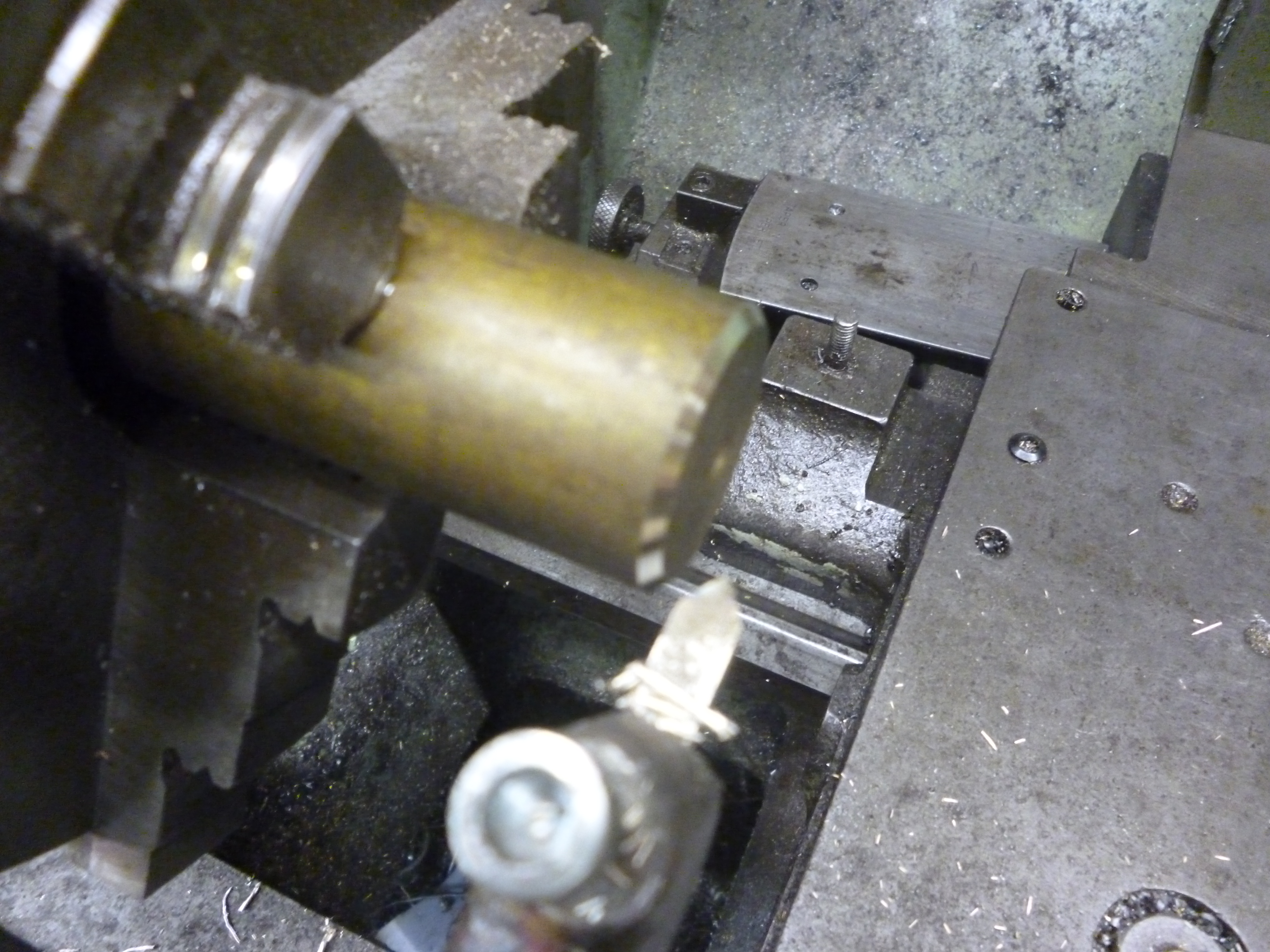
If we consider the above method we can derive a second method. What we need is for a flat surface touching the side of the center and another parallel flat surface touching the side of the top slide. But the height where the taper is and the side of the topslide are at different heights. The trick is to use a gadget as shown in the fig
Fig device for setting angle of the top slide
The round cutout is the fit the base of the topslide

Round part at the base of the topslide
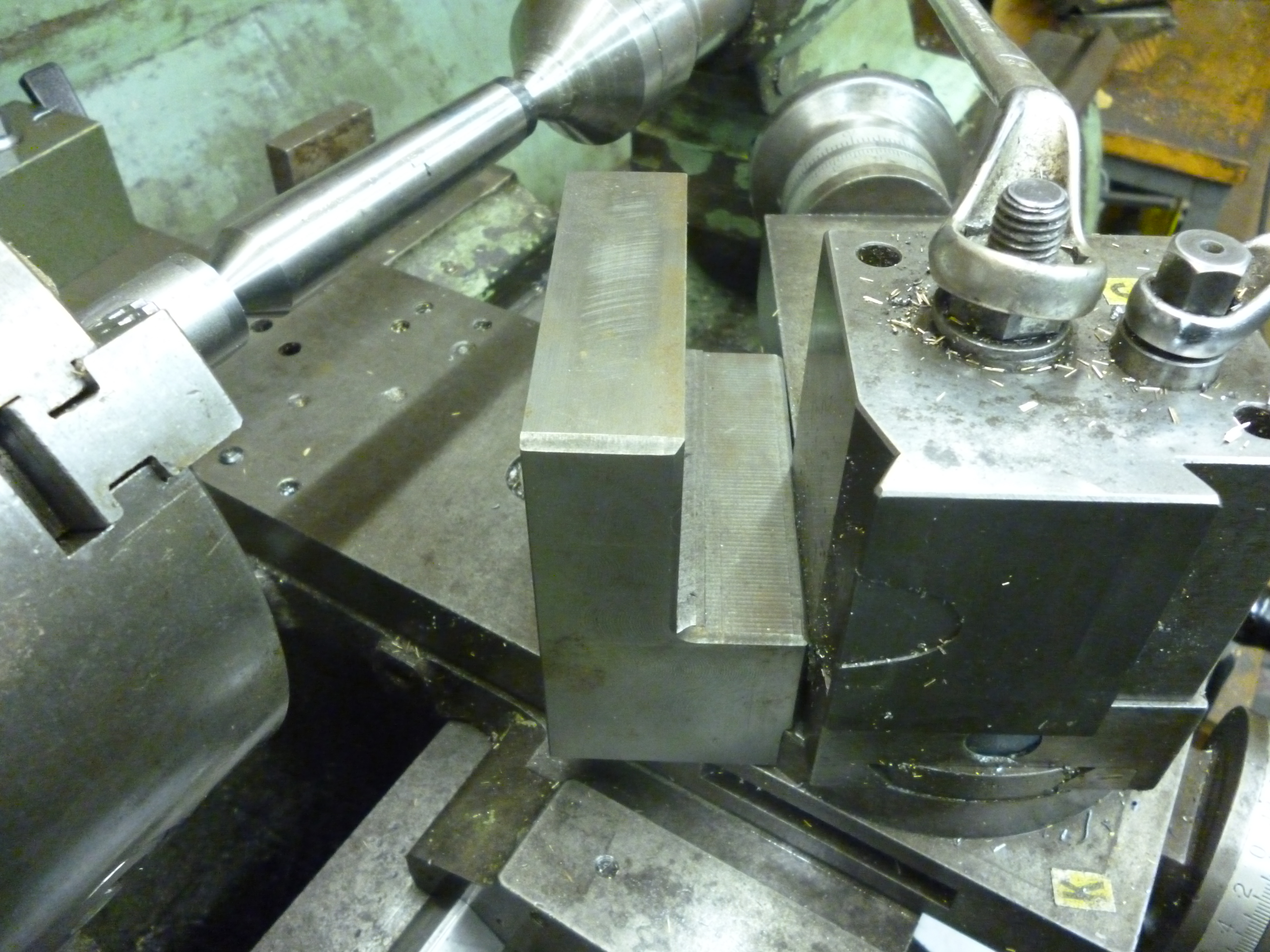
Tool fitted against the topslide
The top slide is rotated till one side of the device touches the taper and the other side touches the topslide.
Setting the angle of the topslide
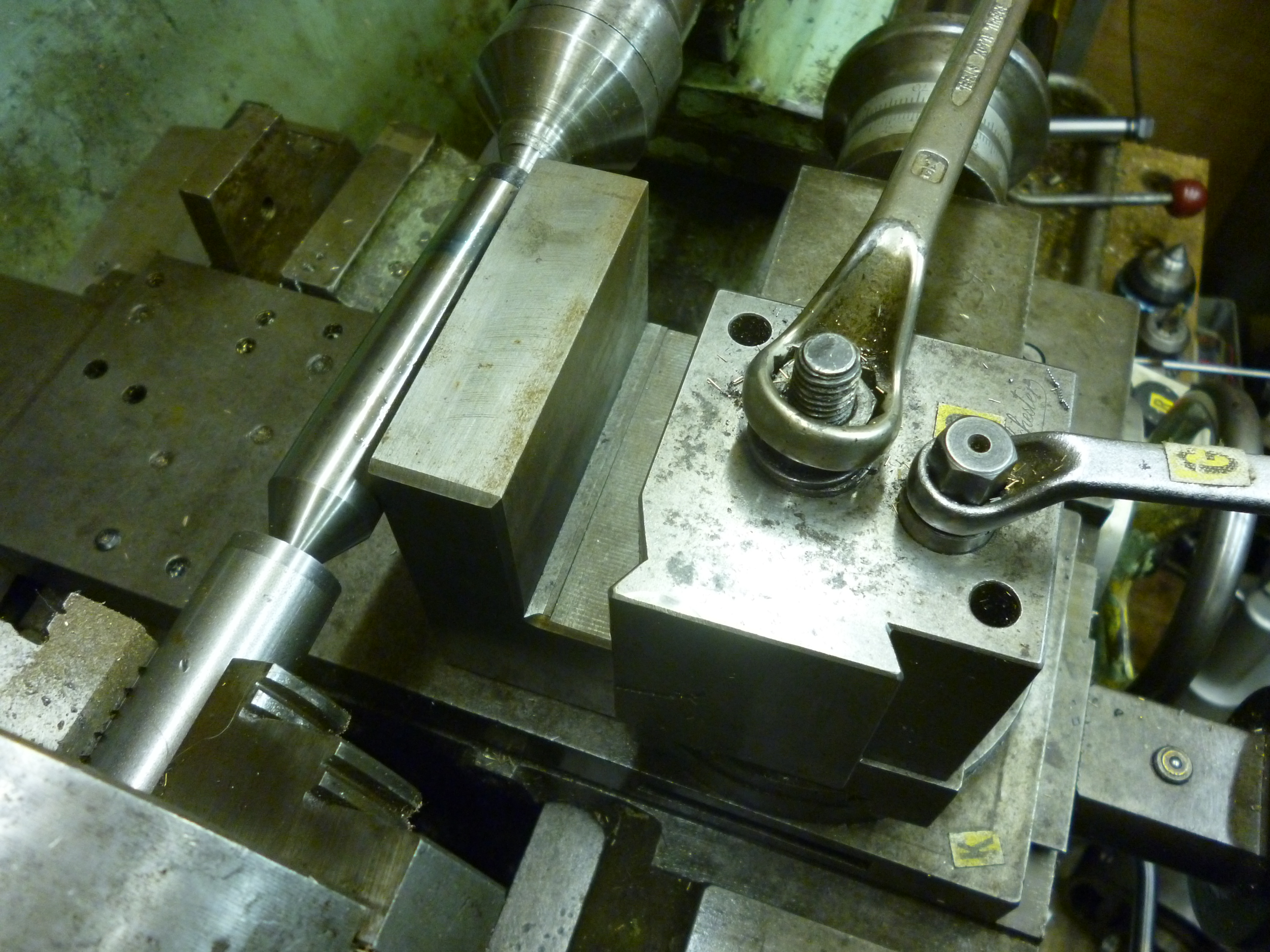
Making a taper by rotating the topslide – Method 3
This method uses a specially made tool. This tool clamps to the cross slide. It has a vertical part which has a small shelf fitted on it. The idea is that the base has two bars fitted to the underneath. One is used so that the vertical part is at right angles to the cross slide. The other bar is then used to clamp the tool firmly to the cross slide.
4204 taper turning attachment from below
Fig the underneath showing the two bars
The tool is fitted as described above. A sine bar is placed on the shelf. Its surface is at the same height as the body of the top slide. The angle can be set using slip gauges.

L108 gadget for setting the topslide
fig L108 setting the angle of the top slide
This method can be used to set the top slide for any angle precisely. But the maximum size of the angle is limited.
A five-inch sine bar is, by definition, exactly 127mm long
The offset for the following common tapers is (in mm)
Morse taper taper in/foot
0 0.62460
1 0.59858
2 0.59941
3 0.60235
4 0.62326
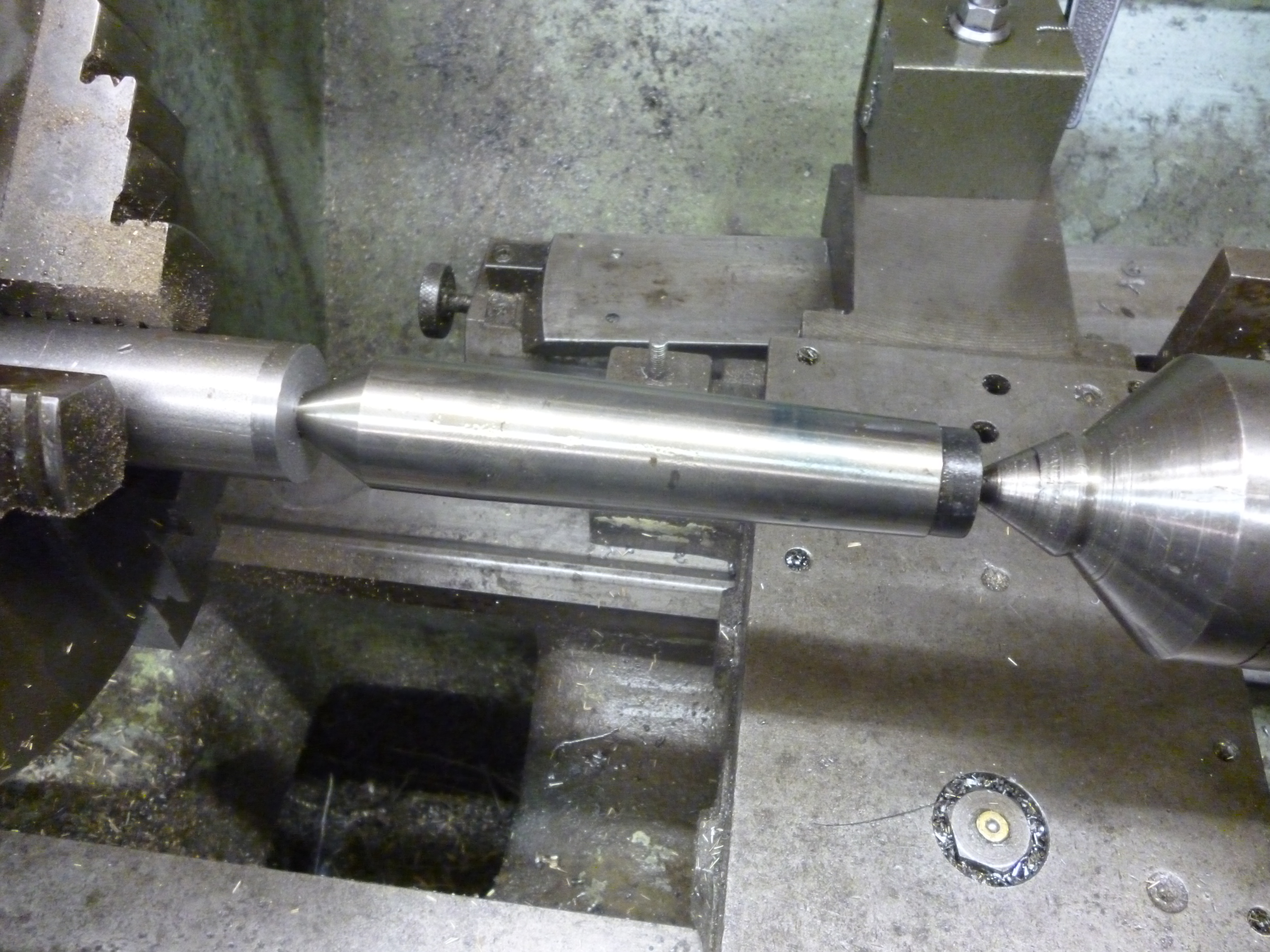
3 Making a taper by offsetting the tailstock – first method
When setting up a lathe one of the key alignments is to set the tailstock in line with the headstock. Any offset will mean that instead of parts with parallel sides being produce you will get tapered sides. This effect can be used to produce tapers. It has the benefits that no special equipment is needed and very long tapers can be produced.
The snags are more numerous. Only very shallow angles can be made. The workpiece has to be held between centers at both ends. These centers do not point at each other as they should and so compromise accuracy. This does not mean that the taper is not round. What is going wrong is that the taper in the workpiece is at an angle to the centers in both the headstock and the tailstock
fig showing problem
The workpiece is being driven round by a dog. If the workpiece touches the center at P1 when the workpiece rotates through 180º then that spot will now be at P2 and cannot be touching the center regardless of how the center has rotated. It would seem that the point touching the side of the center rotates round edge of the female center in the workpiece. Similarly the point where the tip of the center touches the workpiece also rotates round.
This could cause wear on the tip of the center which would cause the axis of rotation of the workpiece to move as well as reducing the effective length of the workpiece.
If the work piece is, say 12 inches long and the taper is 1 inch per foot the offset is 1/2 inch. The angle produced depends on the length of the workpiece for any particular offset. So if more than one piece is to be produced all the pieces have to be machined to the same length before starting on the tapers.

L107 Tailstock offset
fig tailstock offset L107
In the photo above the lathe was not designed to be able to make tapers by this method so the movement of the tailstock is limited. It is only there at all for aligning the tailstock with the headstock.
L109 making a taper by off setting the tailstock
Using this method will only work by holding the workpiece between centers. To do this as accurately as possible use a three jaw chuck to put centers in both ends of the workpiece. Offset the tailstock. Re-place the three jaw chuck with a catchplate and center. Fit a dog on the workpiece. Place the workpiece between the centers. Turn the taper. Use a precision protractor and a square to check that the angle of the surface of the workpiece is at the angle required for the taper.
(Turning and Boring, Machinery’s Mechanical Library No I p 80)
4 Offsetting gadget
One of the main problems with offsetting the tailstock is that it can be tiresome having to realign it afterwards. The tailstock-offsetting gadget offsets the workpiece without altering the setting of the tailstock. Instead of moving the tailstock this gadget fits in the tailstock instead of the center and has a center on it that can be offset. When it is finished with it is removed and the tailstock is just where it was before. Otherwise this method has all the costs and benefits of offsetting the tailstock.
Mew No 26 p12 tailstock taper turning attachment
The Tubal Cain’s method of doing this is to use a boring head in the tailstock. This is used by fitting it with a center instead of a cutting tool. This has the merit of being easily and accurately adjustable.
(ref mew no 56 p59)
see Tailstock Off Centre Tool – Peter Rawlinson – mew no108 p26
5 Making external tapers using a taper turning attachment
On a conventional cross-slide the slide moves because the distance between where the cross slide leadscrew is fixed, just behind the handle and the nut fixed to the slide varies as the handle is turned.
Most taper turning attachments are based on having a bar at the back of the lathe’s bed. This bar can be rotated to an angle to the lathe’s bed. The cross slide is attached to it so as the cross slide moves along the bed of the lathe it moves in (or out) so cutting a taper on the workpiece.
With a taper turning attachment, as the handle is turned it turns the leadscrew through a sliding joint. The fixed point of the leadscrew is held on a slide at the back of the lathe. This slide can be rotated so as the saddle moves the fixed point for the leadscrew moves in or out so as the tool moves along it the cross slide moves in or out and a taper is produced.
The rotating slide can only move through very small angles so only shallow tapers can be produced this way. However the length of a taper can be quite long 200-300mm. This is usually easily long enough for most of the tapers that are ever needed. But, if necessary, longer tapers can be made by repeating the same taper further along the workpiece.
The angle of the rotating slide is calibrated so it is quite easy to change the angle and make another, different taper on the same workpiece.
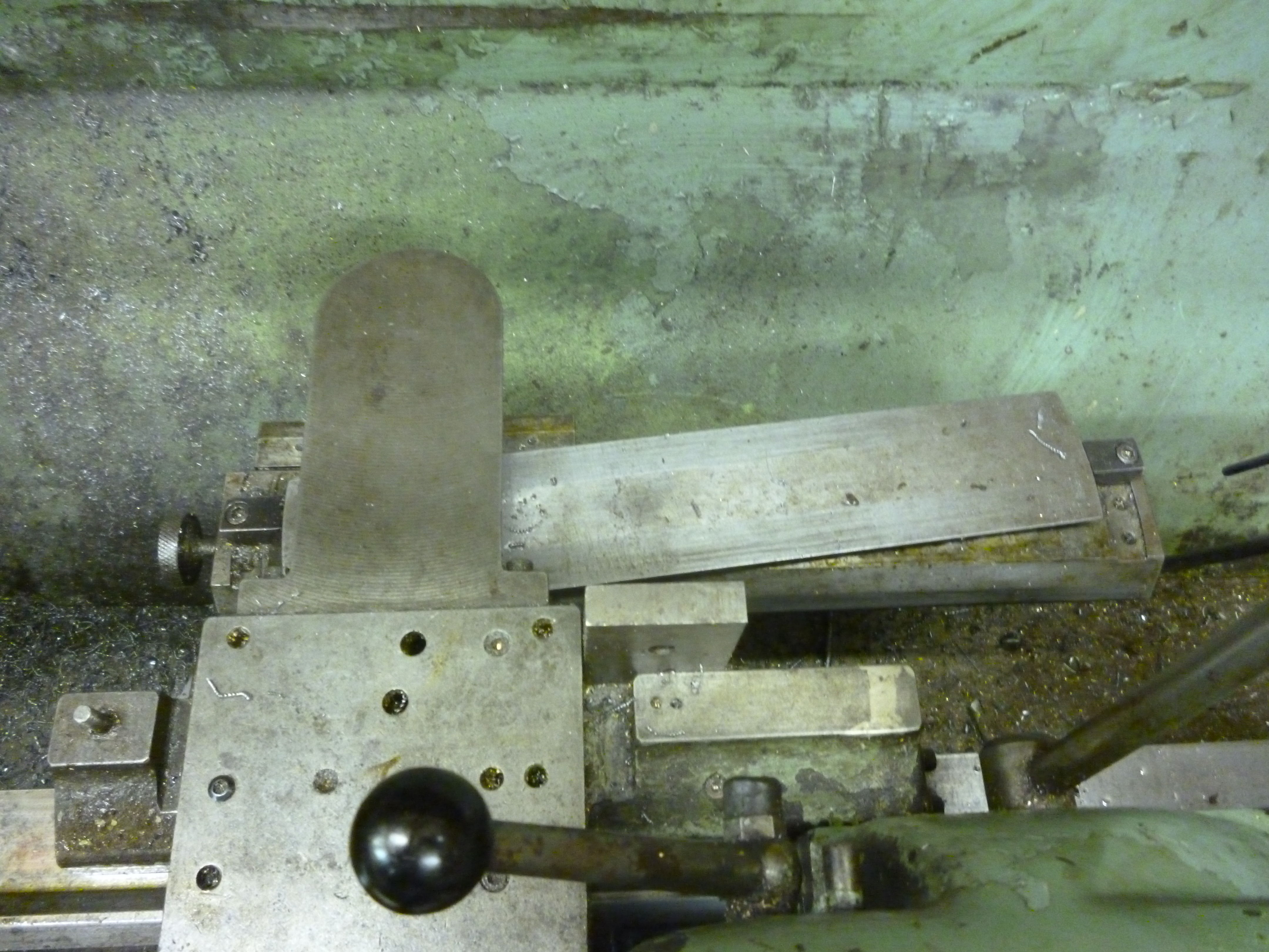
fig taper turning attachment from above
The taper bit is fixed to a part that is parallel to the bed of the lathe. Though not shown here there is a rod that fits this part on its right hand side at one end and fits a clamp projecting from the bed of the lathe at the right hand end of the lathe. This parallel part can be moved left or right to be anywhere along the bed of the lathe. This means that a taper can be made anywhere along the bed of the lathe though it is limited to the length of the swivelling part.

4202 taper turning attachment 2
fig taper turning attachment from the side
Fig – example of an axle with two tapers made using a taper turning attachment
On this sort of taper turning device it is essential that when it is not being used the coupling rod is completely disconnected. Even if it appears to slide freely when the screw is undone, it is possible, if the saddle is moved suddenly for it to stick though for just an instant. This of course, ruins the job.
When cutting a taper from right to left there is backlash in the system that means the saddle has to move quite a significant distance before the taper will start.

4203 the taper being turned showing parallel cut due to backlash
fig L109 parallel section before the start of the taper
There would be similar backlash if cutting from left to right.
With a taper turning attachment there is no limitation on how the workpiece is held.
A Taper Turning Attachment for Myford 7 series – mew no 9 p64
Mew no 25 p12 – myford taper turning attachment for 254
Method 6 Using the skiving tool
Mew no 27 p51 skiving tool
Tip for Bodgers
On an external taper all that is really required for it to “fit” is a tapered ring of metal at one end and another ring at the other end. If it is made like this and then it does not fit it is much easier to use some abrasive paper to get it to just fit.
Fig taper with just two ends
Multiple tapers
Where a surface has more than one taper on it and two tapers meet then careful thought is needed to ensure the tapers meet where it is needed. An example of this would be an axle where it tapers from both ends towards the middle. Very small errors can lead to the tapers not meeting quite in the middle.
External tapers – a special case
Very long male reamers are often used to ream out holes when making various members of the woodwind family of musical instruments. These can be very long and yet quite thin. Sometimes the angle of the taper is not uniform over the whole length of the taper. Since they are to be turned into reamers they often need to be made of something like silver steel that can be hardened.
An example of this is the bore for an oboe. On most woodwind instruments the bore is cylindrical. On the oboe it is conical. A common oboe is about 600mm long. But it is made in three sections not more than 220mm long. This means three reamers are needed.
1 If the workpiece is supported between centers, is thin and gets hot there is a serious risk of it buckling.
A travelling steady can be used if the workpiece is round, parallel and concentric with the spindle at the start of the job. Work is started at the right hand end, short section of the taper is done to completion. The saddle is then moved left and another section is done and so on.
2 A variation on 1.
The workpiece is inside the spindle and only a short length, say, 50mm, is outside the chuck. This does mean that the workpiece has to fit inside the spindle. This is turned to the final taper required for this section. The workpiece is brought out by another 50mm and this section is turned to completion and so on till the job is finished. See and MEW no 54 p63
For reamers for musical instruments see MEW no 53 p63
Taper pins
Round parts, such as a handle, are often fixed to a shaft using tapered pins. Imperial taper pins have a taper of 1 in 48, that is, a quarter of an inch per foot. Metric taper pins have a taper of one in fifty.
This taper is even less than that of a Morse taper. This is because with this taper the male pin will fit very tightly in the female taper. It needs to be hammered in but it also needs a hammer to get it out.
Male tapers like this are usually short and can easily be made by turning the topslide. The female taper can be made by drilling a hole and then using a special reamer designed for doing this.
fig tapered reamer for reaming holes for tapered pins
Such pins would normally be hardened.
Turning tapered threads
When it is necessary to make a tapered thread it is only possible if the feed from the chuck, through the gear box and to the leadscrew is driving the saddle at the right speed. This means a tapered thread can only be cut using the feed for screw cutting. One covered that this can be done with is the tail offset method. however because the workpiece is driven by a dog this might not be perfect but this is unlikely to matter. The indisputably best way would be with a taper turning attachment.
Steadies when machining tapers
Very thin tapers can be supported by means of a steady.For example if it is necessary to drill the end of a thin taper, for example, a stanchion, a stead can be made by drilling a hole in a thin piece of steel that be held in a quickchange toolholder. This hole can be moved along the taper till the taper just fits the hole. It can then adjusted in the x direction using the cross slide and in the y direction by the height adjustment that already exists in a quick change toolholder.
Tapers – internal
Internal tapers are significantly different from external tapers in that they can only be supported at one end – there is no metal to put a center in.
The whole point of any taper is that its axis is coincident with the axis of the outside of the workpiece. Where the workpiece is only supported at the chuck end causes a problem. The solution is the use of a fixed steady to hold the workpiece at the right hand end.
If the workpiece is short it can be held in a chuck.
It is impractical to use the edge of a cutter as a form tool. It is impossible to use the tail offset method since this relies on having a center in both ends of the workpiece.This leaves us two methods. It can made by turning the topslide or by using a taper turning attachment. Whatever method is used the tool will be a boring bar.
One advantage of making a female taper compared to making a male one is that the taper can be finished by using a tapered reamer.
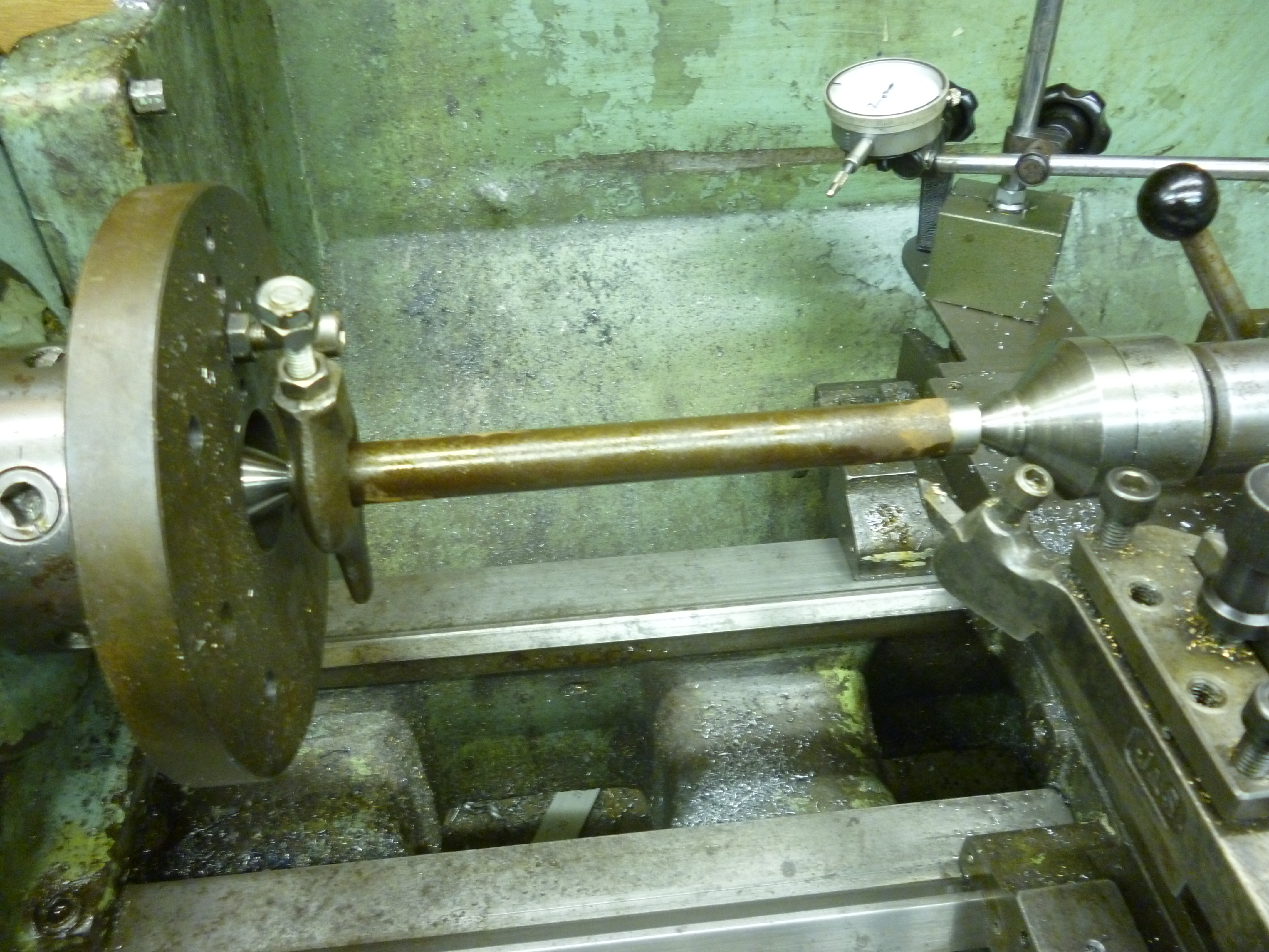
Special case – very long workpiece
Far more interesting is the case where the workpiece is long. This is very important because this is the basis on most spindles as so often used on machine tools. The example that is most frequently met by the model engineer is a spindle for a tool and cutter grinder.
Centers are cut in each of the workpiece.
The outside of the spindle is turned between centers, one in the headstock spindle and the other in the tailstock.
This part is then used to setup the fixed steady. The fixed steady is fitted to the bed of the lathe loosely. The spindle is then put back between the centers. The position, longitudinally, of the workpiece held like this will not be the same as when it is held in the chuck later. The steady is clamped to the bed of the lathe at the point on the workpiece where it will be when turning vthe taper. The arms of the fixed steady are adjusted so they just touch the workpiece. They are locked in this position. This is not easy to do. I will come back to this later. The fixed steady is now set up but is not necessarily in the right place along the bed of the lathe. The steady can be moved right along the bed so it is out of the way for the moment.
The center in the headstock is removed and a four jaw chuck is fitted.
One end of the workpiece is then held in the chuck. It cannot be held with a center because this would only work if there was another center at the other end. The chuck is adjusted till the workpiece is concentric at the chuck end. This has to be as concentric as possible. This should be done with a dti that measures to a thousandth (of a mm). However Prof Chaddock in his “Quorn Tool and Cutter Grinder” book uses a three-jaw chuck. He does this by using the Grip-Tru emulation.
Of course if everything was perfect the far end of the workpiece should still be concentric. But most people will find a small error. The steady is fitted on the workpiece at the required spot and clamped in place.
It will be noticed that though all tapers have a narrow end they never end in a point. The narrow end has a width. In the case of female sockets it is always possible to drill out the socket using a drill of the width of the narrow end of the taper. This best done by drilling with a smaller drill, say, 5mm, followed by the final drill. The small drill might need to be a long series one.
A boring bar is fitted to the topslide.
The taper can now be cut either by turning the top slide but, unless the taper is short it will have to be done a bit at a time.
A far better method is to use a taper turning attachment. It would be a bit optimistic to think this will work on the first try. the problem is the way the back lash on the taper turning attachment works. Do a dummy run to check.
On any taper it is not only the angle that matters but also the width at either end. Male tapers are designed to go a very specific distance into the female taper. This can be tested by trying to fit a male taper into the female one being cut from time to time.
Turning the spindle in its own bearings
One limit on the accuracy possible is the tightness of the arms on the fixed steady. Most spindles will be fitted with bearings when they are finally fitted to the system they are part of. If a bearing that will be used is fitted to the spindle after the outside of it has been turned then this can be used for holding the spindle when the taper is being bored. In this case the arms of the fixed steady can be pushed against the bearing as firmly as possible.
fig spindle being turned in its own bearing
This will only work, without complications, if the bearing is not a tapered roller bearing.
references
The Mathematics of taper turning, (no author given credit), MEW no 22, p53
A Tailstock Taper Turning Attachment, Dennis Major, MEW no26, p12
Self holding Taper Sockets, Alan Jeeves, MEW no 26, p23
Making concentric Morse taper spindles, David Dew, MEW No 30, p26
Making your own Morse tapers, Gordon Read, MEW no 34, p24
A Beginners guide to the Lathe – part 11 – tapers, Harold Hall, MEW no 46, p40
Machine Tapers – Philip Amos, MEW no 56, p 56
Taper Turning by Offset Tailstock Centre, Doug Ball, MEW no 71, p35
Lathe Projects for Beginners – part 9 – precision tapers, Harold Hall, MEW no 75, p29
Two heads better than one – Will Bells, MEW 106 p12 (turning tapers)

Great write up and details.I have been trying to turn an M3 taper for my hercus AR for running spindle chucked milling cutters and such but finding it difficult to get a perfect fit, it is either locating at the rear and when I try to rectify it it go’s the opposite to the front or in the centre.I find that just the minute movement of the compound slide has dramatic effects. i even tried filing to get it to fit but no luck as yet. I will give it another go tomorrow with hopefully a new approach at the setup useing the m3 centre I have as a gauge and using a peice of square steel between the centre and the comp slide. I am finding this very intreaging as things are not what they seem to be in this situation,a b—— good leaning curve,not that I realy need it at 88yso but I wont let it beat me. I have a pretty good engineering background but have not come accross this situation before as most of the tapered gear is purchased but I thought I would give it go just for a bit of fun,OH BOYit sure aint much fun.
Cheers robhc78
I don’t know if this is on my websites but the general solution to making correct tapers is not to attempt to make. Insteaed use a standard taper in the form of a tapered sleeve.
Make a nearly right taper on the end of the bar that is the workpiece and then araldite a sleeve onto the stub. So if you want a 3mt use a 2-3 taper sleeve and turn up a taper close to 2mt. Cant fail.
john f