Making tapered flutes on a conical surface
Usually flutes are made on flat or round surfaces. This means the flute is the same width from one end to the other. But a flute on a cone has to taper to look correct. The traditional flute goes back to the flutes carved on stone pillars. For practical reasons flutes often have a land between them. Also for practical reasons the inside corner of the flute is rounded. A wide flute may have a flat bottom but the corners are rounded. If the flute is narrow then the shape might be just hemi-circular or even a shallow arc.

30b flutes on conical surface 3
The workpiece is made of the required conical shape on the lathe.

turned workpiece for flutes on a conical surface
for the flutes to be the same depth from one end to the other means that the cone has to have the surface where it is being cut horizontal. It also has to be possible to rotate the cone about its axis. This can be done with a tilted dividing head.
This requires the dividing head to be tilted. But most dividing heads that can tilt are usually too big in that by the time they are mounted on the rotary table and then tilted the space between the workpiece and the cutter will have disappeared. The way round this is to use a plain dividing head, ie, one that cannot tilt, and mount it using a wedge.
But because it is a cone the flutes have to be wider at the bottom end of the cone than at the top end. It also has to rotate, slightly about an axis perpendicular to the flute. This can be done by mounting the dividing head on a rotary table.
Most rotary tables that will fit the milling machine will not be big enough to hold the dividing head in the required position. But, in this case, the rotary table can be extended since it only needs to be long along the x-direction of the milling table.
The rotary table is aligned with the axis of the spindle and then locked in the y direction.
the dividing head is aligned on the rotary table so that its axis intersects the axis of the rotary table. The point of intersection is the top end of a flute. Once this has been done the dividing head does not move relative to the rotary table.
The aim is that at the top end of the flute, the width of the flute is the width of the ball ended slot drill – about 3mm. At the bottom end it is such that the land between the flutes is parallel along the length of the flute. The flute is tapered by about 1 degree on either side.
For each flute the table is rotated one way, milled, rotate a small amount, and milled. This is done till all of one flute has been milled. The workpiece is then rotated to do the next flute. This means the sequence is x degrees spacing for each milling run y times then rotate by z, the spacing from one side of one flute to the start of the next flute. It is worth printing this out using a spreadsheet and ticking each line as it is done.
In all of these cases the flute can be cut with a ball ended cutter.
- 470 tilted dividing head on rotary table
 dividing head on a wedge on a rotary table 470
30 tapered flutes on conical surface
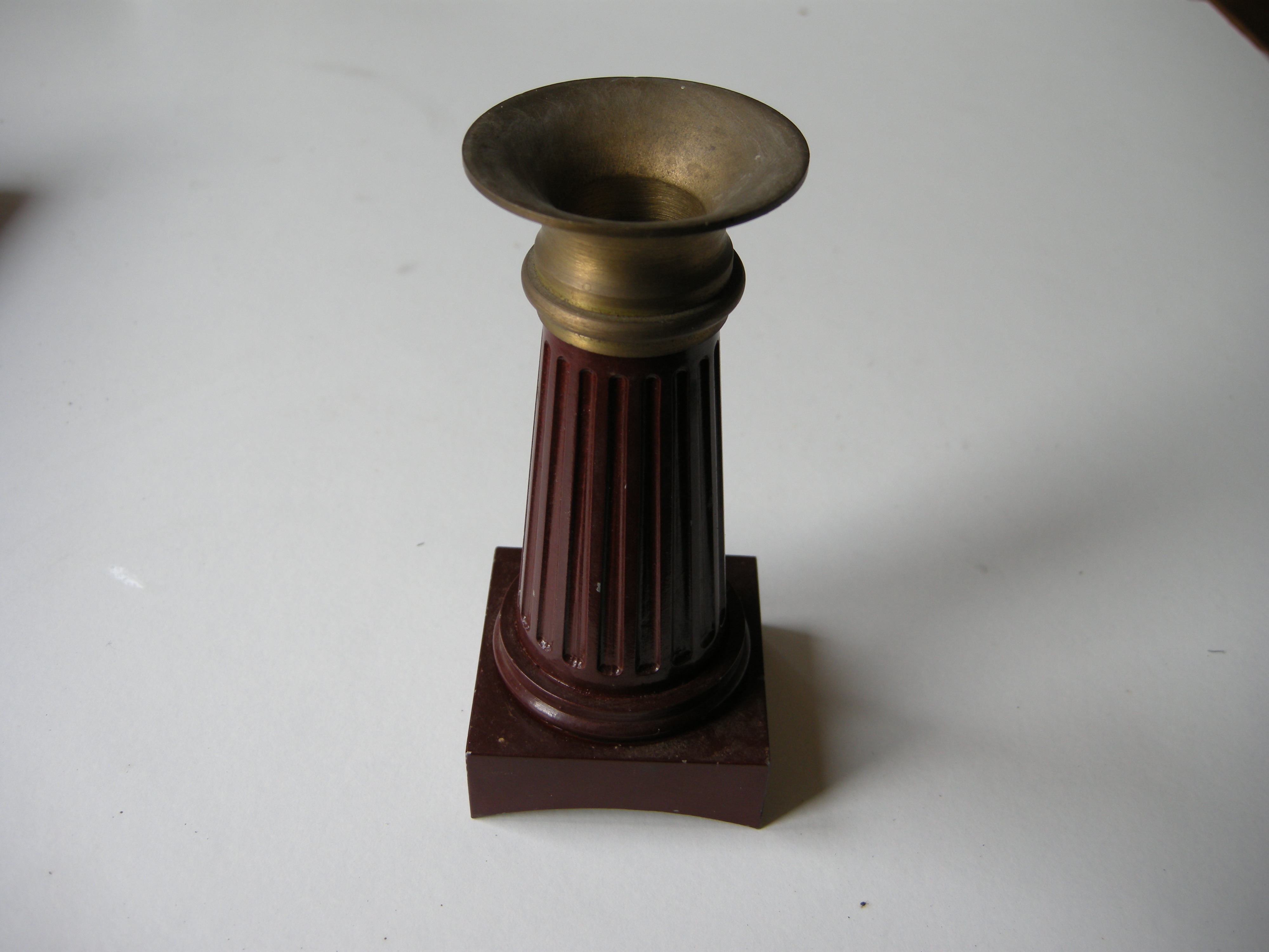
Fig. Safety valve cover with tapered flutes 30
Alternative method
If the milling machine happens to have a swivelling table then this can be used instead of mounting the dividing head on a rotary table.

using a dividing head on a milling machine with a swivelling table
For this to work the top of the flute must be positioned exactly above the point where the milling machines table swivels.In this case the dividing head has had to be fitted right at the very end of the milling table.

John, that is a very nice and clear description of what is a complicated sequence.
In order to obtain the tapering of the width of the flute, would it work if the depth of the flute was progressively reduced, to progressively use less of the width of a semicircular cutter? Or would that look wrong? John (of johnsmachines)
sorry i seem to have miss this. The whole point of this method is so the depth of the flute is constant. This is not to say all flutes are of a constant depth but this was only to achieve the appearance that they were.
john f
Hi John, I am still quite new to turning and model engineering generally. This technique sounds quite daunting for me. Could I cut my flutes straight to equal depth and width along a 5” column with a 3 mm ball end mill and the run a 3.5mm ball end from one end getting progressively shallower along the flute?
Mmmm, I dont think so. If you look at the flutes on any classical column you will notice the depth of the flute
is constant along the length of the flute. Of course a tapered flute would not be found on a Greek or roman
column but from our experience of seeing flutes I dont think one that varied depth would look right.
john
John, thank you for your reply. I agree completely, but my thought was to set the final depth with the first mill and use the slightly wider mill to decrease the width of the flute by withdrawing it from the flute as it moves along the length of the flute, thereby tapering the sides but not altering the depth of the flute. I will have to experiment and will let you know.