go to the home page
go to the page above this one “helical gears – links”
Making helical gears on a vertical milling machine.
It is pointed out elsewhere that most amateurs will not have a suitable horizontal milling machine for making helical gears. However it is just as easy to make helical gears on a vertical milling machine. The main and probably only drawback is that the setup for helical milling on a vertical machine is not as rigid as it would be on a horizontal machine.
The trick here is that the gear cutter is held on a stub arbor held in the vertical socket. But the vertical head is tilted. This tilt sets the required helix angle.
Cutting a helical gear is just like cutting a spur gear except for some key differences:
A whilst the gear is being cut, the milling table moves by rotating the leadscrew to the table. The rotation of the leadscrew is also used to rotate the dividing head,
B the cutter has to be at the helix angle to the axis of the part whose surface is being cut
C The cutter is the same sort as used for cutting spur gears, but which one of the set is needed is affected by the helix angle.
The cutter
The cutter is a standard Brown and Sharp cutter.
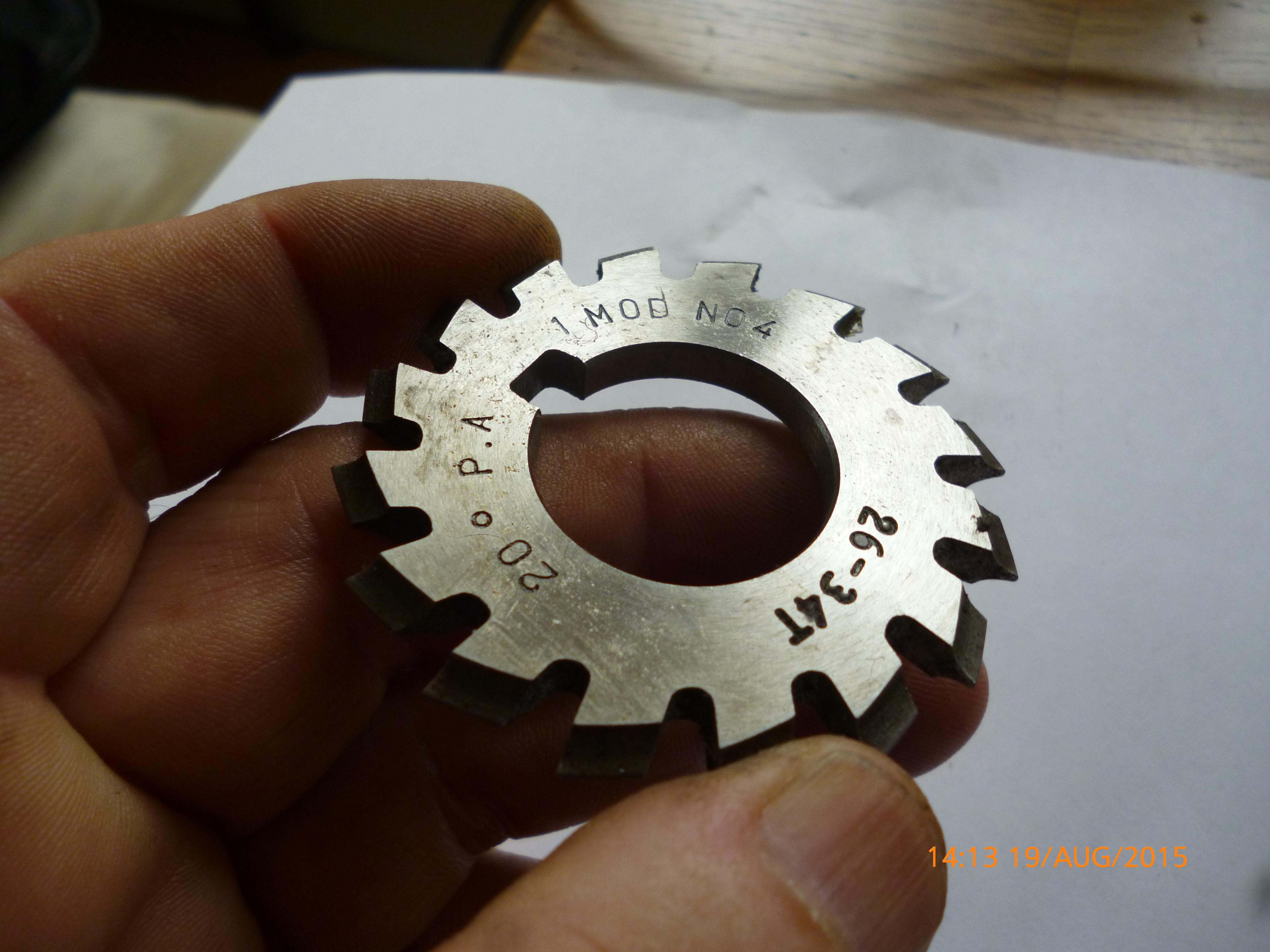
fig 2450 Brown and Sharp type cutter – first side
This has been chosen for this example. It is for making 1 mod teeth with a pressure angle of 20º. It makes a gear with 26-34 teeth.
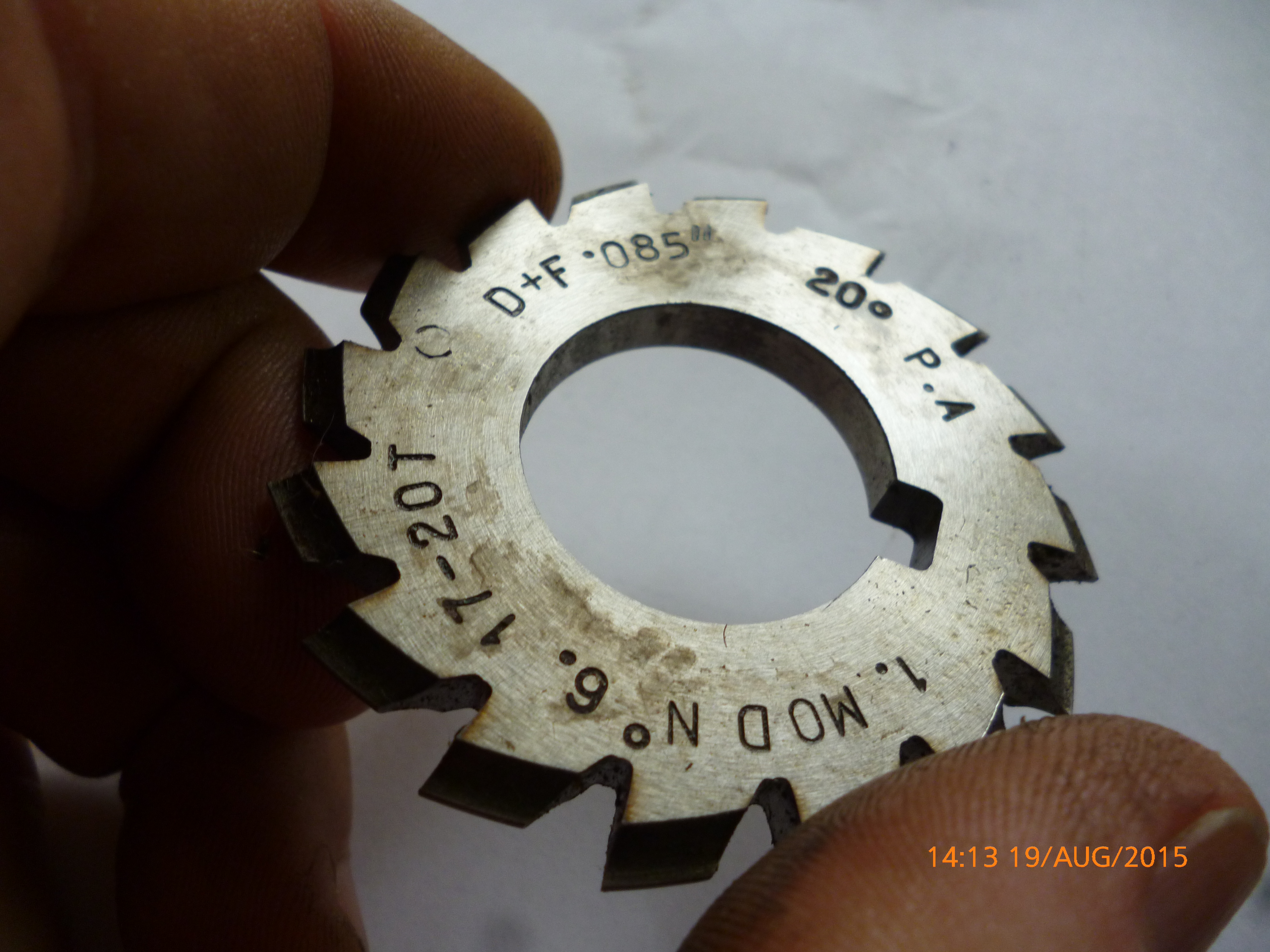
fig 2451
This is one side of another cutter in the set. It is shown because it is the only one marked with “D + f 0.085” . This is the depth of cut which is “D” and “f” which is the clearance.
The choice of cutter
For a helical gear with N teeth the cutter that has to be used is the one that would have been used for a spur gear with N’ teeth where:
N’ = N / cos ^3 * (helix angle)
For example, suppose the gear is to have 30 teeth and the helix angle is 17º 45″ then the cube of the cosine of the helix angle is 0.9551 the cutter required is the one for N’ teeth.
N / 0.8712 cubed = 30/0.8712 = 34.43
The cutter for a spur gear with 34 teeth is no 4. In this case it happens to be the same
This rather unexpected result is proven in pages 25-28 in “Spiral and Worm Gearing”
It will be noticed that the cutter needed is always for a larger number of teeth than the number needed. Normally, with spur gears, the smallest number of teeth that can be cut is twelve with cutter no 1. This means it is possible to cut helical gears with fewer teeth than this.
The cutter is fitted onto a stub arbor. The stub arbor is fitted into the vertical socket. The vertical head is tilted to the required helix angle.
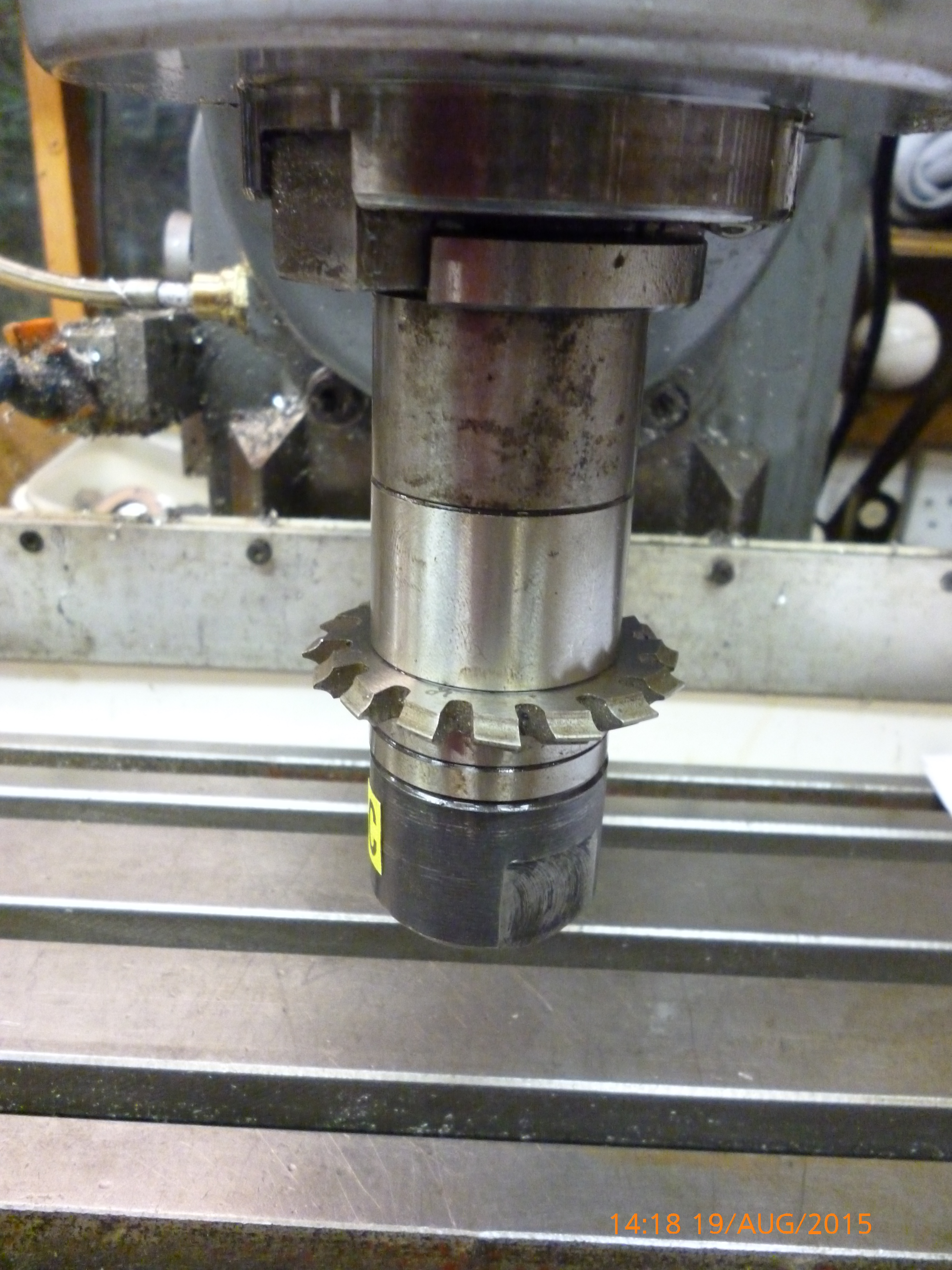
fig cutter on stub arbor fitted to vertical head (2452)
Different ways of tilting the vertical head
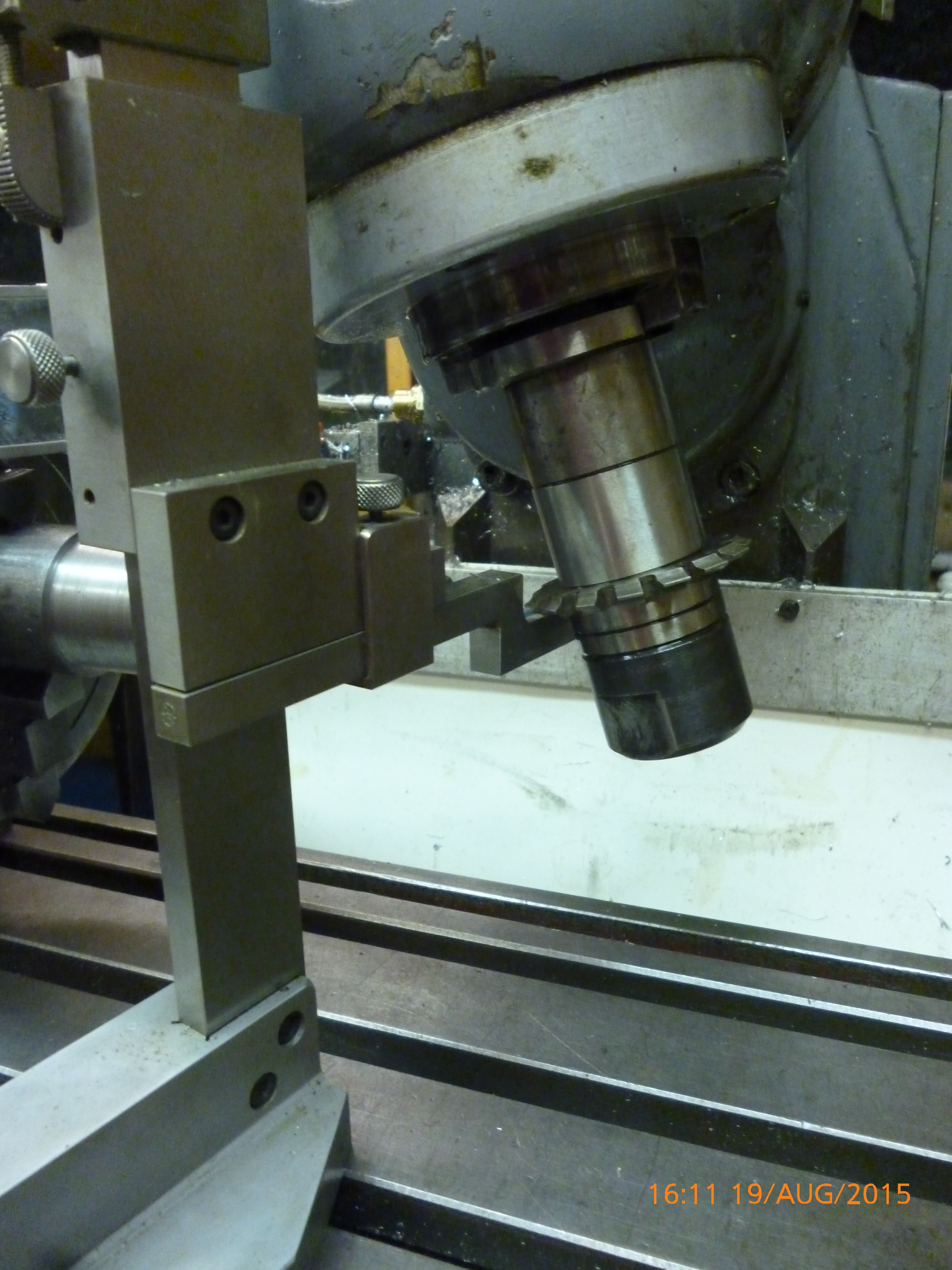
The vertical head is tilted at the angle of the helix angle. However the head could be in front or behind the workpiece and it could be titled to the left or the right. Furthermore the cutter could rotate clockwise or anti clockwise.
In the photo above the cutter has been fitted so it will only cut if it is rotating anti–clockwise (looking from above). In this case the workpiece would have to move right to left if it was in front of the cutter or it would have to move left to right if it was behind the cutter.
Height of the milling table
It is essential that the center height of the workpiece is at the center height of the cutter, which happens to be tilted. One way of working this out is as follows. With the table at any convenient height measure the height of the top of the cutter.

2455 helical milling 6
fig 2455 measuring the heught of the top of the cutter
Then measure the height of the bottom of the cutter. On this height gauge it is known that measuring using the top side of the bar needs an allowance of 10.86mm.
The height of the bottom of the cutter is measured.
2456 measuring the height of the bottom side of the cutter
The difference between the top height and the bottom divided by two is the height of the top above the center height of the dividing head. This happens to be 110.00mm. It is now possible to raise the milling table so the height of the top of the cutter is half the height of cutter plus 110.00mm
The milling table is raised or lowered till the center height of the dividing head head is at the height of the middle of the cutter.
The workpiece
The workpiece can be held using a mandrel, an arbor or between centers. This is described in
“Dividing head – holding the workpiece“.
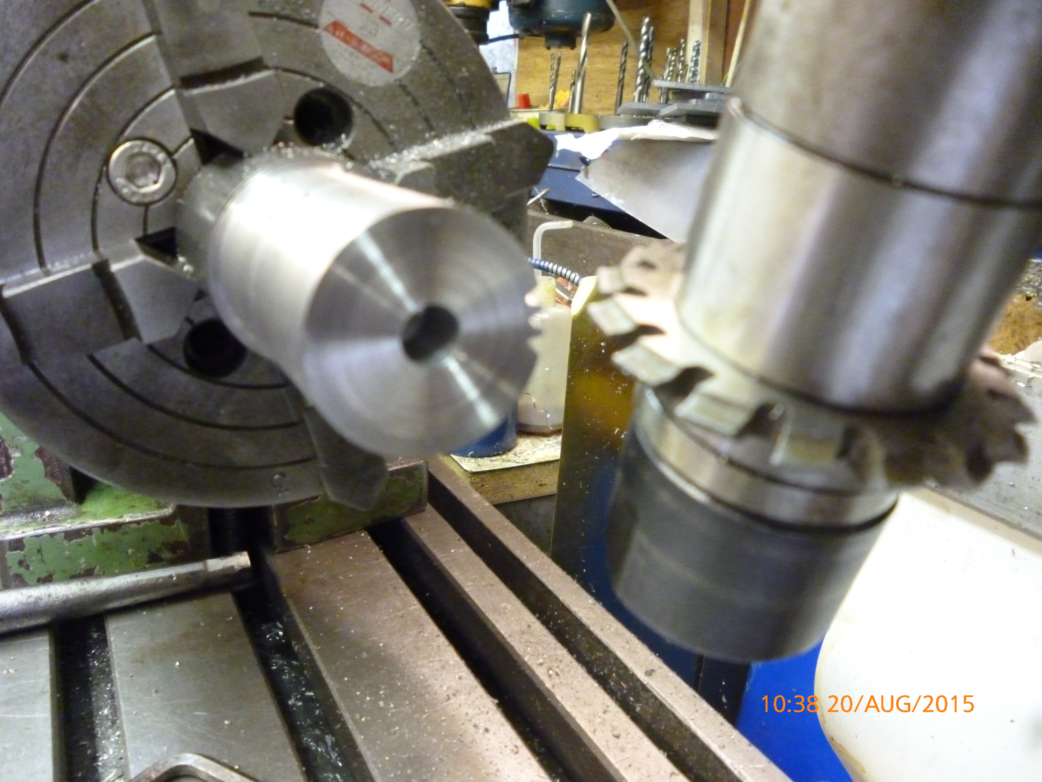
The whole point of all of these method is to make sure the workpiece is held concentrically. But another way is to make the workpiece from a round bar which is turned in the lathe and then held in a four jaw chuck on the dividing head.
The first step is to turn the workpiece down to the outside diameter of the gear we want to make. We can avoid any complicated maths by simply looking up the gear we want to make in a catalogue. For example:
Suppose the gear is to run with its axis parallel to another similar gear. It is to have 30 teeth. the pressure angle is to be 20º The size of the teeth is 1 mod.
The catalogue has one with a helix angle of 17 deg 45 minutes.
The pcd is 31.5mm.
The od is 33.5mm.
This is the outside diameter of the workpiece. This would usually be turned on the lathe.
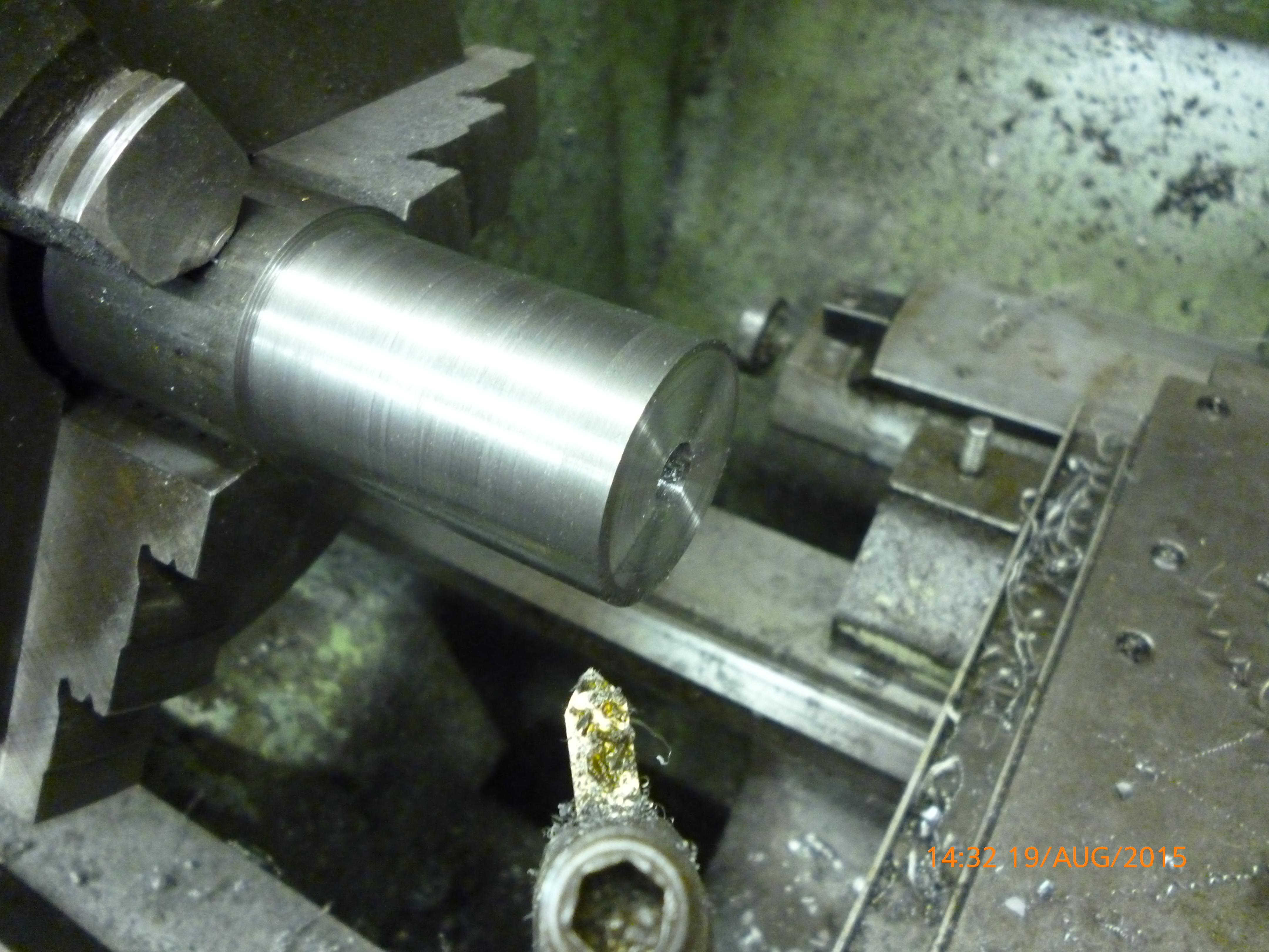
fig preparing the workpiece.
It is essential to center drill, drill and ream the bore of the gear at this stage.
Notice that the workpiece is not perfectly centered in the chuck. This does not matter here because when it is being machined on the milling machine it will be held in a four jaw chuck and will then be centered accurately.
Setting up the dividing head
The dividing head is mounted on the milling table so that its axis is parallel to the milling table both horizontally and vertically.
If the tailstock is being used it must be fitted so the workpiece etc is also parallel both horizontally and vertically.
If an arbor is being used or the workpiece is just a piece of round bar then the workpiece must be centered in the four jaw chuck on the dividing head.
The dividing head is set up to divide the circle for the number of teeth needed on the gear being made. How to do this is covered under,
“Dividing head – dividing the circle”.
The whole process is started with the pin on the dividing head in hole zero of whichever ring of holes is being used..
The workpiece is fitted in the four jaw chuck on the dividing head. It has to be centered as accurately as possible. Any error here say, 0.1mm will mean that teeth on one side will be 0.1mm too big and on the other side will be 0.1mm too small. For very small teeth this can make the gear produced useless.
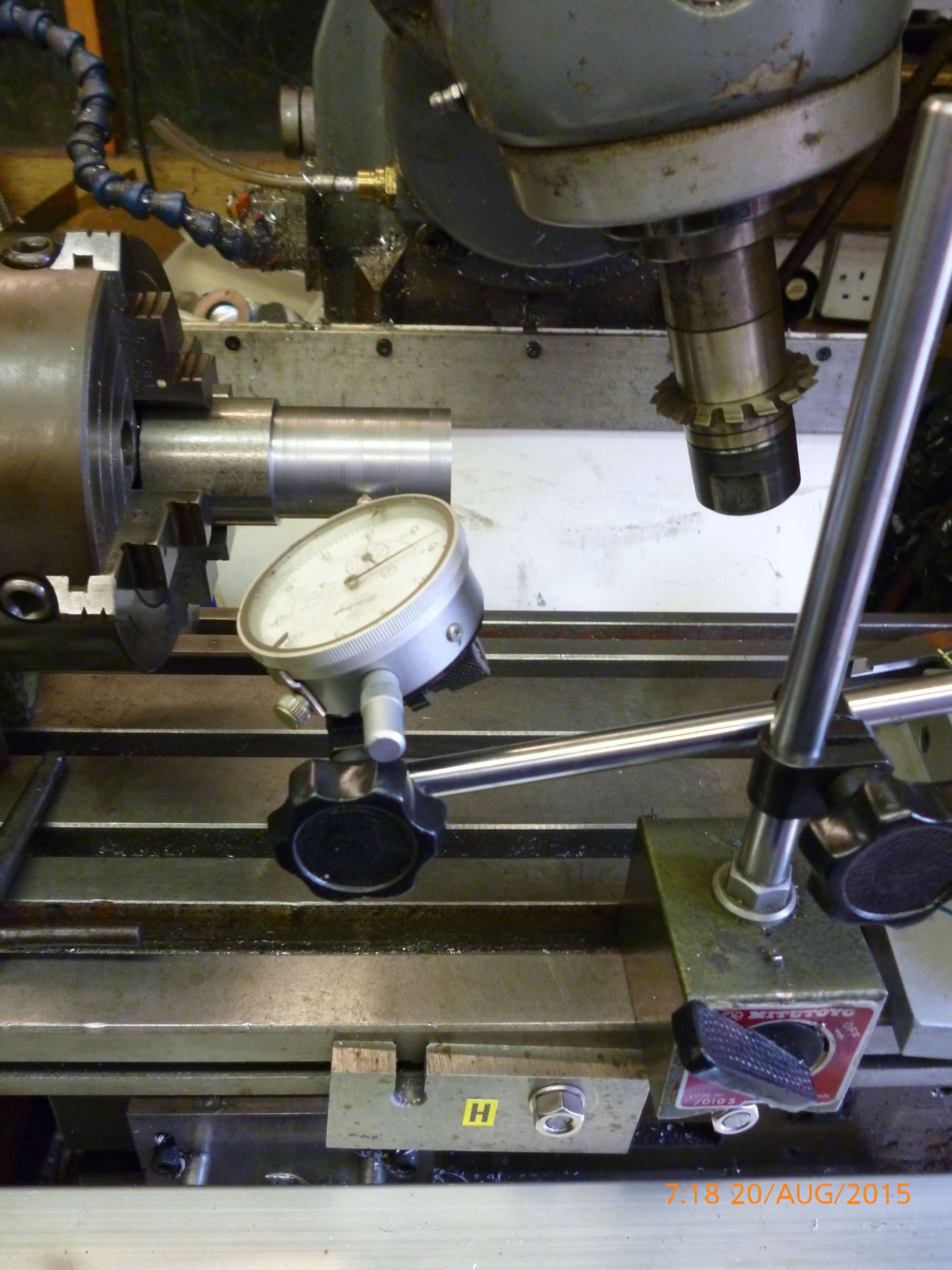
2469 centering when cutting helical gear
The gear train
The leadscrew is connected to the auxiliary input on the dividing head by means of a gear train. The leadscrew can either be driven by a motor or by hand. The ratio required is that needed to produce the lead required. The lead is determined by the helix angle and the pitch circle diameter of the gear being made..
To find the lead for the tooth’s helix angle multiply the pitch circle diameter by pi divided by tan(helix angle).
lead = PCD * pi / tan(helix angle)
lead = 31.5 * 3.142 / 0.3201
= 309.2mm
This means that for one complete turn of the workpiece the milling table must move by 309.2mm.
For one complete turn of the workpiece the auxiliary input must turn 40 times.
On the milling machine being used the pitch of the leadscrew is 5mm, ie, one turn of the leadscrew moves the table by 5mm.
The number of turns of the leadscrew required to give required movement is:
distance needed/pitch of leadscrew 309.2/5
this has got to produce 40 turns at the auxiliary input. The difference is made up by the gear train
(309.2/5)/40 = R
R = 1.546
Using Hobnail the gear train suggested (using a very limited set of gears) was:
100, 86, 64, 48
Roughly, it is 60 turns of the lead screw to produce 40 turns of the auxiliary input so the leadscrew is fitted with the 48 toothed gear and the 100 toothed is fitted to the auxiliary input.
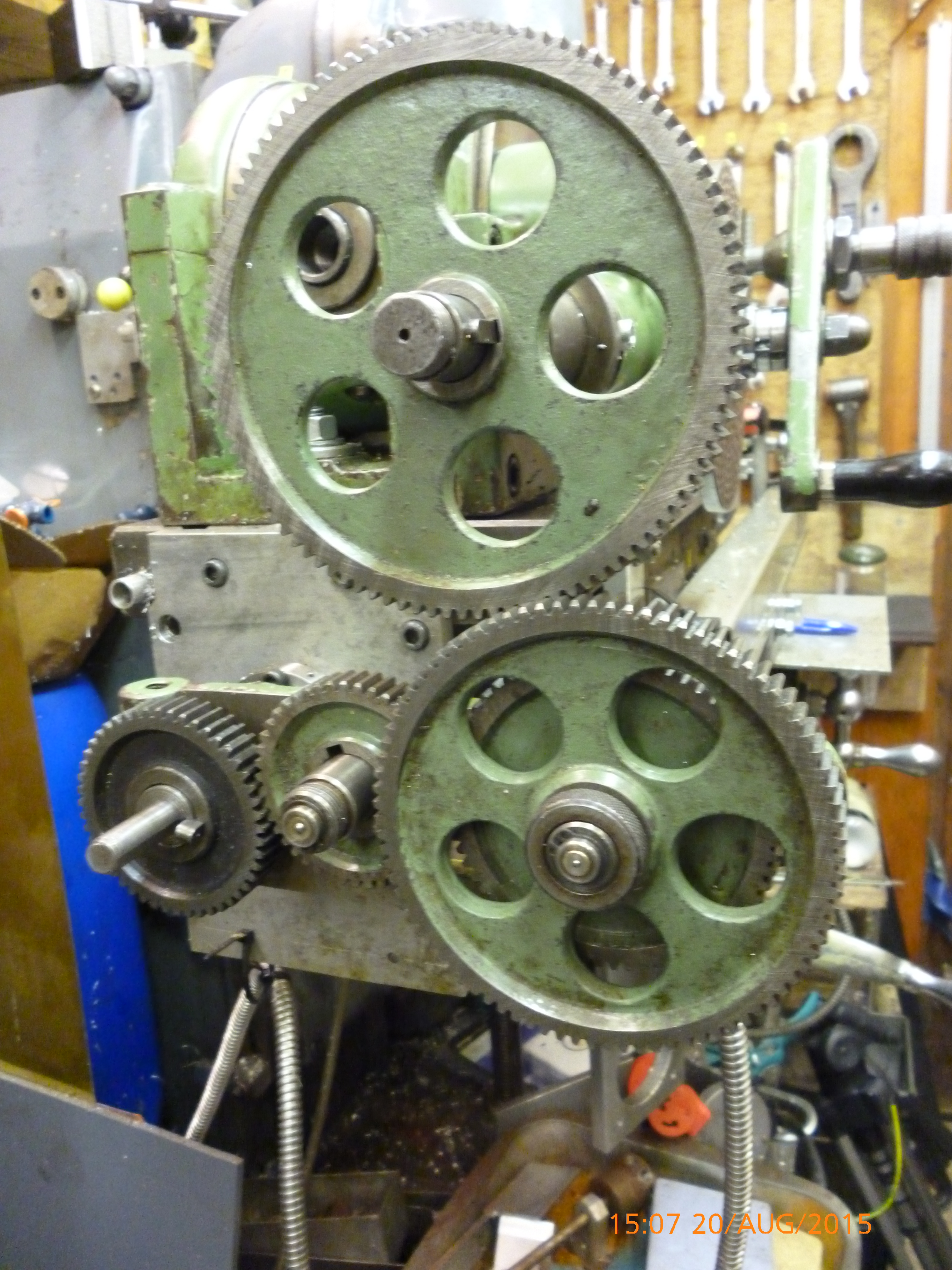
2474 gear train for cutting helical gear
Cutting the gear
In the setup shown below.
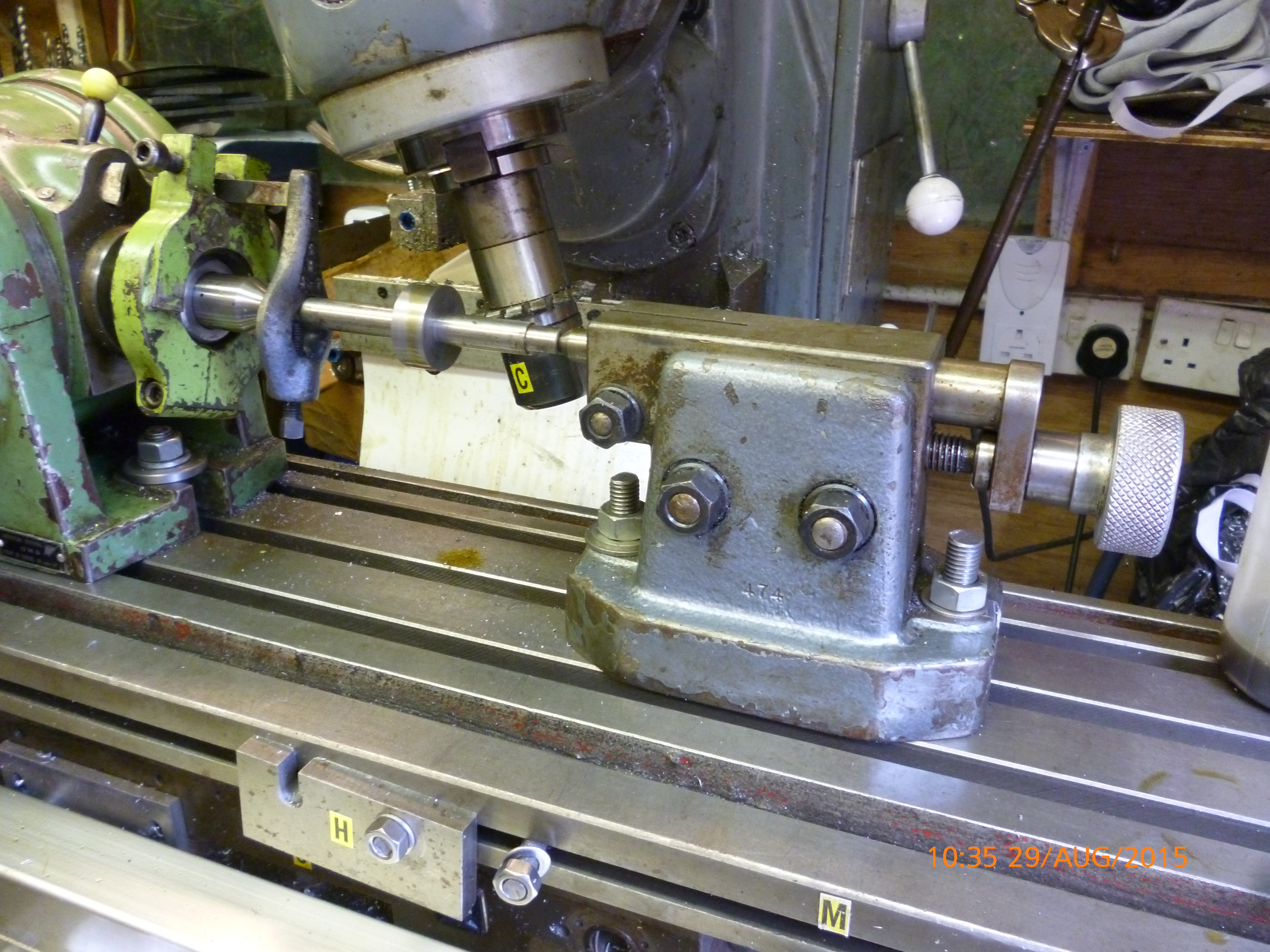
2492 cutting a helical gear
fig system setup for cutting
The cutter is set using cigarette paper to just touching the surface of the workpiece. The depth of cut required is 0.085inches. With the cutter to the right of the workpiece it is moved in by 0.085inches using the DRO. The DRO is then set to zero. All cut have to be made to this depth. It saves a lot of effort if a stop is set up so the depth of cut is always right.
The art of gear cutting is to make the cutting of each tooth a rigid, uninterrupted sequence that is continued without any stopping from the first tooth through to the last one.
The sequence is:
Set the cutter running
put some cutting fluid on the workpiece
feed the workpiece past the cutter at the right depth,
stop the cutter,
pull the table out so the cutter is clear of the workpiece,
rewind the table,
pull the pin out on the dividing head
rotates by zero or more whole circles if necessary
the pin will now be back inside the left sector arm,
let the pin into the hole
lift the pin out and turn so it touches the inside of the right sector arm
let it into the hole,
move the sector arms round,
move the table in till it reaches the stop,
back to the start of the sequence.
2470 cutting helical gear

2471 cutting helical gear
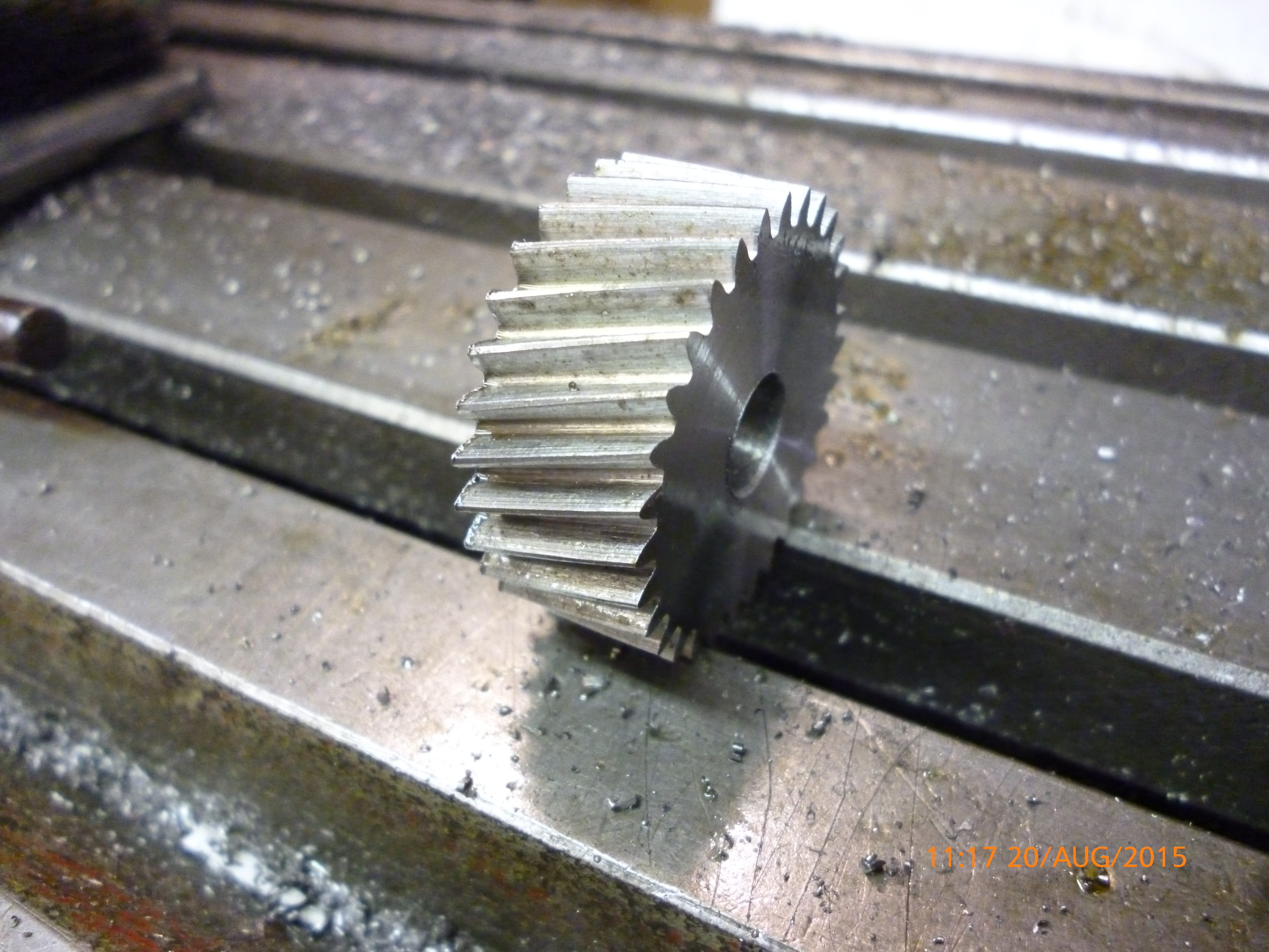
2472 finished helical gear
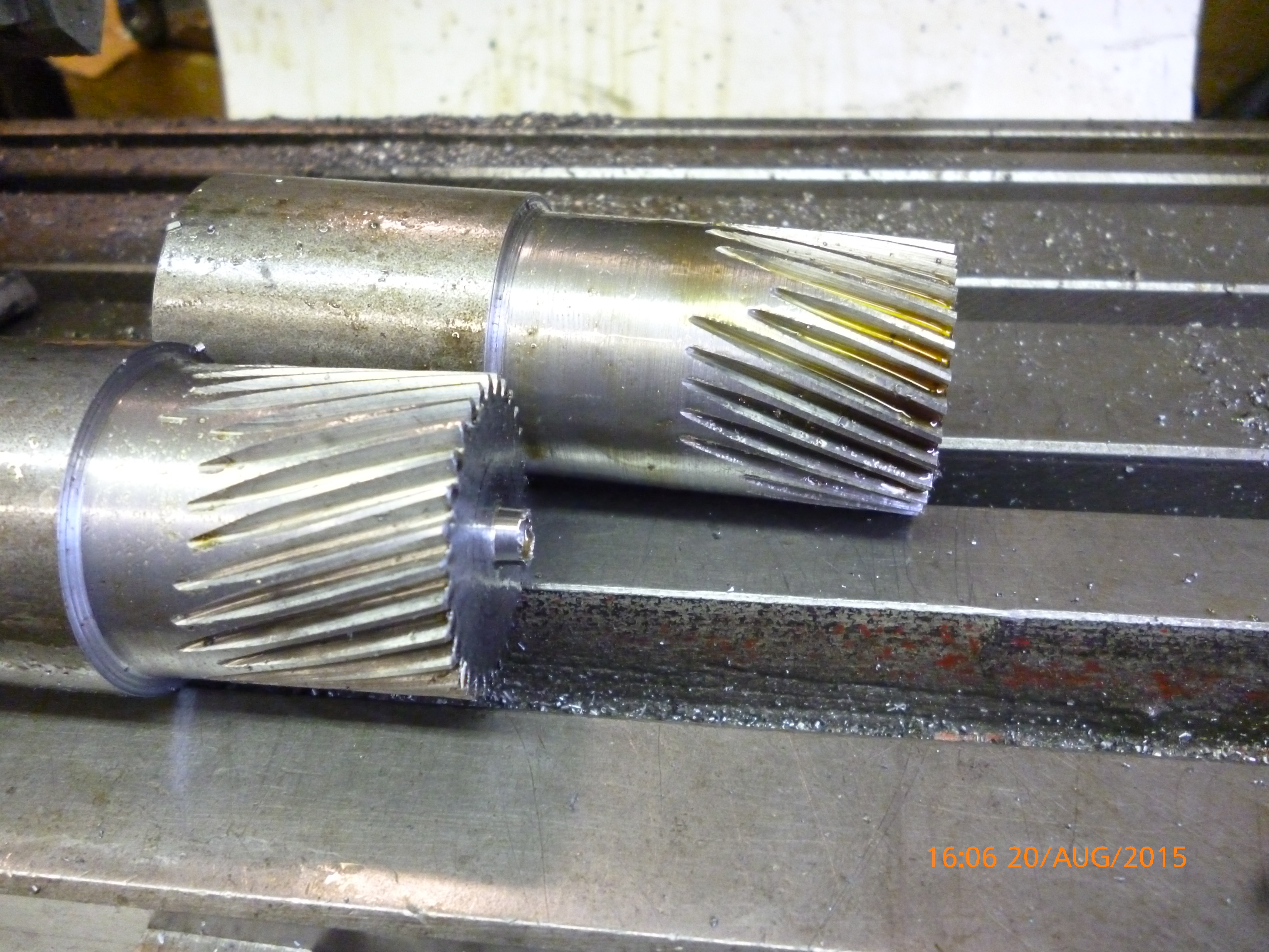
2475 left hand and right hand gears
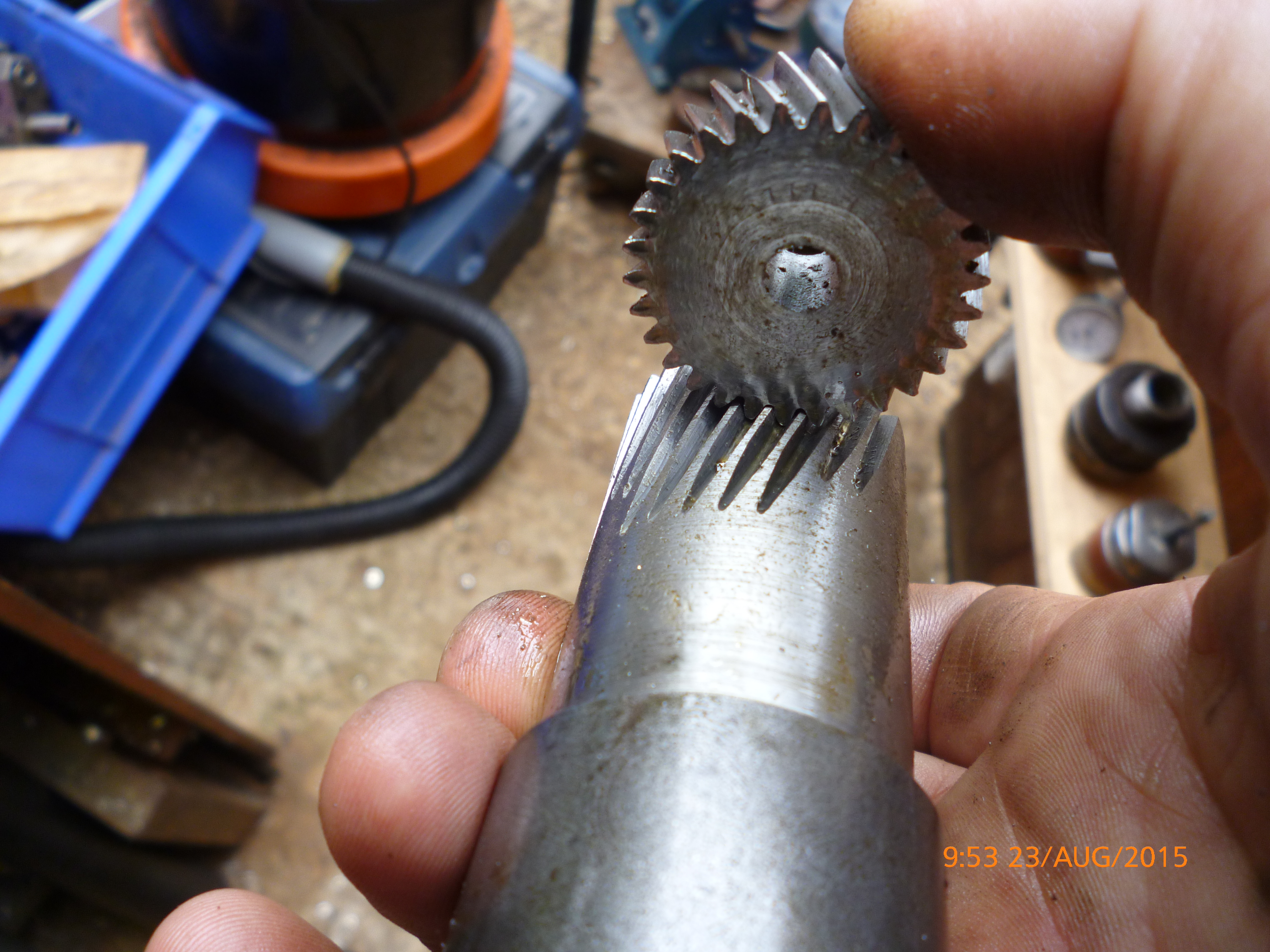
2477 left hand and right hand gears meshing
What is happening
The cutting is set running. It starts on the right of the workpiece. The leadscrew is turned so the workpiece goes past the cutter from left to right. As it moves right it also rotates.
After each flute has been cut the workpiece has to be moved away from the cutter. The relationship between rotational position between the workpiece and position of the table is only kept if the drive to the table is reversed. It is not possible to simply put the machine in reverse because any backlash in the system will mean the cutter will be dragged through the spaces but slightly wrongly. This is done till the cutter is back to the starting side of the gear. At any position the relationship is kept doing this. If this is done then, at any position, the pin on the handle can be pulled back and the handle can be rotated through the necessary number of holes.
There are close parallels between doing this to make a helical gear and cutting of a thread on a lathe. In both cases the machine has to run in reverse in order to retain the relationship between the cutter and the workpiece. But, in both cases, because of backlash the cutter would spoil the workpiece and so has to be retracted during the reversing stage. On the other hand, when make a spur gear there is no backlash and the workpiece can be rewound without withdrawing the cutter.
When the system has been rewound the workpiece can be moved back to the required position to cut the workpiece. The workpiece is rotated by the required amount, ie the spaces between the sector arms and the next cut can be done.
After the last tooth has been cut it is worth just doing one more cycle and checking that the cutter fits the first tooth that was cut.

Thankyou
Let me know how you get on.
john f
Can you cut the gear without the gear train
The usual methods available to the hobbyist are:
1 hob – needs specially modified jacobs gear hobber
2 cut tooth by tooth using a unversal dividing head ie using a gear train
3 using a simple dividing head that is fitted with a template wrapped round a drum fitted to the back end of the spindle
this engages a fixed tooth say on the vertical head thar drives the dividing head round
as the milling table moves along.
I think this is covered on my web site somewhere
john f
ty very mush on this sir . u give me an idea oh how to do this ryt
let me know if you have any specific questions.
john f
I need a helical gear made can’t find one is 16dp 10 tooth runs a rack gear on grinder do u cut gears thanks Myron Hawn mulehawn@gmail.com 828-729-4628
You can buy something like this from Hinchcliffe Precision Components for £12 plus vat and p and p but the helix angle is 17 45 and this must match that on your rack.
john f
Excuseme sr, I guess the cutter for a spur gear with 34 teeth is no 5. Not no 4. Very useful the explanation. Best regards
I dont know what bit of my text you are refering to but…
A spur gear is one with straight teeth ie is not helical 34 teeth would normally be no 4 which does 26-34. for a helical gear with n teeth then if m=n/cos^3(helix angle) then use the cutter for m teeth to cut n teeth. (check this yourself).
john f
I want to produce my own prototype that is a 90 degrees crossed helical geal. I have made my own calculation with a surprise. My finished part is 13 teeth and according to the calculation a need a gear cutter for 37 teeth. Is this procedure righ applicable for 90 crossed helical gear?. Am I in the right way? Thank you in advance. Best regards.
I suspect you are right. One way of checking is to look up a similar gear in a catalogue from a gear supplier. This will not though give you the size of the cutter but will give you all the other dimensions.
john f
I have a older Kenmore sewing machine with a broken feed dog helical cut gear. It is the only plastic gear in the machine and is unavailable. Can I ask if you would be interested in reproducing this gear.
I would cost less to buy a new sewing machine – however it is possible to buy gears ready made quite cheaply. These are made in vast number in many different sizes.
The last time I bought gears off the shelf was from Hinchcliffe Precision Gears in Chesterfield(?)
john f
to mike breen i have the exact same problem what was the solution
The usual methods available to the hobbyist are:
1 hob – needs specially modified jacobs gear hobber
2 cut tooth by tooth using a unversal dividing head ie using a gear train
3 using a simple dividing head that is fitted with a template wrapped round a drum fitted to the back end of the spindle
this engages a fixed tooth say on the vertical head thar drives the dividing head round
as the milling table moves along.
I think this is covered on my web site somewhere
john f
dear sir,
is there anyway to fabricate a spiral bevel gear on the same machine.
Sorry. I dont know.
I suspect that the best way of doing this would be to use a cnc machine with
a piece of software for making gears such Gearotic.
john f
effective blog
Thanks
This is the most popular page on my website.
john
hello can you help me how to calculate this if you have any table
Using Hobnail the gear train suggested (using a very limited set of gears) was:
100, 86, 64, 48
The whole point of hobnail is that it does the calculation – you don’t.. If you look carefully you will see it gives you the error these gears will give you. Try it with a calculator to check it.
john f
309.2 / 5= 61.84
40 / 61.84= 0.646
I am not quite sure what you are saying here.
john f
just a different calculation
Thiis was great to read