go to the page above this one
Dividing head
Some definitions of words used on this page:
A mandrel holds a workpiece by its bore. To do this either the mandrel is tapered and the workpiece is pressed onto it or the workpiece fits on the mandrel which is then expaned.
An arbor holds a workpiece by holding it across its end faces.
Holding the workpiece – intro
There are three main ways that a workpiece can be held when using a dividing head.
a It can be held on a tapered mandrel between centers
b it can be held in a chuck
c It can be held on a arbor or an expanding mandrel that is held in a chuck
In case “a” a tailstock has to be used. In cases b and c a tailstock might also be used if the length of the workpiece or arbor/mandrel is too long.
Holding the workpiece on a mandrel between centers
Most, larger dividing heads have a female taper in their spindles. This is can be used to hold a male center. The workpiece is mounted on a tapered mandrel. This is just a very accurately made round rod with female centers drilled in either end. One end fits a male center in the dividing head and the other fits the male center in the tailstock.
The mandrel has a nominal diameter, say, 20mm. But the body of the mandrel is very slightly tapered so one end will be a few hundredths less than 20mm whilst the other will be a few hundredths more than 20mm. Tapered mandrels are sometimes marked with a “+” sign showing the larger end. The workpiece has to have an accurately reamed hole in it exactly 20mm in diameter. The workpiece is pushed onto the mandrel using a mandrel press. The mandrel should be pressed in as hard as possible without using any extra aids. If the workpiece slips on the mandrel at all during machining usually the whole job will be ruined.
Since there is only one place on the mandrel, which tightly fits the workpiece, it is only possible to hold one workpiece at a time on this sort of mandrel. It also follows that a tapered mandrel should not be used for very long workpieces since their fit on the mandrel at the end where the mandrel is smaller will be significant.
The workpiece must be set up so the cutter pushes it towards the wide end of the mandrel.

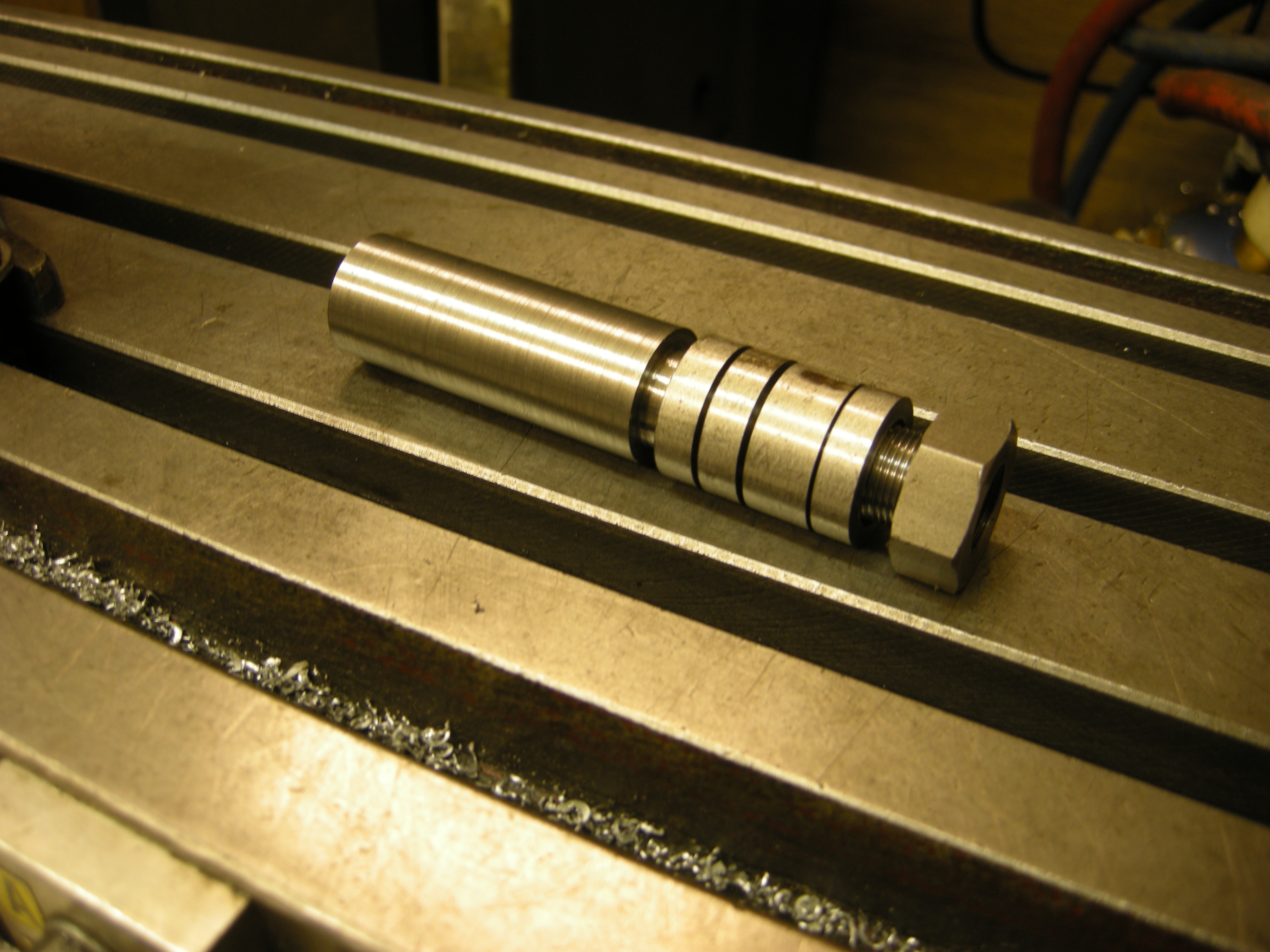
Tapered mandrels – 565
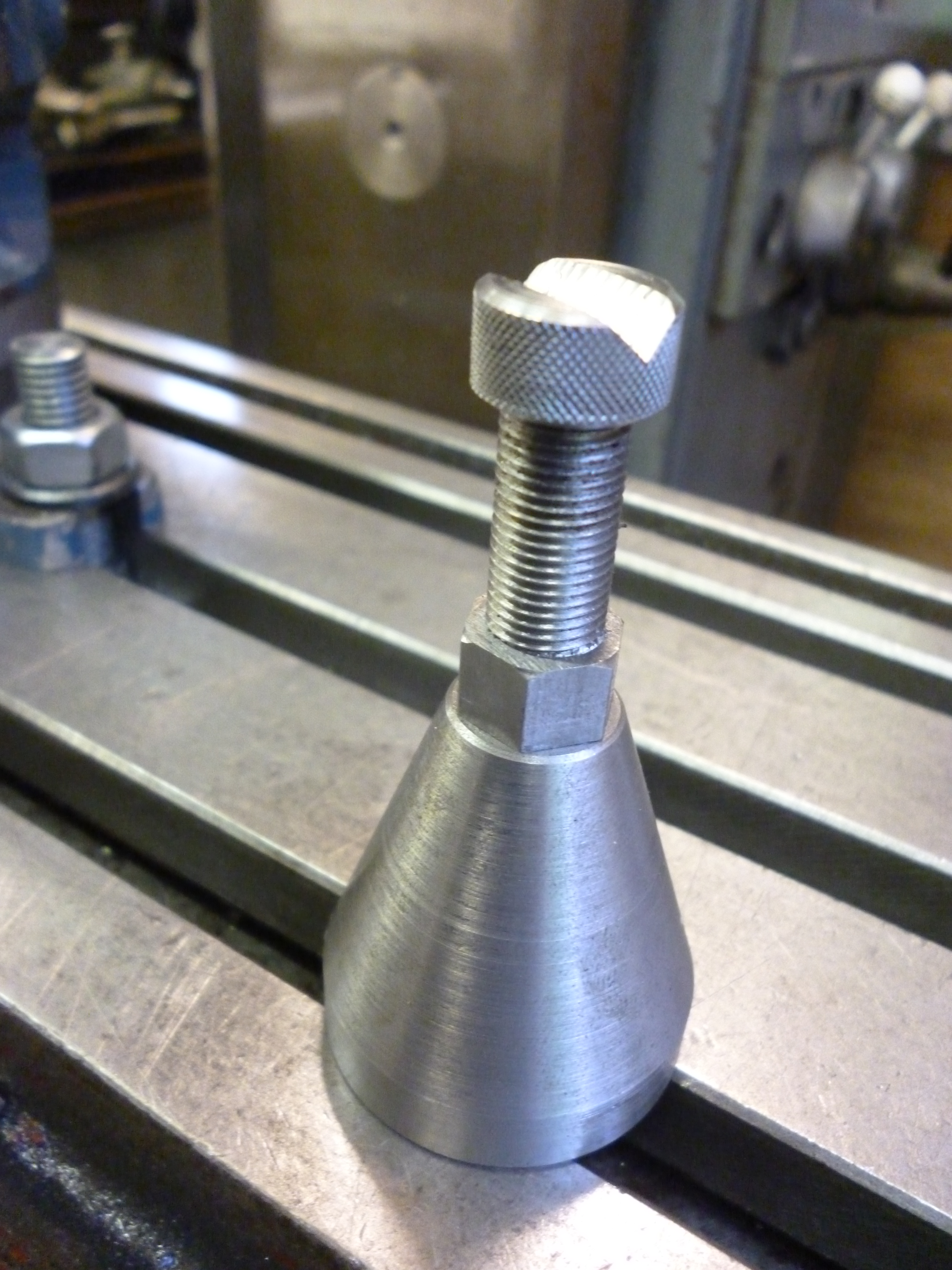
Expanding mandrels with steeper tapers, as shown, are not suitable as they cannot grip the workpiece tightly enough.

The wrong sort of mandrel – 580
The mandrel press
A workpiece can only be pressed squarely and firmly enough on a mandrel by using a mandrel press.

Mandrel press – 641
It will be seen that this is not just a ordinary press but there is a rotating plate with different size gaps in it. The mandrel with the workpiece is placed on this plate using the smallest gap that will fit the mandrel being used. There is also space for a bit more than half of the mandrel below this plate. The press is used to force the mandrel into the hole in the workpiece.
The dog
The tapered mandrel needs some mechanism to drive it round. This is done using a dog.

Modified dog – 372
This dog has been specially made so that the driver can hold it very precisely so that there is no backlash between the dog and the driver.
Most mandrels have flats at each end. The dog should be fitted so its screw fits on the flat of the mandrel. The dog then needs to engage something that will rotate when the dividing head rotates. This could be a catch plate mounted on the dividing head like the ones used on lathes. However there is a difference on the milling machine. On the lathe the workpiece is always being driven round one way. So the dog merely needs to be pushed one way. This does not happen on the milling machine so some way of locking the movement of the dog and the spindle of the dividing head is needed. One way is shown in Fig.

Dividing head driver – 303
This screws onto the spindle and has a screw mechanism to lock it in position. It also has a screw to lock the arm of the dog in position. When set up properly, if the dividing head is locked in any position, then the mandrel and workpiece will not move at all, rotationally.
There are drivers around that fit on a taper that fits into the spindle. These are not as good as the driver that is screwed onto the nose of the spindle. They will keep the center in the right position but they will not guarantee that the taper will not rotate.
When the job is finished the mandrel press should be used to remove the workpiece from the mandrel.
A tapered mandrel can only be used between centers. It would be possible to use any sort of parallel arbor between centers but in this case some method is required to ensure that the workpiece cannot rotate on the arbor.
Usually when cutting gears, for example, the cutter would cut whilst moving from the tailstock side of the workpiece towards the body of the dividing head. Naturally the wider end of the taper of the mandrel always points towards the dividing head so that the cutting forces will tend to force the workpiece onto the mandrel even tighter. If the dividing head is on the left of the milling table and the wide end of the mandrel is towards the dividing head and the cutter is a horizontal type cutter on a stub arbor in front of the workpiece then the cutter will have to cut in an anticlockwise direction.
Use of mandrels – Tailstocks
When a dividing head is being used to hold a tapered mandrel between centers a tailstock is needed to hold the far end of the mandrel.

245 A tailstock
It is, of course, essential that there is no play between the mandrel and the centers that hold it. A tailstock that does not have a screw mechanism to tighten the centers up, so there is no play longitudinally, is not really up to the job.
Tailstocks when dividing head is not horizontal
The shaft on small dividing heads is usually fixed in the horizontal position. On large dividing heads the body of the head containing the rotating shaft can be tilted either a few degrees downwards and upwards by just over 90º.
The standard tailstock can usually be adjusted by only a small amount. This is to allow for differences in height of the center of the dividing head when it is horizontal.
If the dividing heads is tilted then, if a tailstock is needed, the center on the tailstock should be in line with the center on the dividing head.
It is possible to emulate a tilting tailstock by mounting a tailstock on a tilting table. But even so the axis of the tailstock must be in line with that of the dividing head.

675 Tilted tailstock 1
With the above setup the maximum useable angle was about 15°. Even so it does not follow that any angle less than this is possible. This is because of the height of the tilting table even when it is flat.
If a wedge was used it soon becomes clear that only one angle is possible and this will only work for a mandrel or arbor of a particular length.
Tilting the tailstock by mounting it on an angle plate
A tailstock can also be tilted by mounting it on an angle plate. It can be seen from the photo that this is made much easier using an angle plate that is machined on the inside surfaces.
Fig tailstock tilted using an angle plate
Using a very long tilting table
The ideal solution to this problem is a tilting table that is long enough to mount both the dividing head and the tailstock and, of course, with the workpiece in between all on one flat but tilted surface.
Dividing head – use of a chuck
It is possible to have a chuck mounted on a taper that will fit the spindle of the dividing head. In this case a draw bar must be used to hold the chuck in place. The spindle usually has a thread on it so it is also possible to screw a chuck mounted on a back plate onto the dividing head. But whereas this will work on a lathe, if it always turns only in one direction, in this case it is essential that there is some mechanism to prevent the chuck from unscrewing itself.
Whereas on a lathe if a chuck holds the workpiece slightly off center it is often still possible to turn all the required surfaces so they are concentric to each other. This is not relevant when milling. If the workpiece has to be aligned accurately then it either has to be held between centers or centered accurately using a four-jaw chuck.
If the workpiece is long then it should have a center in it and should be held at the far end using a tailstock.
Dividing head – use of a chuck to hold an arbor
A chuck can be used to hold an arbor which then holds the workpiece.
365 arbor 2
Fig. An arbor 365
However well the arbor is made if the chuck is off center then the workpiece will be
The spacers are so that the arbor can be used for holding workpieces of different thicknesses.
If the arbor is long it can be supported at the far end using a tailstock.
Often, when using a lathe, a workpiece is held in the chuck during turning and then is parted off from the bar still in the chuck when finished. There is no reason for not being able to do a similar thing on the milling machine. But there is an important difference. It is far easier to remove the workpiece from this chuck and then to transfer it to a chuck on the lathe and then part it off just as one would have if it had been turned in the lathe.
Most jobs using a dividing head have to be accurately concentric. Many three jaw chucks are not accurate enough for this. Ideally if a chuck is needed on a dividing head it should be a four jaw chuck that so the workpiece or arbor can be accurately centered.
Expanding mandrels
fig expanding mandrel
The jack
If the workpiece is very long and thin it might still lack the rigidity necessary to make it machinable.
One solution to this is a steady. The situation is roughly similar to using a fixed steady on the lathe. Since the workpiece will often be being machined on the top surface all that is needed is something to hold it from moving down or from side to side. This can be done with a simple V-shaped block mounted on a screw which screws into another block, which rests on the milling table.
526b screw jack
Fig The jack
On the lathe the surface of the workpiece is often moving quite fast relatively to the steady so it makes sense for the surfaces of the steady to be made of bronze. On the milling machine the workpiece is usually still or moving very slowly so the block can just be made of steel.
Alignment when using the dividing head
Usually the angle of the dividing head can be set using the graduations on the dividing head.
The axis of the workpiece must be parallel to the milling table.
The axis of the workpiece must be horizontal, ie parallel in the horizontal plane to the milling table.
If the workpiece is being held in a chuck then a test bar can be fitted to the chuck. this can be set using a dti. This will mean the axis of the dividing head is parallel to the axis of the milling table.
If a tailstock is being used then when it is fitted to the end of the test bar it should still be correct if the height of the tailstock is right and if the tailstock is in line with the dividing head.
If a mandrel is being used then the dividing head should be aligned as above. It should then be fitted with a center. A test bar is fitted between the center on the dividing head and the center on the tailstock. This test bar can the be set so that its axis is parallel of that of the milling table.
