go to the home page
go to the page above this one
Rotary table – alignment with vertical spindle
When using a rotary table there are four simple steps that are invariably necessary. It is very easy to overlook the simplest alignments necessary. Most rotations will be with reference to some particular point. Usually this will mean setting the table to zero – the zero must be at the fiduciary mark.
Step One – Zeroing a rotary table
Before doing anything else with a rotary table it is always worth setting it to zero. The table is turned so the fiduciary mark on the base is pointing to 0 degrees on the side of the rotating part.
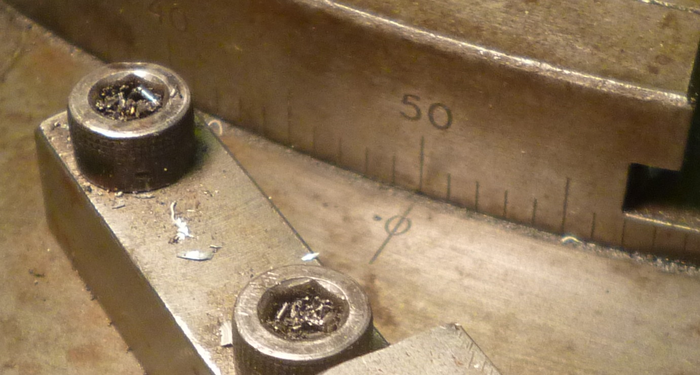
6101 setting zero on rotary table 3
fig setting the rotary table to zero
If this is done it is unlikely that the zero on the dial lines up with the marker. This can usually be adjusted by rotating the part with the calibrations on it whilst holding the handle from moving..

4408 setting zero on rotary table
fig 4408 setting scale on the handle to zero
Step two – “squaring” the rotary table
Sometimes it is necessary to make cuts into a workpiece mounted on a rotary table by moving the table in the clockwise or anticlockwise directions and it is necessary to align the table so that such a cut occurs when the fiduciary mark on the table is at a particular angle to the milling table.
In this case the next step is to clamp the rotary table to the table. It might not seem obvious but, ideally, a line from the center to the fiduciary mark should be at right angles to the table. This is not as easy as one might imagine.
This can be done with the tool shown.

691 aligning a rotary table
fig setting the rotary table so that it is “square” to the milling table
This device consists of a spigot that fits the hole on the rotary table. It has an arm fitted to it. One edge of this arm is aligned so it goes from the center of the rotary table to way beyond the edge of the rotary table. It has a clamp so it is bolted to the rotary table. It has a bit hanging down so it can be aligned at 270 degrees on the rotary table.
This arm can be aligned with the milling table using an angle plate and a square as shown above. The rotary table with the device attached is moved till it is square and is then clamped to the milling table.
On some tables the zero on the table can be adjusted. If so this has to be done when the rotary table is square to the milling table table.
step three – Aligning the rotary table with the milling table
If the rotary table has been “squared” then it will already be clamped to the milling table. In this case it is best centered using the DTI on an arm tool.
If it was not necessary to “square” the rotary table then it will not be bolted to the milling table. In this case the easiest way of aligning it with the spindle is by means of spigots.
The rotary table is now centered and aligned rotationally it is now possible to tighten the bolts up. Check the alignments still work ie the one in the milling chuck still slides in and out of whatever other spigot it is fitting into.
Four – recording the position
The final step in aligning the rotary table is to record the position by setting the x and y DRO’s to zero.
The table can be moved anywhere but it will always be possible to restore the centering by moving the table till the x and y readings are both zero.
Centering a chuck with the rotary table spindle – vertical
Whenever a chuck is mounted on a rotary table it will be necessary to align the rotary table at some point. Here the procedure is to align the rotary table as described above and then to fit the chuck as described next.
The easiest and quickest way of aligning a chuck on a rotary table is by using a spigot.
Firstly the chuck is mounted on a backing plate. This plate is of a larger diameter than the chuck and has slots in it so that it can be bolted onto the rotary table.

Fig rotary table/chuck adapter plate
Ideally the plate should be machined so it has a raised round part that will fit accurately into the recess on the back of the chuck. This is not to align the chuck but to make sure it is truly fixed in position. Where the chuck fits on this plate is not critical. The plate is bolted onto the back of the chuck. The plate has a hole in it so that the hole in the center of the chuck is exposed.
A spigot is made so that one end of it fits the hole in the chuck. The other end of it fits the hole in the rotary table.
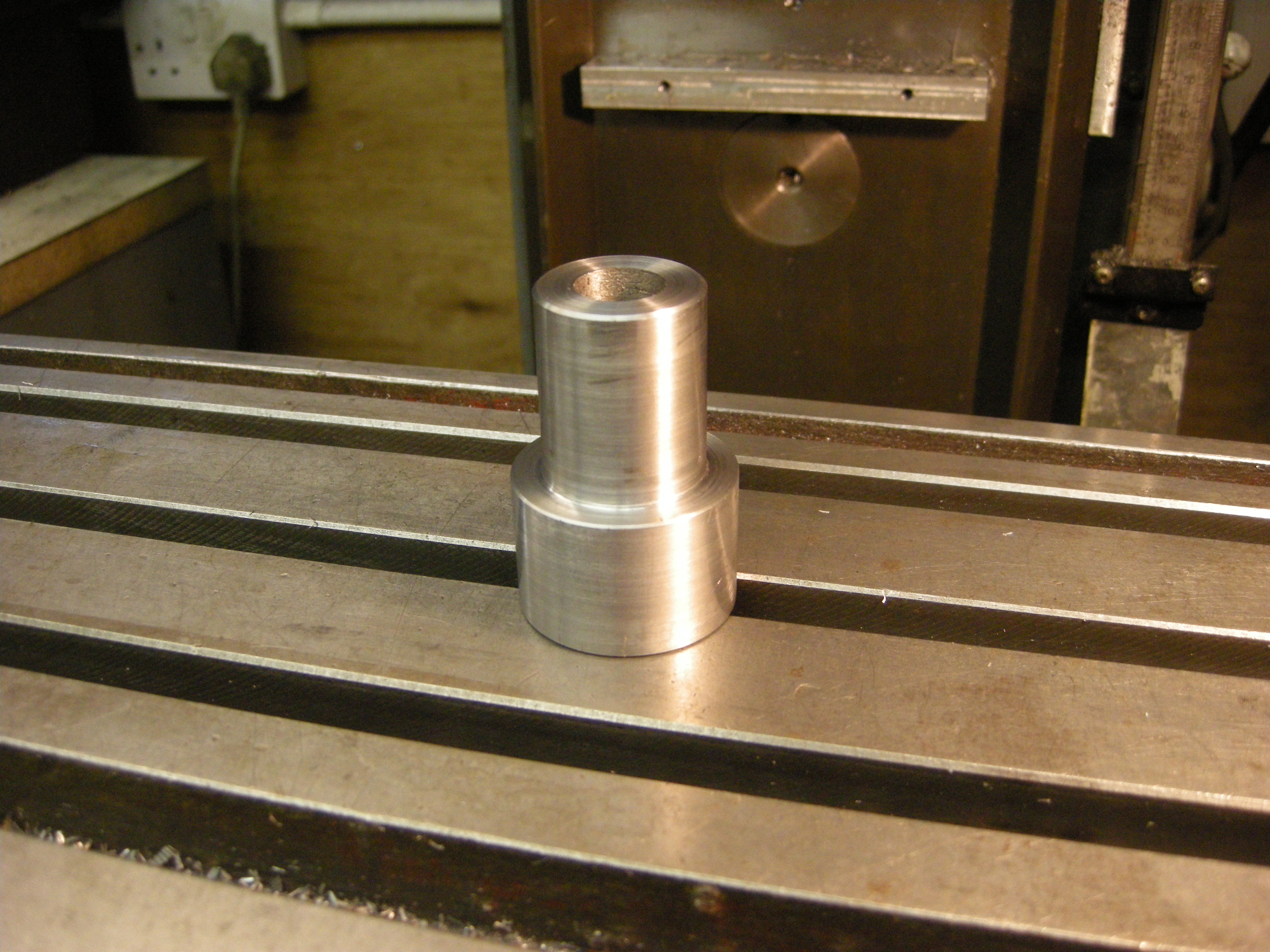
111 spigot 4
Fig. Spigot for centering a chuck on a rotary table 111
The spigot is fitted to the rotary table. The chuck and plate assembly is then bolted to the rotary table.
Fig chuck mounted on rotary table
Alternative method
The chuck with it backing plate is mounted on the rotary table loosely. A spigot is fitted in the jaws of the chuck. Remember the rotary table is aligned and locked so that it is aligned with the spindle.
The spigot in the jaws of the chuck is aligned with the milling chuck either by fitting into it or by using the DTI on an arm tool.
It will probably be necessary to make bolts specially to bolt the chuck/plate assembly to the rotary table. It is worth keeping them and the spigot(s) together with the chuck/plate assembly when not in use.
Aligning a rotary table in the vertical position
Aligning the workpiece on a rotary table
Having aligned the rotary table the next step is to mount the workpiece on it. This will need aligning relative to the rotary table’s center and its zero.
Centering round shapes or arcs on a rotary table
A workpiece might have several different radii to be cut on it, but with a common center. So the workpiece only needs to be centered once on the rotary table. But for every radius that has its own center, then the workpiece will have to be moved on the rotary table so the center of the required radius is concentric with the hole in the rotary table.
Most cases will fall into one of the following groups:
A – if the workpiece has a hole at the center of the radius to be cut.
Use a spigot to align the hole in the center of the rotary table and the hole in the workpiece.
Some rotary tables have some arrangement that allows for a bolt to be retained underneath the hole in the center of the rotary table. If this is the case then, if there is a suitable hole in the spigot, this can be used as one of the clamps.
B – if the workpiece is solid at the center of the radius to be cut.
Mark the center of the radius on the workpiece with a punch. Center the rotary table with the axis of the spindle. This means moving the milling table till both the readings on both the x and y DRO’s are zero. Lock in both the x and y directions.
Mount the workpiece so the center punch mark on the workpiece is on the axis of the spindle using a pointed wiggler.
C – if the workpiece does not cover the center of the rotary table
Make a spigot that fits the hole in the rotary table. Make a center in it using a spot drill in the lathe. Set a pair of dividers to the required radius. Set the workpiece so that whatever the length of the arc, the distance from the center in the spigot is the same to both ends of the arc. If the sector is not more than 90º use the two ends. If the sector is from 90º to 180º use two ends and the middle. If the sector is 180º-360º use the middle and two at 90º to the middle.
The height of the point of the divider on the rotary table should not be greatly different to height of the surface of the workpiece. If the height of the surface is significant then make the spigot so that the height of the top of the spigot is roughly the same as the surface being centered.
Centering the plane of angle plate surface to pass through axis of rotary table
The surface of an angle plate can be aligned with the center of a rotary table by making a spigot that fits the rotary table at one end. The other end has half of it milled away to give a surface that passes through the center of the spigot.
If the surface of the angle plate does not pass through the axis of the rotary table then as the rotary table rotates the position of all points on the angle’s surface will move.
It will be noticed that aligning a round workpiece has not been covered here because it is far easier to mount a round workpiece on a rotary table using a chuck.
Setting a rotary table and workpiece for a PCD
Very often drilling a circle of holes in a round workpiece would be done with an indexing chuck or a chuck mounted on a rotary table.
However sometimes a circle of holes is needed in a part that is not round or where the center of the circle of holes is not concentric with a circular part. Parts such as cylinder covers need a circle of holes but are not necessarily circular. In this case the workpiece might be clamped directly onto a rotary table.
Zero the rotary table.
See XXX zeroing a rotary table
Align the rotary table.
See aligning a rotary table
Center the rotary table and vertical spindle. Note the x and y coordinates.
See centering a rotary table
Lock the X and Y-axes.
Mount the workpiece on the rotary table.
This needs a center at the center of the circle of holes.
At the same time, the workpiece needs aligning with the milling table. One way of doing this is to clamp a long parallel to the workpiece along any reference line. The center is aligned with the spindle. The workpiece is rotated till the parallel is lined up parallel or at right angles to the milling table using the parallel, angle plate, square method.
Fig. Setting to rotational angle of workpiece on rotary table. 691
The workpiece is clamped to the rotary table. Unlock the x-axis. Move along the x-axis by the amount of the radius of the circle of holes. Clamp x-axis.
**** rotational alignment of workpiece
Setting a PCD
To set the pitch circle diameter the chuck rotary table combination has to be set so it is concentric with the axis of the spindle. The movement in one direction, probably the y direction is locked. The backlash in the x direction is taken up one way. The x dial or x-axis DRO is set to zero. Half the pitch circle diameter, in the direction the backlash was taken up, moves the table. The movement in the x direction is then locked.
Setting a angle plate so it is offset from center of rotary table
If the plane of the angle plate has to be off-center then use the spigot above and use a stack of slip gauges to provide the necessary offset.
Though this gets the distance right it does not ensure that the angle plate is at right angles to the radius from the center of the rotary table.
Setting the height of a chuck/rotary table on an angle plate
If the “vertical” rotary table is achieved by mounting a rotary table on an angle plate the it can be useful to have an angle plate that is machined flat on the inside angle of the angle plate. This can save space on the milling table.
Often the height needs to be set to a specific value. To do this fit a spigot, of a convenient diameter, to the rotary table. Place the angle plate with the rotary table loosely mounted on it on a surface plate.
If this assembly is “top heavy” then place it near the edge of the surface plate so the angle plate can be clamped to the edge of the surface plate using a toolmaker’s clamp. Place a stack of slip gauges of the height necessary underneath the spigot. Tighten the bolts holding the rotary table.
Check the height of the top of the spigot after the slip gauges have been removed.
Centering, with offset, two rotary tables
The centering of these is easier than one might expect.
The top rotary table is centered.
See
The work piece is mounted on it
A center is made in the work piece if necessary. This denotes the center of the top rotary table even after it is removed from the milling table.
The bottom rotary table is mounted and centered as above.
The y-axis is locked
The table is moved in the x direction by the required offset.
The top rotary table is placed (i.e. not bolted) on the bottom one and centered relative to the vertical head.
All of this is positioned so that the cutting tool is the radius of the arc to be cut from the axis of the large rotary table. The milling table is then locked in both the x and y directions.
The start and end points of each arc are simply determined two angles on the bottom rotary table. How many slots there are and where they are determined by the angle of the top rotary table.
Aligning a workpiece on a rotary table
Spigot with center and dividers
DTI on arm
