Methods for finding edges
What is commonly called “edge finding” is really a matter of aligning a point on a workpiece with the axis of the vertical spindle.
Cigarette paper
Cigarette papers used for roll-your-own cigarettes are cheap and easy to buy and are made very accurately to about 1 hundredth thick. There is more than one thickness available so check the thickness of the ones you are with a micrometer.
If a paper is wetted by placing it on the tongue it will stick to the side or top of a workpiece – if it is clean, that is, not oily. As the cutter approaches the cigarette paper it will suddenly snatch it. With care this can be done without marking the workpiece. But the cutter will then be within one thickness of cigarette paper from the workpiece.
Of course, at this point, the axis of the spindle is half the width of the cutter away from the surface. (If edge finding)
If the DRO is set to zero and then moved in the right direction by half the width of the cutter and then set to zero again the reading on the DRO will be the distance of the reference edge from the axis of the spindle.
An interesting feature of the cigarette paper method is that it is the only simple method of finding an edge in the z direction.
An advantage of this method is that the cutter does not have to be removed from the spindle to do this.
Sticky pin
The sticky pin is just a pin stuck onto whatever is fitted to the spindle. It does not matter if it is coaxial with the spindle. It works because the point of the pin will only be stationary if it is coaxial with the spindle.
If a pin is stuck on the end of, say, an endmill it will be off center. If it is rotated the end will rotate in a circle. Take a ruler, horizontally, and gently push it against the tip of the pin. It will soon get to a position when it is stationary as it rotates. When this happens, this point lies on the axis of rotation of the spindle.
It does not require changing the tool because it can just be stuck on the end of the tool. But this does reduce the maximum height of the workpiece.
Wiggler
This is a superior form of sticky pin. It consists of a shaft with a ball joint at one end. It usually comes with several different arms that can be fitted to the ball joint. But the most commonly used end is another ball.

209 wiggler in use
The wiggler will fit an ordinary collet chuck or drill chuck but it will not fit an Autolock chuck because it does not have the necessary screw thread on it.
The center line of the shaft of the wiggler does not have to be very accurately aligned to the axis of the milling spindle to get good results. If the wiggler is rotating and the workpiece approaches it, the wiggler slowly straightens up. Then all of a sudden the wiggler flips completely out of line. The most reliable point that can be used for edge finding it just after it has flipped. Allowance has to be made for the diameter of the ball or whatever else is on the wiggler’s arm.
Once the wiggler flips it has actually gone past the edge. For the most accurate result, it is necessary to work out the position at which it starts to flip. This means making it flip a couple of times at least and noting the point just before the flip.
This is usually accurate enough for most work. however it is said that better accuracy can be achieved if instead of using fact that the tip flips at a certain point, this point is found by looking at the space between the surface and the wiggler with a bright light behind the gap.
Wiggler on curved surfaces
If the wiggler is used on a round surface whether it is an internal or external surface it will behave to same way. It will straighten in exactly the same manner as before. Regardless of the angle at which it touches the workpiece the wiggler’s center will be exactly in line with the spindle. In this sort of case it is not necessarily easy to compute where the workpiece is relative to the spindle.
Usually, where a curved surface is involved it is necessary to find an extreme point on the surface, for example, the left most point of the curve.
For a convex surface this can be found by “scanning” the ball to and fro across the surface whilst at the same time moving the workpiece towards the wiggler. It is easy to find the extreme point because it will be seen that this is the first point where the ball appears to touch the workpiece. Also, when it is about to flip, the knocking of the ball against the workpiece, which can be heard, will stop.
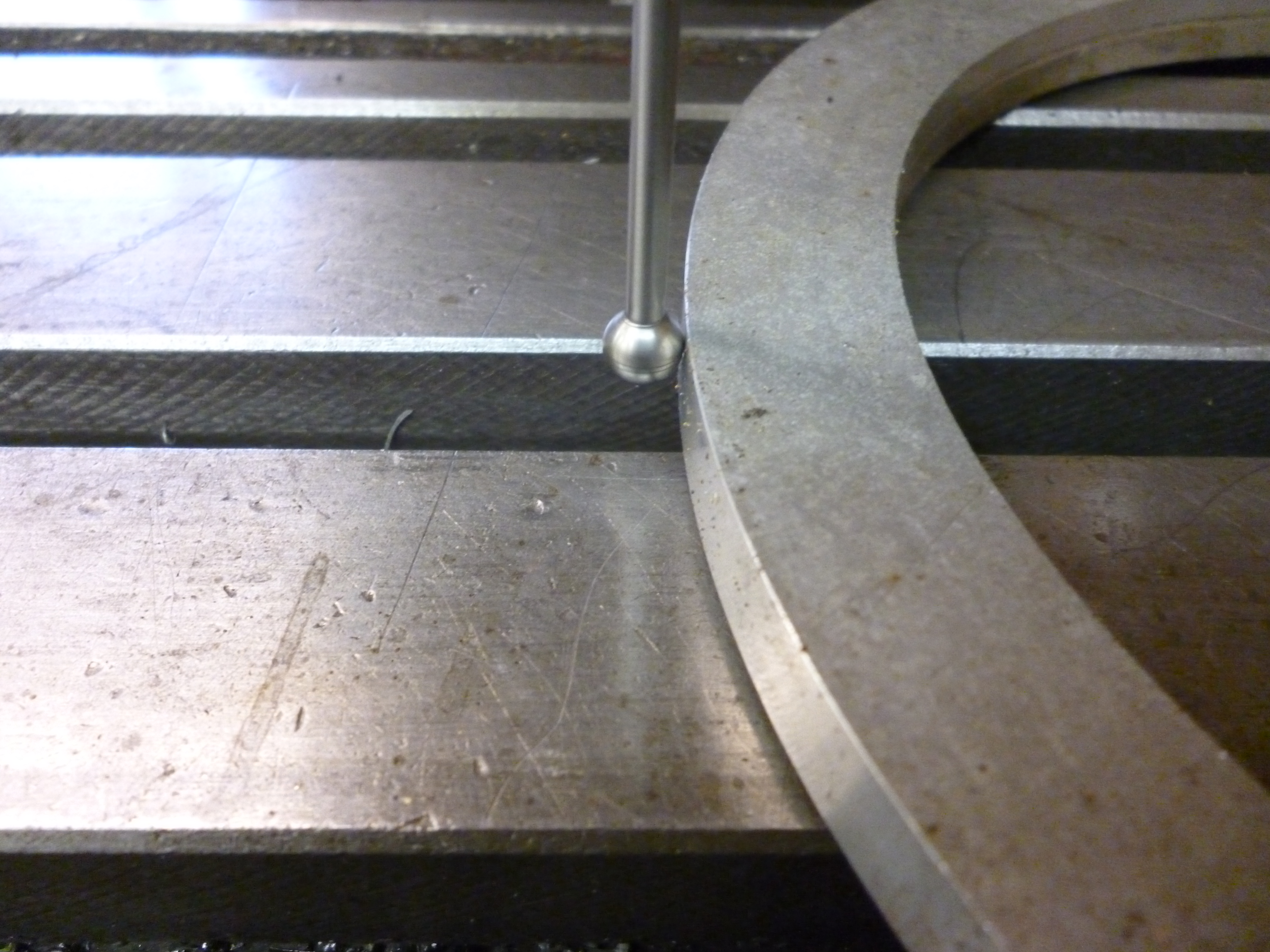
537 wiggler on a convex surface
For a concave surface because at any point other than the extreme point it will flip but it will do this prematurely. It is really a trial and error process whereby the extreme point is slowly arrived at more by a process of elimination.

538 wiggler on a concave surface
This has the opposite problem. The extreme point is the only point where the wiggler cannot be move left or right without hitting the edge. In a sense it cannot be found directly. It can only be found by noting where it is not and making a note of the reading on the DRO.
Up to a point, the faster the spindle is rotating the shorter the time between the movement of the table and the point at which the wiggler flips. Hence, for a given speed of movement of the table, the faster the spindle, the more accurate the reading.
Wiggler accessories
A wiggler is often sold with a set of other parts. These are:

330 wiggler accessories
The small arm with a ball on one end.
This is useful for finding the edge of a flat, vertical surface. If we know the diameter of the ball we can work out where the edge of the workpiece is relative to the axis of the spindle.
The small arm with the small cylinder on the end
For detecting the side of a round shaft the wiggler should be fitted with the arm that has a short parallel end to the wiggler arm. This is because there is no being sure that a wiggler with a ball touches the shaft exactly at its extreme point.
Bent arm with ball on the end
This can be used to center round shapes either on the inside, i.e., a hole or a solid round shape. It is not rotated under power but by hand. It is very difficult to adjust. The dovetail arm with the DTI (see later) does roughly the same job but is much easier to adjust.
Bent arm with part for holding a DTI
This is like the bent arm with the ball on the end. But it does not have to be adjusted so accurately as the arm with the ball on it. It is simply turned by hand and the workpiece moved till the reading on the DTI is the same in left x position, the right x position and the near y position.
Arm with a pointed end
If a workpiece is marked out in the traditional manner and the center of the holes to be drilled are punched with a center punch it is sometimes necessary to align such a punch mark with the spindle of the milling machine.
One way is to mount the wiggler in the spindle and to fit it with the arm with the point on it.
It is quite easy to use an edge, like that on a ruler, to center the point so that clearly is not moving as the spindle rotates.
A punch mark can be centered by moving it till the point of it is in the center of the punched center.

547 aligning a punch mark
Electronic edge finder
An electronic edge finder is just a gadget that makes a circuit when a piece of metal touches the workpiece. Since the workpiece and the whole milling machine is a conductor the sensor has to be insulated from the milling machine. The edge finder also has to be concentric with the axis of the spindle. The usual arrangement is that when the circuit is made an LED in the edge finder lights up.
Fig. 140 – electronic edge finder
This is like the wiggler in that once contact has been made it will have gone past the edge.
Depending on how the probe is made it can be possible for a probe like this to detect the “edge” of a horizontal surface.
See MEW 157 p24
Mechanical edge finder
This consists of two round parts held together by a spring. This is fitted in the spindle. The spindle rotates. If the two parts are offset as the workpiece approaches the bottom part, it tends to line up with the top. As soon as the workpiece goes beyond this point the bottom part jumps to one side.
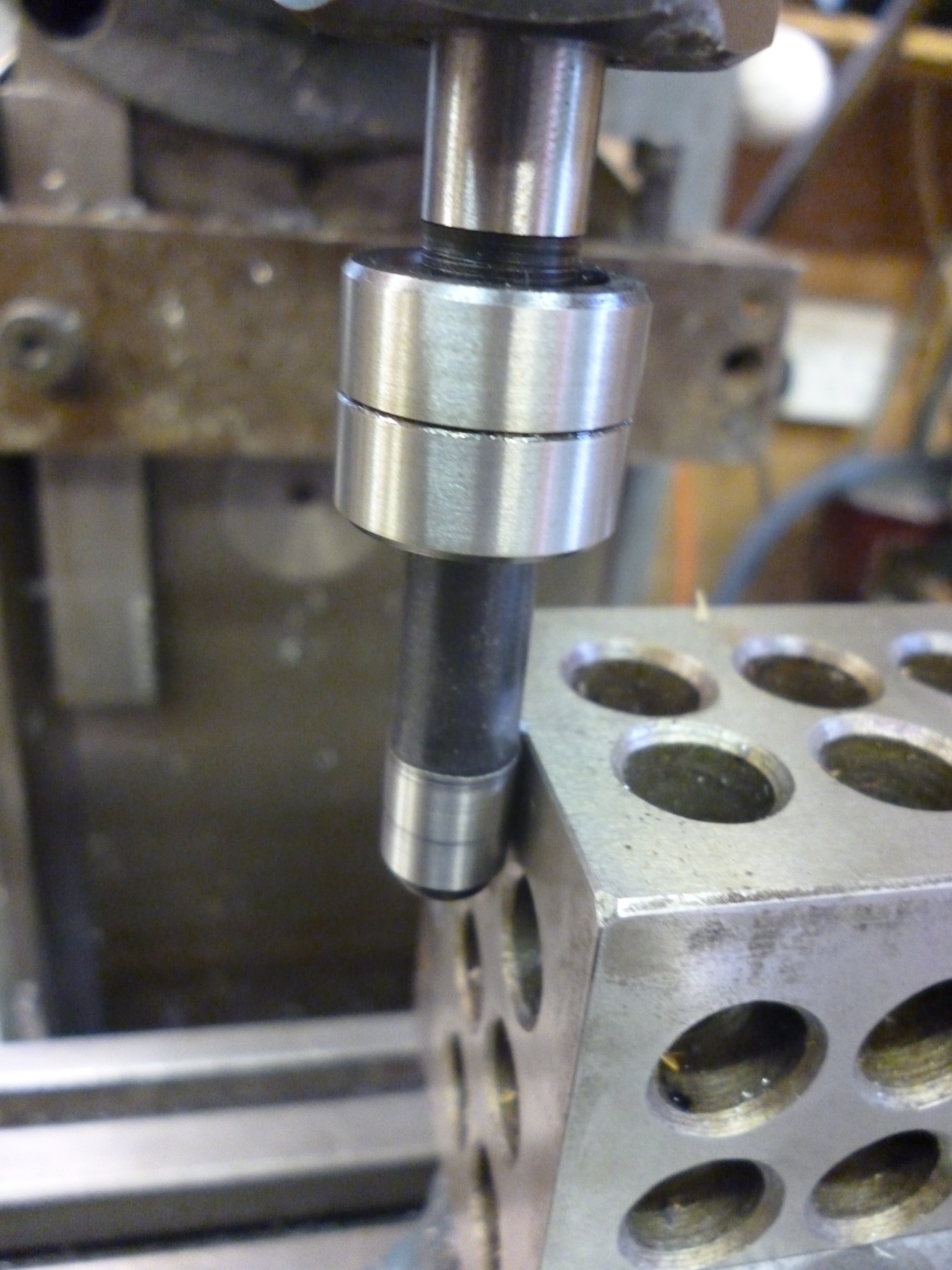
47 edge finder just touching
Fig. 141 Edge finder just touching 47

46 edge finder after touching
Fig. 142 Edge finder just after touching 46
Unlike the wiggler the top part of this has to be centered with the spindle.
The centering microscope
The centering microscope fits the socket in the spindle. It contains some cross hairs that have to be aligned so the center of the cross hairs is on the axis of the spindle. This only has to be done once. Thereafter whenever it is fitted to the spindle the cross hairs will show exactly where the axis of the spindle is on the workpiece.
If it is used a lot it is much more comfortable if the eyepiece slopes upwards rather than being horizontal. A simple microscope produces an image that is upside-down and back to front. It is also much easier to use if the image is the right way round and the right way up.
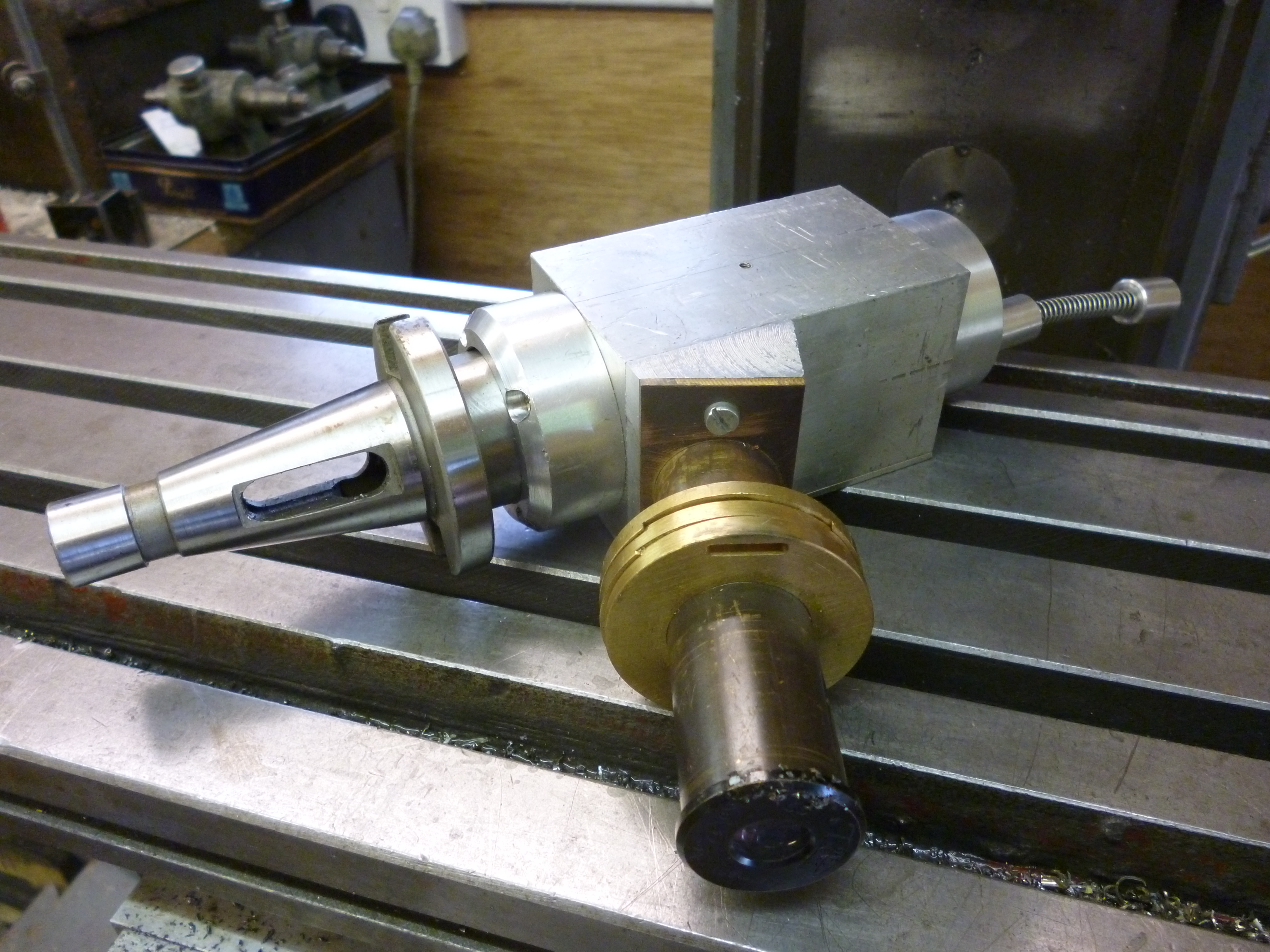
210 centering microscope 4
The round part round the objective lens contains four LED’s for lighting up whatever is being observed.
One advantage of the microscope over all other centering devices is that it magnifies the image. This can often be an advantage. But too high a magnification becomes a liability.
This can be used to find vertical edges or points on the edges of holes or any other shapes.
Simple microscopes cannot measure angles directly. If a part is being reverse engineered the trick is to measure all of the points of interest including those that define any necessary angles. These points are then used to make a drawing using a CAD program. It is then easy to get this program to fill in the missing lines and work out what the angles are.
The probe on the end of the spring is the plane where the image being looked at will be in focus. The distance that any image is in focus is only a few millimetres deep. But this is not accurate enough to determine the height of an object.
mew no 106 p44
Mew 111 p52
Webcam – 1
The Webcam centering tool is simply an ordinary webcam fitted to a taper that fits into the taper of the spindle. The only important requirement is that the whole assembly is rigid.
Fig. 144 – webcam fitted to vertical spindle
The crosshairs are created by software. If the spindle is aligned on a pair of crossed lines on a workpiece then the cross hairs are simply placed in this position. Thereafter the web cam can be installed and removed any number of times and the cross hairs will still be correct.
Fig. 145 webcam display on computer
If the socket for the spindle is the same as for your lathe it can be fitted to the tailstock on a lathe. It can then be used for centering workpieces in the chuck on the lathe.
The Webcam is the only simple method that can be used to measure angles directly.
Centrecam mike trethewey
http://www.miketreth.mistral.co.uk/centrecam.htm
mew no 112 p18
Mew no 121 p21
This software does not always work and this site does seem to have been updated for a very long time.
Webcam – 2
If cross hairs cannot be created by software then they can be made by using some mechanical means. Any system with just one lens will have just one focal plane. For the crosshairs to be in focus they must lie in this plane. But, of course, at the same time the the object being looked at must also lie in the same plane ie the one the crosshairs are in. This is not very convenient.
some gadgets sold as digital microscope actually have just one lens. This has just one focal plane. It is possible to put some cross hairs here and it will be in focus. It is then possible to add a second lens. This will produce a focussed image but further away than the crosshairs.

You appear to have found the page I was thinking of. The explanation of the wiggler is here. But I cant see anything about a dti and slip gauge on this page.
john
John,
I w under the impression that you were giving different examples of finding edges and holes, and I noticed you made no mention of dti’s at all to achieve this subject, so I thought I would ask, I come from the old school before electronic and ground edge finders, then we mostly used the dti for most things sometimes a wobbler,
this subject relates to the old fashion way as in die making and finding two corner edges to use for datum for say a die plate or stripper plate in the toolroom, (this was before edge finders) all dimensions usually came from the X and Y corner and the use of a dti and a ground pad as in maybe a slip gauge was used to find these edges, it was more accurate than the (wobbler wriggler), it enables you to accurately align the jig borer spindle centre line exactly on those two edges, the principle was to rock the stylus to find highest point and zero set it , then turn the dti 180 and place the gauge against the ground edge with finger holding it and rock the stylus and adjust that axis until the dti reads zero in both positions, I know it sounds tedious but its not really, the Moore Jig Borers had a special tool with a small magnet that rested on the edge and on top there was a rectangular aperture with faces ground exactly on the centre line of the tool and they then swung the dti 180 deg and adjusted the axis, just like finding the centre of a bored hole, that was available for the rich, the description I am describing was for the poor little die shops, it achieved the same results though,
Edmund………..Alberta
On this page the problem is aliging a point on a straight edge. I assume a dti or some other method was used so the edge is parallel to the x or y axis.
What you might be thinking of is aligning a round part so the center of the round bit is coaxial with the spindle of the milling machine. Somewhere I have device that uses a dti on an arm to do this. I was displaying the actual thing at the midlands model engineering show just a couple of weeks ago.
john
search for dti on dovetailed arm.
john