Aligning the vertical head – tramming
One of the key alignments on a vertical milling machine is setting the vertical head so that it is square with the milling table. This has to be so it is square in the x-z plane and in the y-z plane. All vertical heads, except on the smallest machines, are designed so that they can rotate in the x-z plane. This is a very useful feature. But, of course, if it is used then the head has to be realigned afterwards. Some heads can also be rotated in the y-z plane. Again, if this is done then the head will have to be realigned in this plane afterwards.
A similar problem is where the head is not designed to rotate in the y-z plane but is not perfectly square when tested.
The process of setting the head so that it is square is known as “tramming”.
Consequences of misalignment
If the head is misaligned in the x-z plane then any rotating point on a cutter will cut deeper on one side that the other. This will be true whether the workpiece is moving from left to right or from right to left. If an endmill is being used instead of leaving circular marks it will leave “C” shapes facing left to the left or facing to the right. If this can be seen it is a fairly certain sign that the head is not aligned. If the workpiece is milled with an endmill with a series of parallel cuts in the y direction each cut will have a slight slope and will have a ridge that can be felt with the finger.
If a wide cutter is used such as a flycutter in the x direction then the surface will have a very shallow curve to it.
If the head is misaligned in the y-z direction and an endmill is used to cut in the x direction in a series of cuts then a series is very shallow slopes will be formed..
If a flycutter is used to machine the whole surface from left to right in one pass then the surface will be flat but will be at a slight angle to the bottom surface of the workpiece.
Tramming
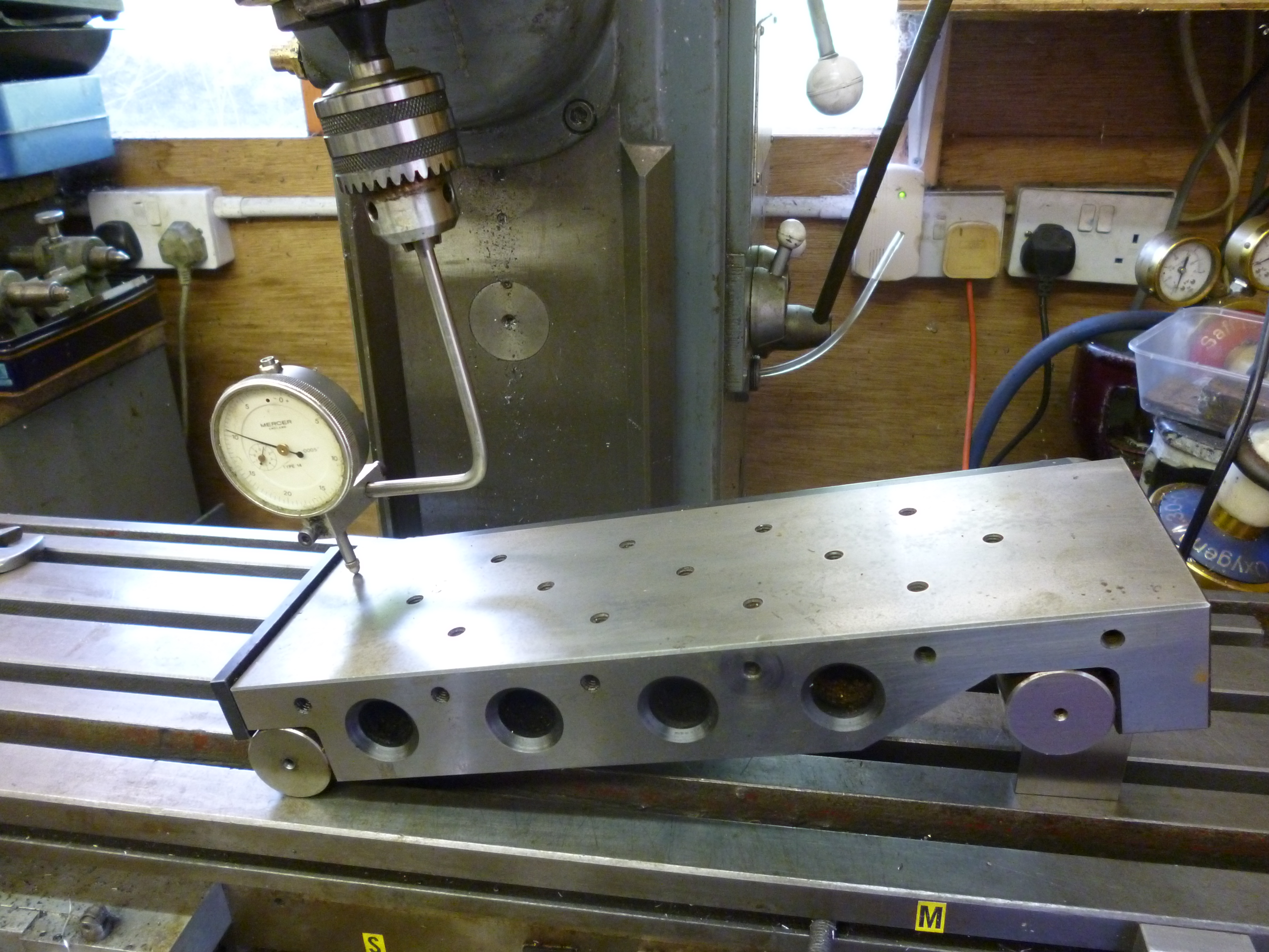
The most accurate way to check the alignment of the head is by tramming. This can be done by fitting a DTI to the spindle as shown. The rod can be any that fits the DTI. It can be fitted to the spindle using a drill chuck or any collet chuck. The accuracy of the chuck, in this case, is irrelevant.

92 tramming
If the head is square then the reading on the DTI should be the same when the arm is to the left as it is when it is to the right.
If the table of the milling machine was just a flat surface it is easy to see that as the DTI is rotated it should read the same whatever the angle of rotation. But there are the T-slots. The ideal solution to this is to have a flat plate that can be placed over the t-slots so the DTI can be rotated without the interruptions of the slots. However, the smallest ding anywhere under this plate will cause any readings to be unreliable. Another way of doing this is to use a sheet of paper. This is placed on the table covering the area that could be touched by the DTI. When the DTI is at a position of interest the sheet is slid away from under it. Having read the DTI the sheet can be slid back again. This can be done over and over again without applying any force to the DTI.
If the readings at the left hand and right hand positions are the same then the head is aligned in the x/z plane.
Heads that rotate or not in the y-z plane
Similarly, if the head rotates in the y-z plane then the readings in the front and back positions should be the same. The head should be adjusted till they are.
What if the reading are not the same and the head cannot be adjusted?
Usually the head can be removed from the column.The simplest problems is if there is dirt in the join between the head and the column. alternatively the surface at this join could be spoilt. this could happen if a screwdriver was used to force these surfaces apart.. This might have caused a ding on one of the surfaces. If this does not solve the problem it might be the bolts that connect the two part were not tightened properly. It might be found that adjusting the tightness of these bolts might solve the problem.
Otherwise place small pieces of shim in the joint. Use some soft metal so it is more compressible. In extreme case fit soft, copper washers on all of the bolts that hold the two surfaces together.
Setting the vertical head at an angle
If the head has to be set at an angle then the procedure is the same except that instead of the dti touching the milling table it is touching a sine bar. The sine bar is set to the required angle.
55 tramming vert head at angle
fig

Nice page John, just found it when looking for info on spiral milling.
Is this the correct method for tramming the head?
What if the the table isn’t perfectly trammed, then the result is table and head not trammed, but readings are zero.
Shouldnt you put a bar in the spindle and then put an indicator on the table an move the table up or down Weile indicator follows along bar to tram the head?
Greetings,
Peter from The Netherlands
This is the only method I have ever seen mentioned. Many suppliers produce gadgets to do this, this way.
I dont think what you are suggesting would be as reliable and accurate and easy to do.
I cant remember what I wrote on this page but it has occurred to me since that the device I describe for centering a round workpiece with the vertical head uses a dti with a lever but the same device with a plunger dti could be used for tramming.
John f
I think if you tram the table first, it can be done this way indeed.
Otherwise, like your example with the sine bar, you can tram the head at an angle because the table is at an angle.
P.S. The method I described is in the Deckel FP manual.
Greetings,
Peter
Im not sure what you mean by tramming the table first. This would only be necessary if the table had some means of tilting along the x axis which I have never seen. There are mills which tilt along the y axis but these are relatively rare so I have not mentioned it. I also only write up what I have done for myself and my mill does not do either of these.
On the other hand, it is quite common for horizontal mills to have swiveling tables which is essential to do helical milling with the mill in horizontal mode.
If the table tilts then I would think this has to be done first then the head can be trammed.
If the table needs to be trammed all that is needed is a plunger type dti fitted to the vertical head and the table is moved in the x and or y directions as needed. Notice the head is only a fixing point – this will work even if the head is tilted.
Let me know what you think.
john f
Ah, now I understand. I was talking about a universal milling machine. Like the one I have (Deckel FP2)
Indeed, when you cant set the table at an angle you can tram the head to the table which should be straight.
Greetings,
Peter
It seemed to that in almost all british or american sources no milling machines have tables that tilt in the x or y directions.
horizontal machines might have a table that swivels about the z axis. This as far as I can tell, is usually what is referred to as being a universal machine.
Incidentally what is often called “spiral” milling I have called helical milling partly because it actually produces helices and partly because I do cover producing real spirals which are completely different.
john