Back to home page
Back to previous page
Points applying to most types of dovetail
Holding the workpiece
If the workpiece, ie the male or female part, is too big to be held in a vice it can be clamped to the milling table. The part could be milled from a rectangular block that has already been machined so the four sides are flat and square to each other. Alternatively, the part can be made from from a less accurate block so long as one of the larger sides is flat. This can be done using a fly cutter in one pass.
This surface is face down on the milling table. But the workpiece is supported on parallels. These are clear of the sides. This means the sides can be machined along with the dovetail surfaces without moving the workpiece. This means all the surfaces that matter will be parallel. The workpiece is clamped using a fence at one end and one or two side clamps at the other end.
Usually the long sides of the parts will be parallel to the sides of the milling table if they are already machined and roughly so if they have not been.
The word “parallel” has a slightly special meaning here. How can the two sides of the dovetail be parallel? They are parallel in the sense that if one considers the top of the dovetail part as a flat surface then the lines formed where the sides of the dovetail intersect with the top must be parallel.
Holding the workpiece – using a vice
If the workpiece is small enough a vice can be used to hold it. In this case the fixed jaw of the vice must be parallel to the milling table. The bottom surface and the side surfaces of the workpiece must be flat and square.
Usually the long side of the part will be parallel to the jaws of the vice.
Angles used on dovetails
In most of the different types of dovetail that follow a dovetail cutter is used to cut the angled surfaces on both parts of the dovetail. Where a dovetail cutter is used to make a dovetail it is invariably used in the vertical socket in the vertical position. Doing this means that the angle on a dovetail is defined by the angle on the dovetail cutter used to make it.
On large industrial scale machines the angle is usually 45º. For smaller dovetails the usual angle is 60º. Any less than this, i.e. 60° on a small machine, complicates the design of the adjustment mechanism. The angle produced is set by the dovetail cutter used. But other angles can be used and dovetail cutters exist to do this.
Getting the best possible finish on a dovetail
The final cuts on the touching surfaces should be done to give the best possible finish. This reduces the friction as the surfaces slide against each other. The best possible finish is obtained by making only a fine but real cut, using the sharpest possible tool, at the highest speed and the slowest feed rate. For the final cut all feeds not being used should be locked. Some sort of cutting fluid should be used (or not) depending on the metal being cut – nothing for cast iron, paraffin for aluminium and soluble or other oil for anything else.
Material for dovetails
Large dovetails such as those on a machine are invariably made from cast iron castings. It turn out that cast iron on cast iron is a good combination.
For jobs where smooth movement is not important steel on steel works.
For very small dovetails brass on brass or brass on steel is often used.
Lubrication of dovetails
On all machines such as lathes and milling machines it is always recommended that sliding surfaces should always be oiled – not greased.
However, on very small dovetails such as those found on microscopes it usually seems that they are greased. The grease is often very thick. It is as if the function of the grease is to deliberately introduce friction so as to prevent movement unless the operator actually wants it to happen.
Dovetails – matching the outsides of the male and female parts
On many dovetail, when the two parts are fitted together, the sides of the male part are in the same plane as the corresponding sides of the female part.
There are people who could measure these so the outside of the male part matches the outside of the female part as part of a greater plan. For those who don’t measure, can’t measure or get it wrong either way, there two ways of matching the sides.
First, make the female part wider than the male so that wherever the two parts end up the female part is wider than the male on both sides. When the dovetail has been completed and this includes fitting the gib and locking it, mark where the edges of the male part come on the female part on both sides. Then machine the female part down to these marks.
Second, if both parts are roughly right one way or another, fit them together and lock them. Put them together in a vice and machine them together. Do this, this way the full length of both parts must be machined to get the same finish all over.
Doing this means the dovetails surfaces are machined at one setting and the sides are machined at a another setting. Yet it is essential that the dovetail surfaces are parallel to the sides. The only way of doing this is that when machining the sides like this that the dovetail surfaces are set so that they are accurately parallel to the axis of the milling table.
It is essential that the vice is aligned perfectly with the milling table for all operations during the making of this dovetail. Otherwise the sides might match when they at one position relative to each other but might not when at any other position.
Controlling dovetails
Many dovetails are used because one part of a system has to be moved very accurately relative to the other part. This is usually done by means of a leadscrew.
There are two ways of doing this. On many milling machines there are examples of each of these.
First
Consider the milling table, which is the male part fitting a female part underneath. The handle and bearing are fitted to one end of the leadscrew and fixed to one end of the milling table. The nut on the leadscrew is fitted to the female part. Traditionally, the convention is that as the handle turns clockwise the table moves away from the handle. If the leadscrew and nut have right-handed threads then as the handle is rotated clockwise the table moves towards the handwheel.
For this to work properly this needs a left handed thread on the leadscrew and the nut.
Second
Consider the milling table and the female part underneath it. All of this is fitted to the knee or the base of the milling machine. The hand wheel is fitted to the knee. The nut is fitted to the underneath of the part under the milling table. If the thread is right handed then as the handle is turned the table moves towards the handle – the wrong way. A left-handed thread is needed. This is what is normally provided.
On cnc machines ball screws and ballnuts are used. Since the hand of the leadscrew can be sorted out with software only right handed ballscrews and ballnuts are made. If these are fitted to a milling machine that is used manually then the y-axis table feed will be the wrong way round. But the x axis feed will be the right way round.
Usually this means that the middle of the male part of the dovetail is milled away to provide space for the leadscrew.
Locking dovetails
Though the whole idea of a dovetail is that the two parts can move relative to each other, there are times when is essential that they can be locked together.
Where the dovetail has a gib of the screw adjusted sort, one way of doing this is to replace one of the adjustment screws with a grub screw. This can be tightened to lock the movement with an Allen key.
With a tapered gib, assuming the taper has been properly adjusted, it would be very undesirable to touch this adjustment. But an extra screw, rather like that on the screw adjusted gib, could be used to lock it.
Small dovetails that rely on a “perfect” fit can be locked by using a grub screw that acts directly on the male part. In this case it is essential that there is a piece of softer metal between the end of the cap screw and the male part of the dovetail.
Perfect fit dovetail – 668
Fig. Screws for locking a gibless dovetail 668
Notice that there are no lock nuts. The grub screws do not act directly on the surface of the dovetail. To do this would damage the surface. Instead there is a small bronze part shaped to fit the dovetail then the grub screw. One of the bronze parts can be seen to the left of the assembly.
Crossed dovetails
It is a common requirement to make a table that moves in both the x direction and the y direction. This is usually done by making two dovetails which are at right angles to each other.
The bottom component is often a male part as is the top component. This leaves one middle part with two female dovetails cut in it at right angles to each other.
The method of making this is when the workpiece is set up to cut the first dovetail one edge of the workpiece is machined to produce a reference edge exactly parallel to the dovetail. Suppose this dovetail was machined along the x-axis then when the workpiece is turned over and rotated through 90º, the reference edge must set to be exactly at right angles to the x-axis of the milling table. Then the other dovetail can be machined and this will be at 90° to the first.
Fig. cross dovetail – common part
Of course, not only must the dovetails be at right angles but they must each lie in a plane that is parallel to the plane the other is lying in. This means, at the very least, that the top and bottom surfaces of the workpiece must be parallel before starting to cut either dovetail.
Crossed dovetails – where the milling table swivels
The above procedure assumes that the milling table does not swivel. If the table does swivel then the accuracy of the “squareness” of the cross dovetail will be exactly that of the alignment of the swivel table at the time of doing this job.
see aligning a swivelling milling table
Alternatives to a dovetail
V-shapes with rollers
The conventional dovetail described above is usually driven by a leadscrew. This can be powered by hand or an electric motor. In either case the friction caused by the touching surfaces is acceptable. If some for some reason this friction is too great it is possible to form a sliding mechanism but instead of the dovetails the two components have two pairs of V-shaped slots. It is possible to either use ball bearings or roller bearings which greatly reduces the friction.
Many devices where the loads are very light, such as those used for optical systems, use slides which use ball bearings.
Where the loads are higher it is possible to use roller bearings. A system using this is to be found on the Clarkson tool and cutter grinder. Similarly where the need for precision is high roller bearings can be used. Such a system is used on the high precision Mitutoyo height gauge.

625 clarkson roller slide
Fig. Clarkson tool and cutter grinder slide mechanism 625
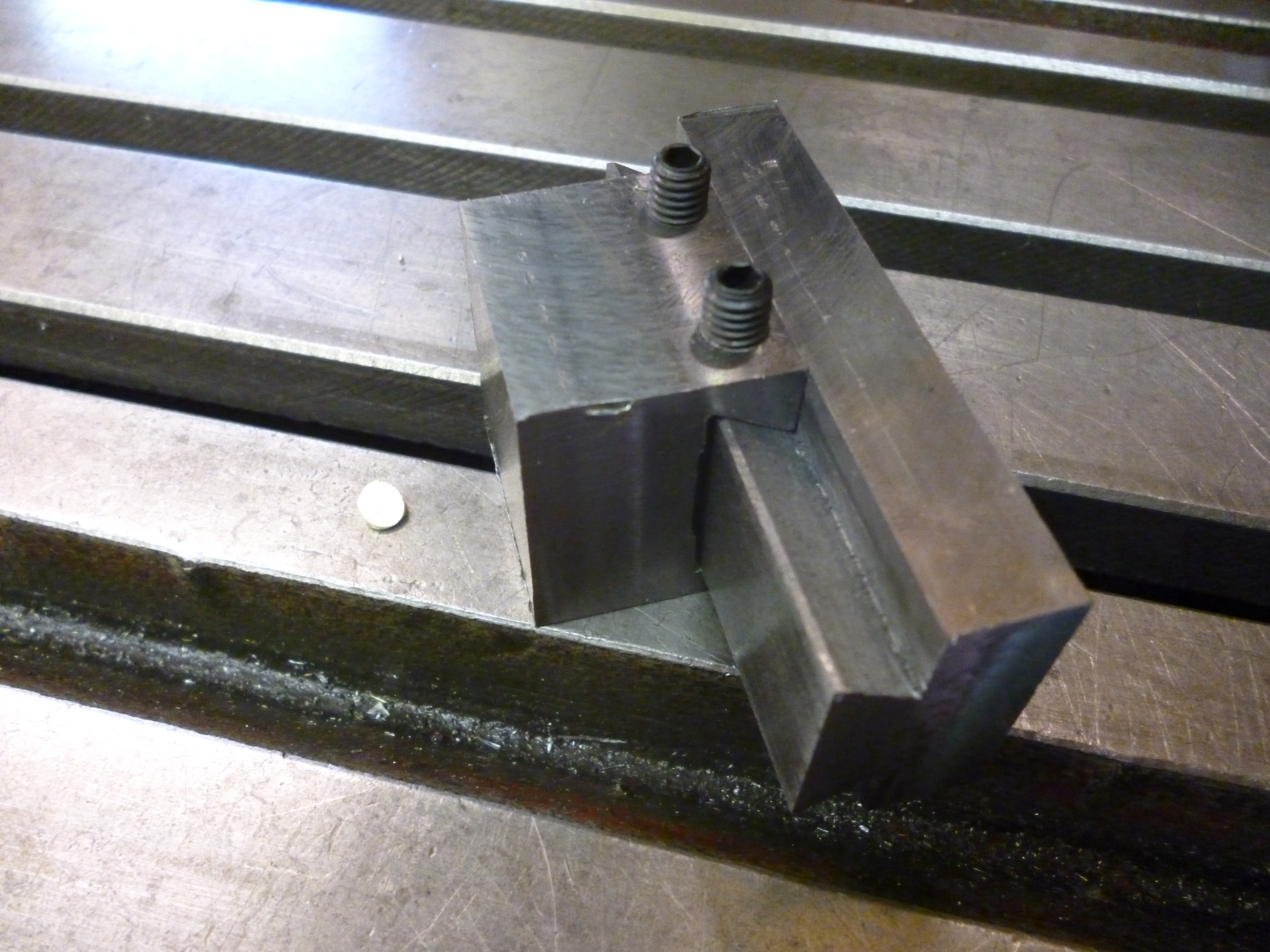
Fig. – drawing of “dovetail” using roller bearings – 1055
The two outside parts of the dovetail are the square parts with screws on the ends. The inside parts are on the green painted casting and also have similar screws on the ends.
In between these V-shapes are roller bearings. There either have to be enough balls/rollers to guide the V’s over a sufficiently long distance or a lesser number held apart in a cage.. The screws on the ends are to stop them rolling too far.
To make a slide like this is very similar to making a conventional dovetail. Again, the critical point is the two internal V’s must be parallel and in the same plane. Since this is just like the internal part of a dovetail the method for making it is the same.
The workpiece is clamped to the table and parallel to it. But, as will be seen, the cutter cannot cut low enough so the workpiece has to be raised on parallel blocks.
The cutter is a horizontal type cutter used for cutting 90° V-shaped slots. This is held on a stub arbor held in the vertical socket.

438 machining v slots
Fig. machining a pair of parallel V-slots 438
It will be noticed that in this case a cutter normally used in the horizontal mode is actually better used in the vertical mode since in this way it is possible to machine both slots without moving the workpiece – hence ensuring parallelism.
The workpiece has had to be raised on to 1-2-3 blocks because even with the cutter at the end of the stub arbor the end of the arbour is still very large.
The outside parts of the “dovetail” cannot be cut easily because of the distance of the cutter from the end of the stub arbor. It is possible to cut these as two separate V’s that are bolted onto a flat surface to form the outside part of the dovetail.
It is usual on machines that involve grinding to arrange that the slides are completely enclosed to protect them from the abrasive dust.
Making dovetails without using dovetail cutters
It is quite possible to make dovetails without a dovetail cutter. There are two main ways of doing this. Firstly the head of the machine can be tilted. Secondly, the workpiece can be tilted.
One advantage of doing this is that any angle can be chosen. The main disadvantages are that the longest length of dovetail that can be cut might be more limited and that more care needs to be taken to ensure that all the surfaces that need to be parallel are parallel.
Dovetails made by tilting the workpiece
With a plain milling vice, surfaces at odd angles can sometimes be machined by holding the workpiece at an angle in the jaw. However workpieces are usually held in the vice so that the long length lies across the width of the vice.
A dovetail is always cut along the length of the material. To cut this in a vice, could be done using a dovetail cutter. This would be very similar to cutting a dovetail where the workpiece was clamped to the milling table. This has already been covered. Instead of turning the workpiece we can tilt the vertical head. Doing this the workpiece can be held across the width of the vice.

524 making a dovetail using a tilted vertical head
Since most vertical heads only tilt left/right the cutting has to be done along the y-axis. Movement in the y direction is always less than in the x direction but it can still be enough to make useful dovetails.
This works because, so long as the workpiece is not moved in the vice, the dovetail surfaces will be “parallel” so long as the top surfaces are machined flat at the same time.
The dovetail is cut using an endmill or slot drill. One side is cut with the head tilted one way. Then the other side is cut with the head tilted the other way.
Before starting to cut make sure that the head can make the first cut tilted one way and then the second way without changing the position of the workpiece on the milling table.
Cutting with a very small endmill can often lead to inaccurate surfaces due to the cutter bending. In this case once most of the material has been cut away, a very small final cut should be made with a slightly bigger endmill very slowly to get the most nearly accurate surface.
Whereas a dovetail cutter machines two surfaces in one go, in this case the endmill only machines one. The other can be machined using an ordinary endmill – preferably at the same setting. The endmill does cut away a bit more than is needed but it makes no difference to the operation of the dovetail.
On not using a tilting vice to make dovetails
If the dovetail is short then the workpiece can be held in a tilting vice and each side of the dovetail is cut using a small endmill. Since most tilting vices only tip up but not down it is only possible to cut one side of the dovetail. To do the other side of the dovetail the workpiece has to be turned round in the vice. The two sides of the dovetail will only be parallel if the vice is exactly at right angles to the x-axis of the machine.
Since the material of the dovetail is probably quite thick it is possible to machine a dovetail that is 50-100% longer than the length of the jaws of the vice using this method.
This could be used for making the Colchester type of dovetail but only the female part. Otherwise this method cannot compare with using a dovetail cutter.
