go to the home page
go to the page above – dovetails – links
Dovetail – first type – with a gib
The first type of dovetail to be described consists of two parts. These are the internal dovetail (the male part) and the external dovetail (the female part). The adjustment is made by means of a gib that is used to adjust the fit between the first and second components. This is the gib.

dovetail with gib – 286
With the following method it is possible to cut a dovetail whose length is up to the travel of the table movement in the x direction less the diameter of the dovetail cutter.
Maximum length of dovetail that can be made
Furthermore it is almost impossible for the sides of the dovetail not to be parallel to each other and of the correct angle. For a dovetail to work properly it is not only essential that the sides are at the right angles but that the flat surfaces that are in contact must also be perfectly horizontal.
The key to success is to machine all the surfaces on each component that matter with just one setting of the workpiece.
Drawing for dovetail 1
On the male part surfaces A’ and D’ are in the same plane. B’ and C’ are at the angle being used for this dovetail to surfaces A’ and D’. It is essential that surfaces B’ and C’ are “parallel” to each other. Here, this means that the lines formed where they intersect with surfaces A’ and D’ must be parallel. In practice this simply means they must be machined at the same setting as the surfaces that form the dovetail.
On the female part, surfaces A and D must be in the same plane. If a parallel gib is being used it actually only necessary for one pair of surfaces B and B’ or C’ and C to mate properly. In practice it is no more difficult to make sure both of these pairs mate up. Obviously the “width” of the male part must fit into the female part. It is also essential that the depth of the male part is just less than the depth of the female part.
Usually on the female part the cut will be symmetrical on the workpiece, ie, within space F.
Apart from the angled surfaces that mate the two pairs of horizontal surfaces a and a’ and D and D’ also mate.
It will be noticed that there are three pairs of horizontal surfaces, A and A’, B and B’ and E and E’. It would be difficult and totally unnecessary to get all three pairs touching. Usually it is the outside pairs, A and A’ and D and D’ that touch. But Eand E’ do not. But it is possible to make dovetails like this but the mating surfaces are just the inside pair, E and E’. An example of this is to be found on many vices.
Dovetail on vice – 234
Dovetail as often implemented on vices
The above drawing shows the arrangement of the dovetail as shown in the photo above. The gib has been left out for simplicity. notice in this case only the middle surfaces touch whereas in other dovetails only the outer surfaces touch.
Dovetail – type 1 – Making the male part – outside surfaces touching
It is absolutely essential that both sides B’ and C’ are parallel.Also A’ and D’ must be in the same plane. But, it will be seen that all of the important surfaces will be machined at one setting of the workpiece. For the male part all that is required is that two cuts are made on each side of the top surface. This means that the middle part is not machined. Therefore this part can be clamped here and all the machining for the dovetail can be done at one setting.
The easiest way of making a dovetail is to clamp the workpiece along the length of the table. The section should be clamped to the table so that one edge is parallel to the table.
It is also possible to clamp the part to the milling table using “side” clamps but these are used on one end of the workpiece. The other end is held against one or more fences.
See
It is quite possible to machine the sides at the same time if the whole piece is mounted on parallels. In this case regardless, within reason, of how parallel the workpiece is to the milling table, all of the surfaces that matters will be parallel.
If a gib is going to be used then the dovetail is the size to fit the female part less the width of the gib. This will mean that, though the female part of the dovetail is centralised, the male part of the dovetail will be slightly offset.
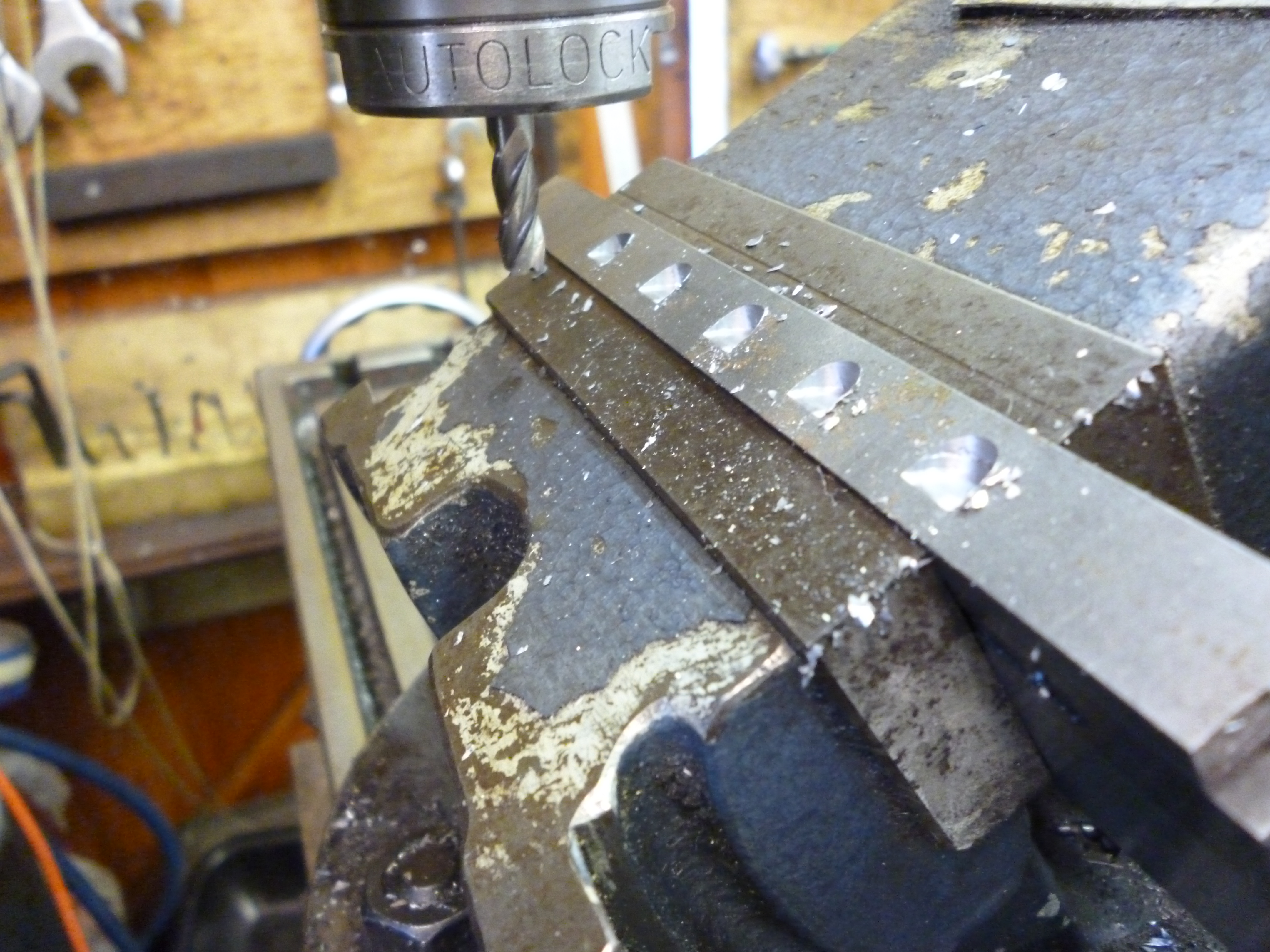
As much metal as possible is removed using a large endmill. This is marked “X” and “Y”. This is done to minimise the amount of cutting that has to be done with the dovetail cutter. Notice that some metal is left so the dovetail cutter not only cuts the angled bit but also makes the final cut of the horizontal surfaces that touch.
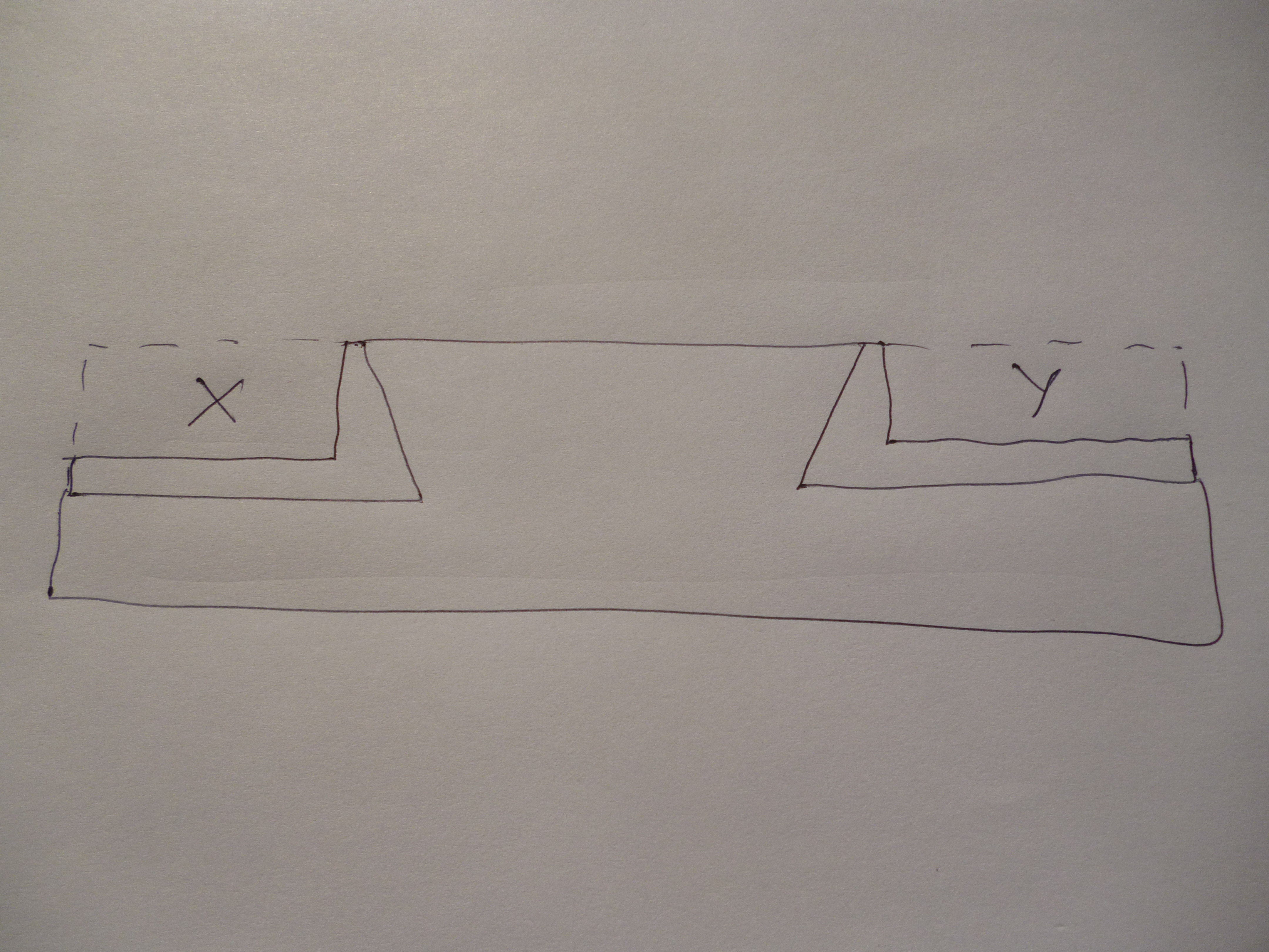
Area to be roughed out with an endmill
The side bits between B’ and A’ are cut with a dovetail cutter, as are C’ and D’. It is essential that the heights of surfaces A’ and D’ are the same. These are all of and yet the only surfaces that make contact with the female part.
The height of the bottom of the dovetail is set to be 0.5mm above the desired height of A’ and D’. The cut starts from the side and as many passes are cut till the required depth, horizontally, is reached.
This is done to one side then to the other. At this point almost all the metal that needs to be removed has been removed. All that is left is a final finishing cut. This must be done with the dovetail cutter at exactly the same height for both sides. The whole point of this is to ensure that surfaces A’ and D’ are exactly the same height. It is also desirable to get the best possible finish on the surfaces on the male part that will rub with surfaces on the female part. That is, A’, B’, C’ and D’.
To be absolutely sure of straightness and parallelism, the final cuts should be done with the y axis locked.
The dovetail when assembled, with the gib, will have B and B’ touching or, D and D’ touching.
Whilst the male part is still mounted it is worth using an endmill to just take off the sharp edges. Unless the dovetail cutter cuts perfect corners when milling the female part these corners will clash. Furthermore these corners can easily be damaged and this will also affect the fit. These are marked “X” and “Y” on the previous drawing. Cutting the opposite corners with, for example, a slitting saw unnecessarily difficult..
The surface of the middle never touches anything so it does not have to be machined at all. Both sides can be machined like this if the workpiece is held on parallels. But there are reasons for not machining the sides at this point – see later.

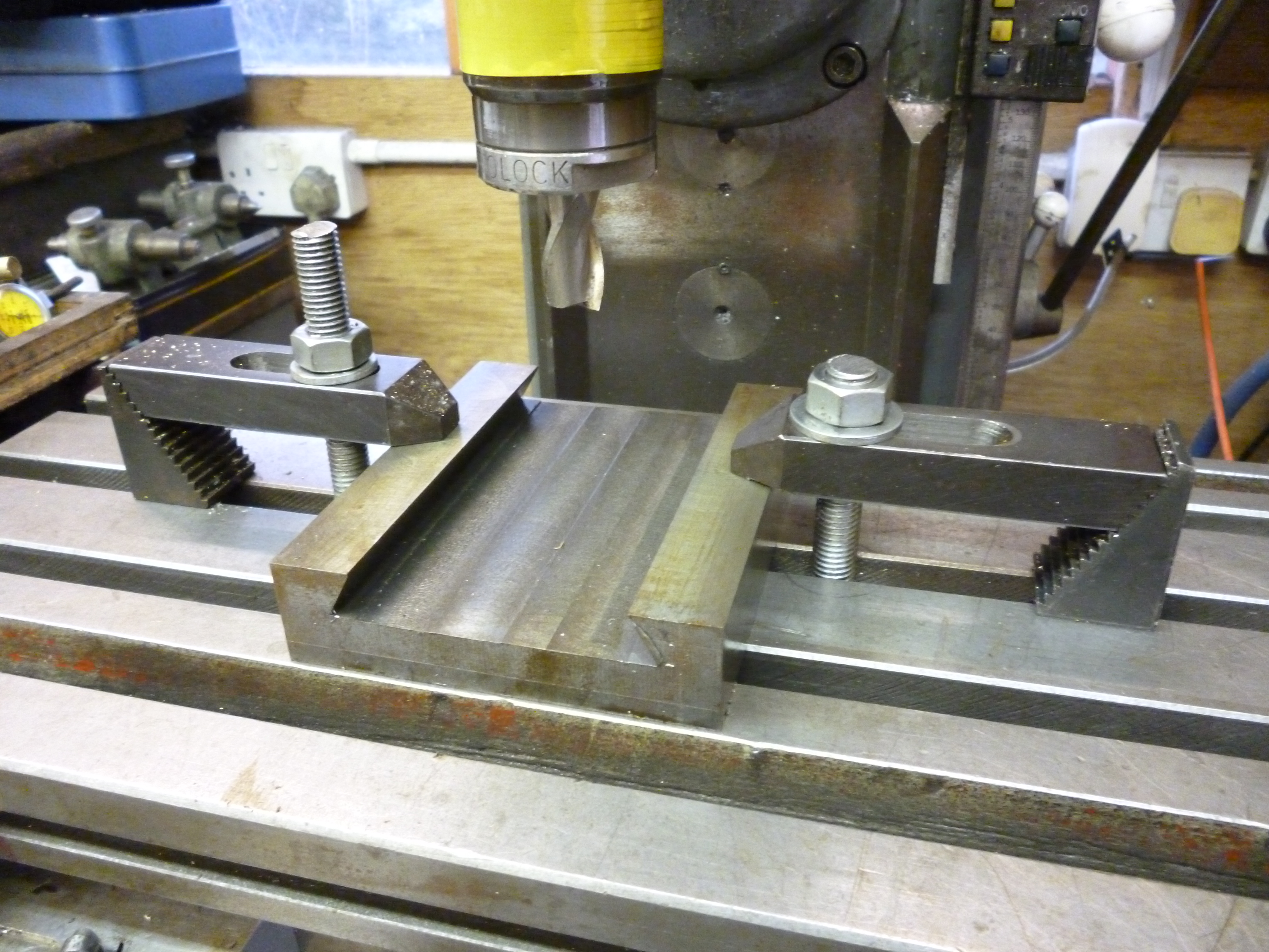
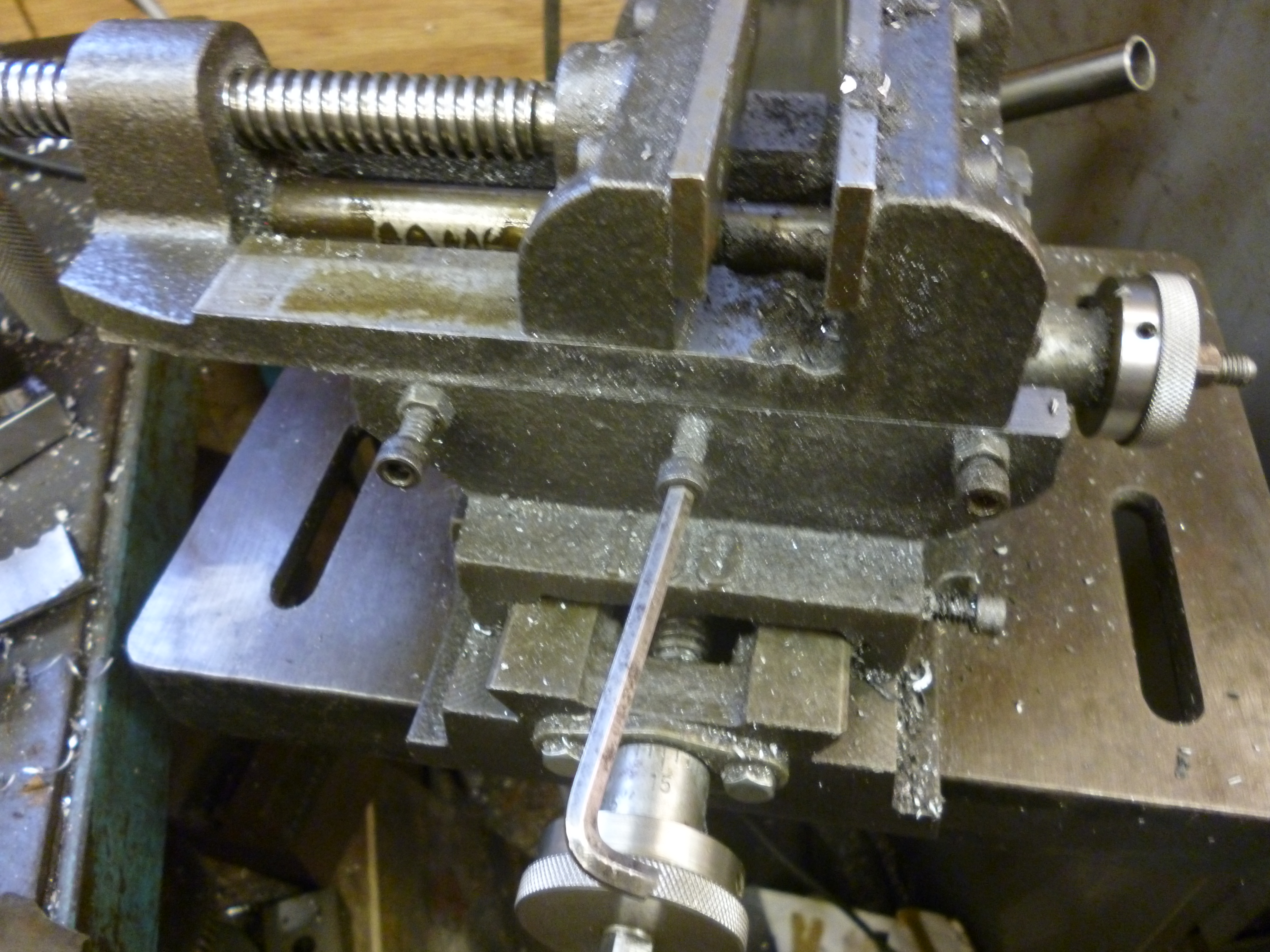
Machining the male part – 498
If the workpiece is clamped with clamps that extend beyond the workpiece as above it might be difficult to do the last cut on one side and then bring the cutter round for the last cut on the other side. This problem can be avoided by using side clamps that clamp the workpiece at the bottom.
Dovetail – type 1 – parallel gib – Making the female part
The female part appears to need all of its surfaces machining. However most of the recessed surface does not touch the male part of the dovetail. So its accuracy relative to the other surfaces is unimportant. So it is possible to machine out most of the dovetail with an endmill.
It is possible to machine this with the sides of the female part clamped as shown.
Roughing out the female part – 496
Notice that it is this way round because it is too wide to clamp the other way round on this milling table. It might seem impossible to do this as surfaces A and D are not exposed for machining. It would be better to have it the other way round if suitable clamps were available. These would be low side clamps but clamped on the ends of the workpiece.
Having done this it can then be clamped holding just the surface in the roughed out part.
final machining of female part
It is now the other way round. It is now possible to machine all the other surfaces in one setting with a dovetail cutter.
The back surface, “Z”, must be flat so that when it is clamped it will not be distorted.
The only crucial surfaces are A and D which must be in the same plane and B and C. The depth of the recess must be at least as deep as height on the male part. The gap between the male and female parts, when fitted together, must be large enough for the gib.
On the female component there are also two sharp, external corners, X and Y. Use an endmill as before to just take the edge off.

Female part of the dovetail – 34
Other ways of doing this
It is also possible to machine both the male and female parts of a dovetail by holding each part at either end with side clamps. In both cases this means the entire top surfaces and side surfaces can be machined in one setting of the workpiece.
If it was not so wide it could be held in a vice and all machined in one go.
The sides
It is a good idea to machine the sides of the dovetail at the same setting as machining the dovetail parts. These can be machined so the dovetail is in the right place on the finished part.
This is essential if the part being made has a female dovetail in it on one side and another female part at right angles to the first on the other side. The side provides a reference surface.
Dovetail – type 1 – making the parallel gib
Adjustment of dovetails with parallel gibs
Most dovetails have to be such that there is no play between the male and female parts. This usually means that the gap between them has to be adjustable. This can be done in one of three ways.
On most dovetails one part is usually longer than the other. Since the adjustment has to be on the outside of the wider part, the adjustment is on the female part so the inside, that is the male part, is, usually, the longer part.
In this the gib is just a parallel strip that fits in the gap between the male and female part. There are screws that can be adjusted from the outside of the female part that push the gib against the male part.
The gib should fit the gap fairly tightly so minimising the “floating” length of the screws holding it.
Ideally these screws should exert an even pressure on the male part. This is done by making the gib thick enough and by making the spacings of the screws holding it small enough so they can apply an even pressure to the male part of the dovetail along the whole length of the female part.
The screws have to “fit” the gib. Firstly so it cannot move laterally and, secondly, so the screw applies an even pressure even as the gib moves slightly relative to the screws. This is often done by using a dimple where the screw touches the gib. This is often made by drilling it with an ordinary drill. But it is better to mill a flat that will be at right angles to the adjusting screw. These screws need to lock nuts to hold them in place after they have been properly adjusted.
Clearly the thickness of the jib should be thick enough to take such flats. There is a pay off between the thickness of the strip and the spacing of the screws used to press it against the male part. This also means that it is important to use all the space in the gap as far as possible. This means the gib should have a trapezoidal shape.
The cross section of this gib is the same from one end to the other.
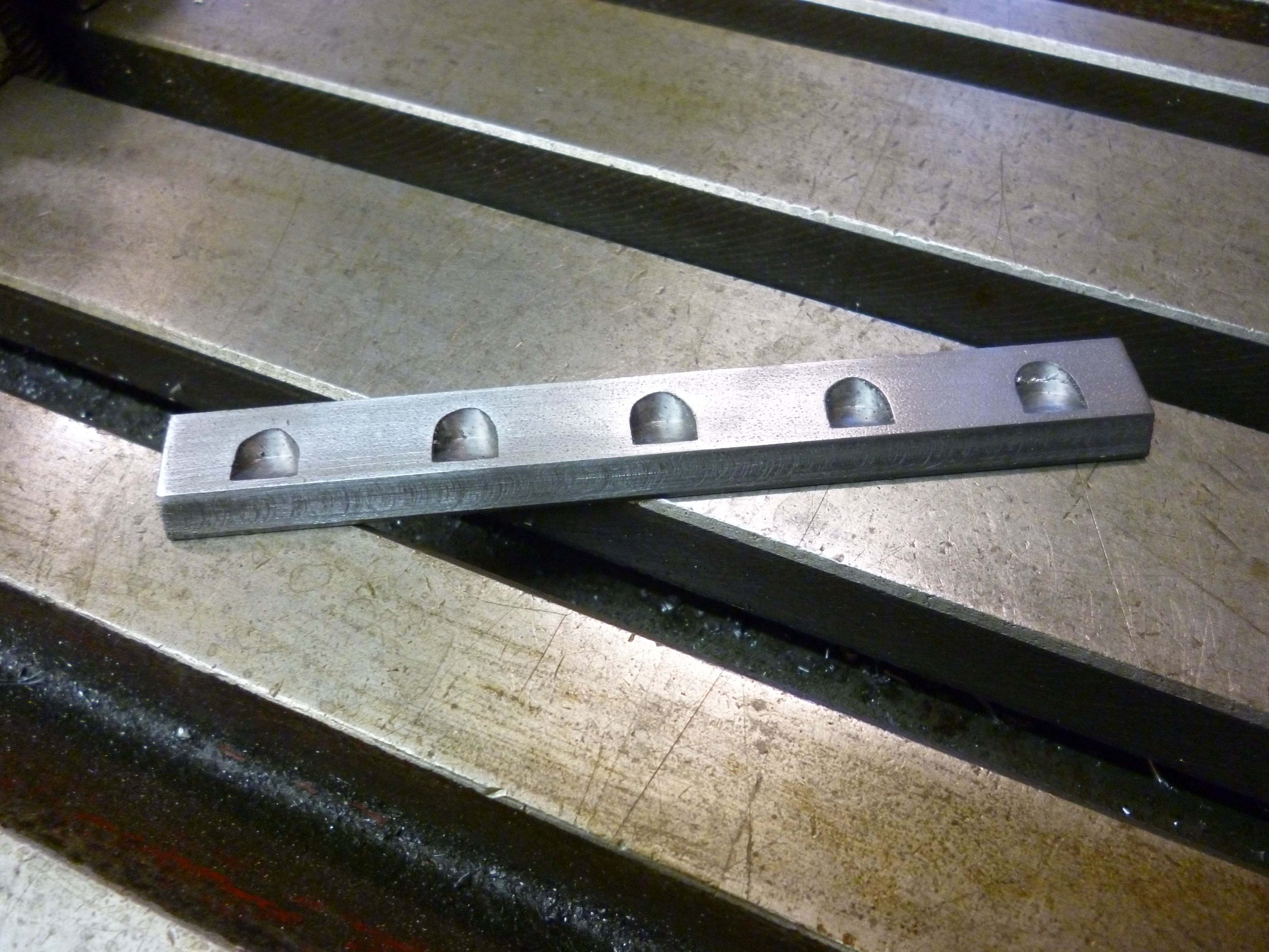
finished gib –
Making a parallel gib using a tilting vice
On smallish dovetails the height of the gib might only be about 3mm thick. In order to make the best use of this space the gib should be milled so, when it is fitted, the top and bottom surfaces are horizontal.
Before doing this there is another job that needs to be done. It is usual to drill shallow holes in the gib so that the adjustment screws will just sit in these. This stops the strip from sliding as the two parts of the dovetail move relative to each other. The problem with this is that one is never sure when adjusting the dovetail whether the screws are in optimal contact with the strip. The best way of doing this is to mill a flat surface with a slot drill.
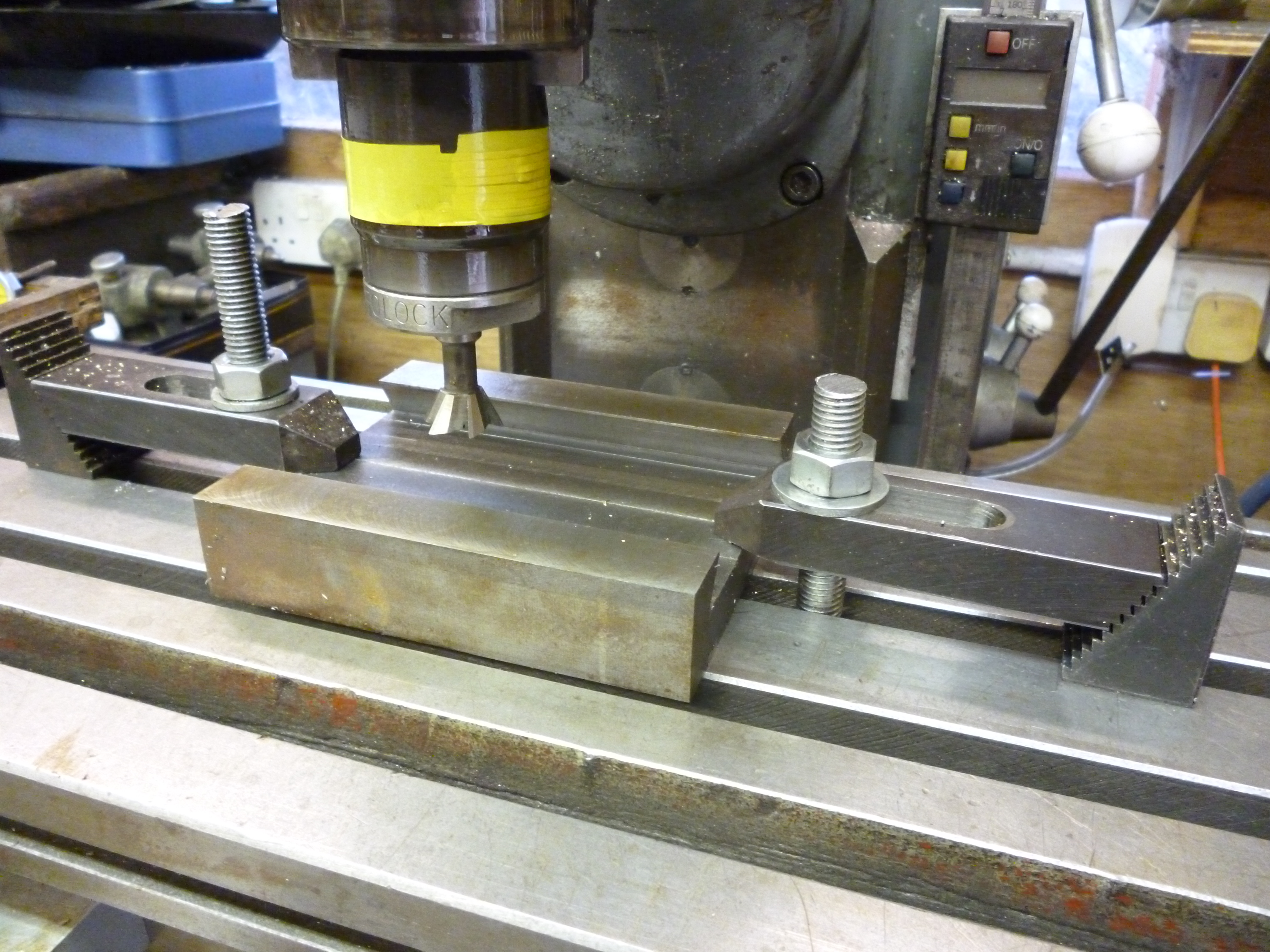
Milling the flats on the gib – 421
All of this can be done using a tilting vice. It is essential to mill the flats first because it is still easy to hold the gib horizontally in the vice, then till the vice to 30º, and mill the flats. However, with the vice at the same angle the gib is held flat in the vice and one edge milled. The gib is then turned over and the other edge is milled

Milling one edge of the gib 422
The same is done the other way round for the other edge.

423 – Finished gib
(These examples were done on a swivel and tilt vice but this could have be done just as well on a tilting only vice.)
An alternative way to make a parallel gib
This is an example of where one part of the job can be used as a fixture to hold another part. If part of the dovetail is clamped to the milling table then the gib can be held at the required angle by holding in one side of the dovetail by mean of a round rod. The female part of the dovetail, gib material and rod are clamped together using toolmaker’s clamps. It is now possible to mill the top of the gib to the right (ie correct) angle. Saw off the bits that were not milled. Turn the gib over and machine the other edge.
Fig. – holding material for gib
This does not compare with using a tilting vice.
With a parallel gib the surfaces of the female part do not have to be perfectly parallel. Any error can be compensated for by the gib. But making them parallel is so easy, if done properly, the “advantage” in not doing so is worthless.
Locking a dovetail with a parallel gib
It is often useful to be able to lock a dovetail in a particular position. In this case it can easily be done by simply replacing one of the adjusting screws with a cap screw that can be tightened with an Allen key to lock the slide.
Locking a parallel gib 730
The screws used for adjusting the gib have lock nuts. The screw for locking does not. However many screws are used for adjusting the gib only one is needed to lock the slide.

Thank you John, for this very good write-up. I have no milling machine and so have hand filed a strip of Starrett 3/32″ bar stock to hopefully make a new gib for my 1920 “South Bend style” lathe (bought for $50). Somehow someone bent the gib on the compound of this lathe and so I am attempting to make a replacement. I will attempt to make a crude copy of your “parallel gib” slot to improve the 4 dimples I drilled to accept the noses of the adjustment screws.
Here’s my question… I have read that many lathes use ‘locating dowels’ at each end of the gib to keep it from moving around as the compound is moved. It is easy to drill holes through the casting but when the drill hits the gib (sandwiched by tightened adjustment screws) it will hit at a 30 degree angle. I doubt it will cut into the gib at that angle and probably will just twist and make the casting hole oval. Perhaps I could use my Dremel with a diamond ball tip…. do you think that would work? I am concerned a 20k rpm Dremel bit might be unhappy in a hole and bind up… Advice please? Cheers, Pavel in Canada.
I have seen the use of a small pin to keep the gib in place. If you make recesses for the screws this is totally unnecessary. If you were to drill a hole through the dovetail and gib the problem would not be where the two parts touched it would be where the drill left the material where the material was at an angle. This is quite likely to cause the drill to break if it is small.
john f
Thanks for answering John… Yes, I suspect the drill will break or “wander” when applied at such an acute angle – even if applied very gently. That’s why i thought a Dremel bit (they come with diamond tips of various shapes) might be better to at least start a dimple. For some reason, I have not been able to adjust the compound dovetail + gib – if it is set so there is little play at one end, it is too tight at the other end of its travel. I’ve simply kept the compound (with toolpost) in the middle of its travel and adjusted the gib for that position. Perhaps that is all I can expect from such an old and worn machine. Cheers, Pavel.
I dont think using a diamond coated bit will help. If the male part of the dovetail is not parallel the gib cannot compensate for this. You might be able to improve it by marking it with blue, seeing where the high spots are, and filing them down with a needle file.
john f
Hi
I want to ask you the dovetail is iron cast or steel?
Usually the material is cast iron. These would be castings or from lumps of cast iron. Cast iron on cast iron slides quite nicely with a bit of oil in between