go to the page above this one drilling – techniques
Drilling holes in a circle
It is a common requirement to be able to drill holes that are in a circle. This would occur on a flat surface such as a cylinder cover. But this is just one case. It is also possible for the holes to be on the outside of a round surface. Then, of course, there is a surface that is in between these two cases, for example, on a conical surface or spherical surface..
There are two basic ways that can be used to determine where the holes are going to be drilled. The first is by knowing the position of each hole in terms of its x and y coordinates. These can be found by using tables showing the coordinates for a “standard” circle with a certain number of holes. These can be found in data books such as the “Zeus” one. This is not as easy as it looks. In particular the coordinates need to be scaled for the size of the circle and allowance has to be made for the orientation of the circle and the position of the center of the circle to some reference point is needed.
An alternative way of doing this is to use a CAD package to produce a drawing with all the holes on it. The Cad package is used to find the actual coordinates for each hole relative to some reference point on the drawing.
In these cases the coordinates of each hole is its position in both the x and y directions.
This can best be done on a milling machine, especially if it is fitted with DRO’s
Using a rotary table in the horizontal position
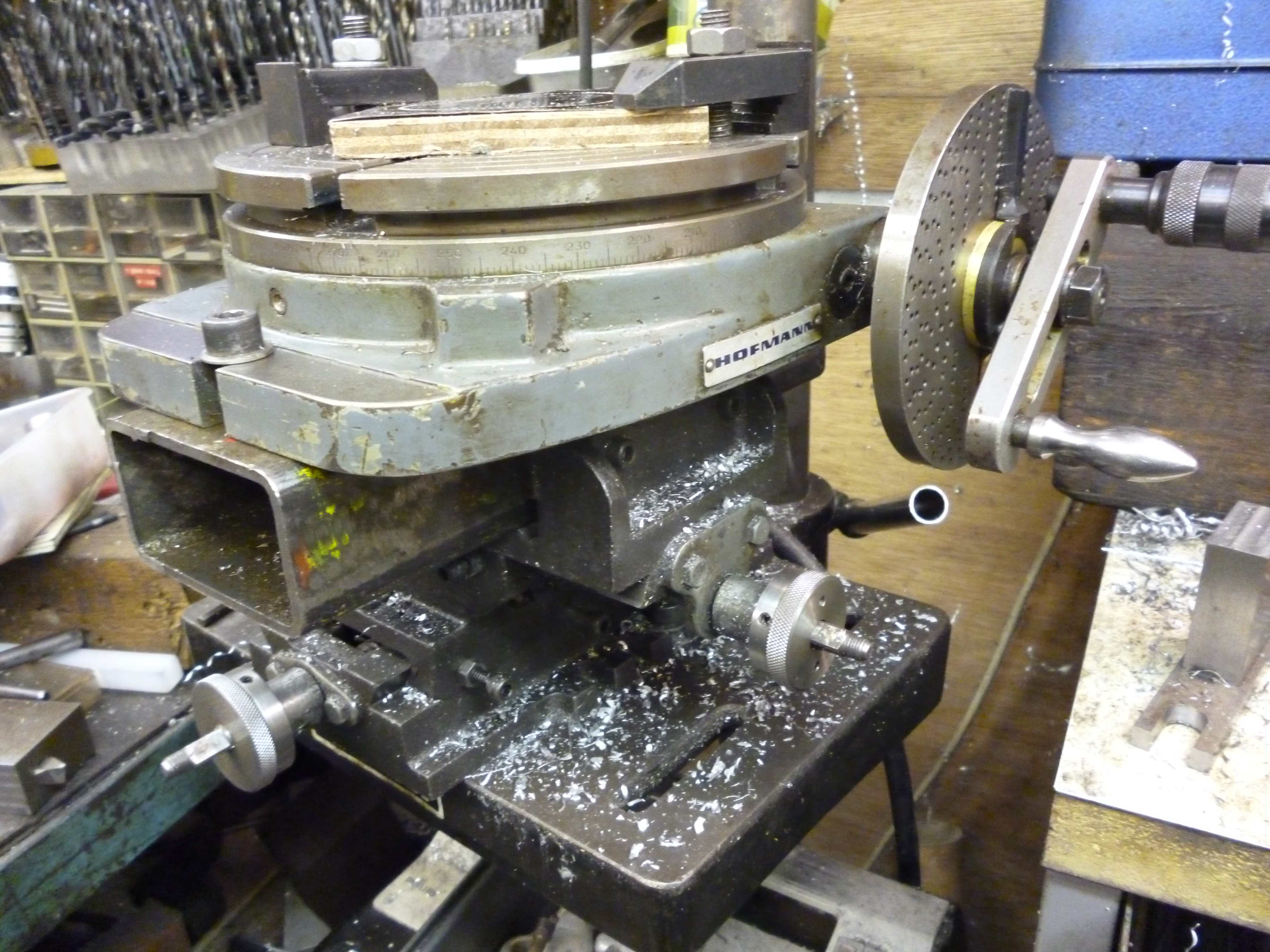
The easiest way of making a series of holes in a circle is by using a rotary table. The reason for this is that, functionally, the position of the holes is not defined by x and y coordinates but by to radius of the circle and the angles between the holes. Very often when there is a circle of holes, the holes will be spaced at equal angles from each other.
The beauty of using the rotary table is that it allows us to set the position of the workpiece by an angle from the previous hole.
Again, with this method, it is best done on a milling machine.
Of course a rotary table could be used on the pillar drill but it is much easier on the milling machine.
fig using the milling machine
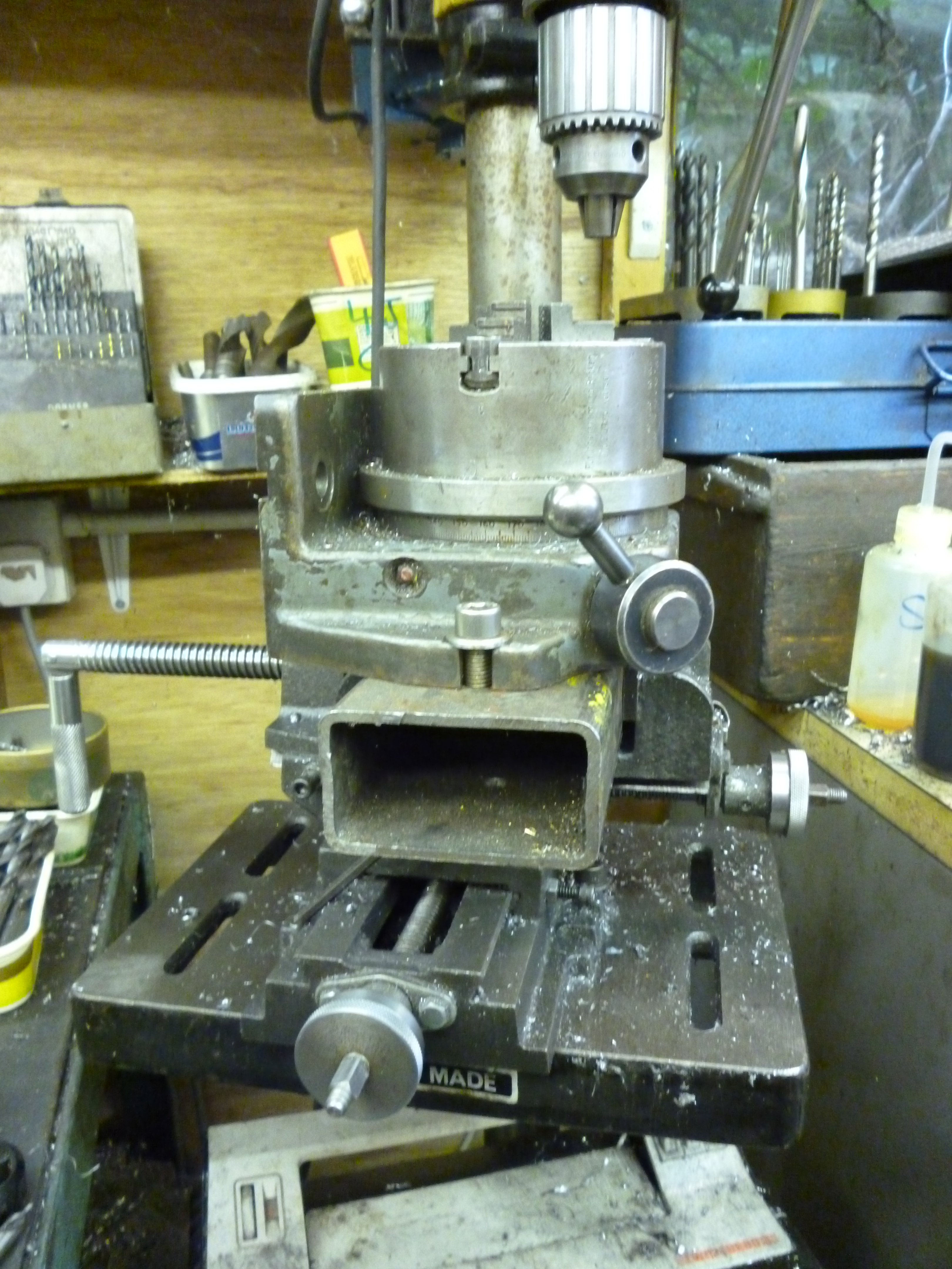
4331 rotary table on pillar drill
fig using a rotary table on a pillar drill
3109 rotary table on pillar drill
fig using an indexing chuck on a pillar drill
This is because it is easier to move the rotary table about in the x and y directions accurately. This is necessary for centering the rotary table and then for setting the radius of the pitch circle.
Drilling holes on a flat surface
Drilling holes round the outside of a round workpiece
Where holes have to be drilled on the outside of a round surface a completely different approach is needed. Essentially the workpiece has to be held horizontally and then it is rotated around a horizontal axis. An example of this would be holes round the side of a smoke box. There are two ways of doing this. The workpiece could be held using a dividing head. Or the workpiece could be held using a rotating table fixed vertically.In this case, since the workpieces are usually round, the workpiece is held using a chuck fitted to the rotary table.
On this website there are many examples of this. The only difference here is that the “cutter” here is a drill bit probably held in a drill chuck fitted to the vertical spindle.
fig drilling holes round a workpiece using a dividing head
fig drilling holes round a workpiece using a rotary table fitted with a chuck
