go to the home page
go to the page above this one
Making a spur gear – step by step example
This is an example of making a spur gear. It is done step by step.
The gear to be made has 35 teeth. The size of the teeth is 1 MOD. For a 1 mod gear the pitch circle diameter, pcd is the number of teeth in mm. The outside diameter, od is:
OD = pcd + mod * 2
= 37mm
for this example the gear is made of steel 1/4 inch thick.

Piece of scrap steel sheet 1010
A square was marked out that was a bit bigger than was needed for a 37mm disk.
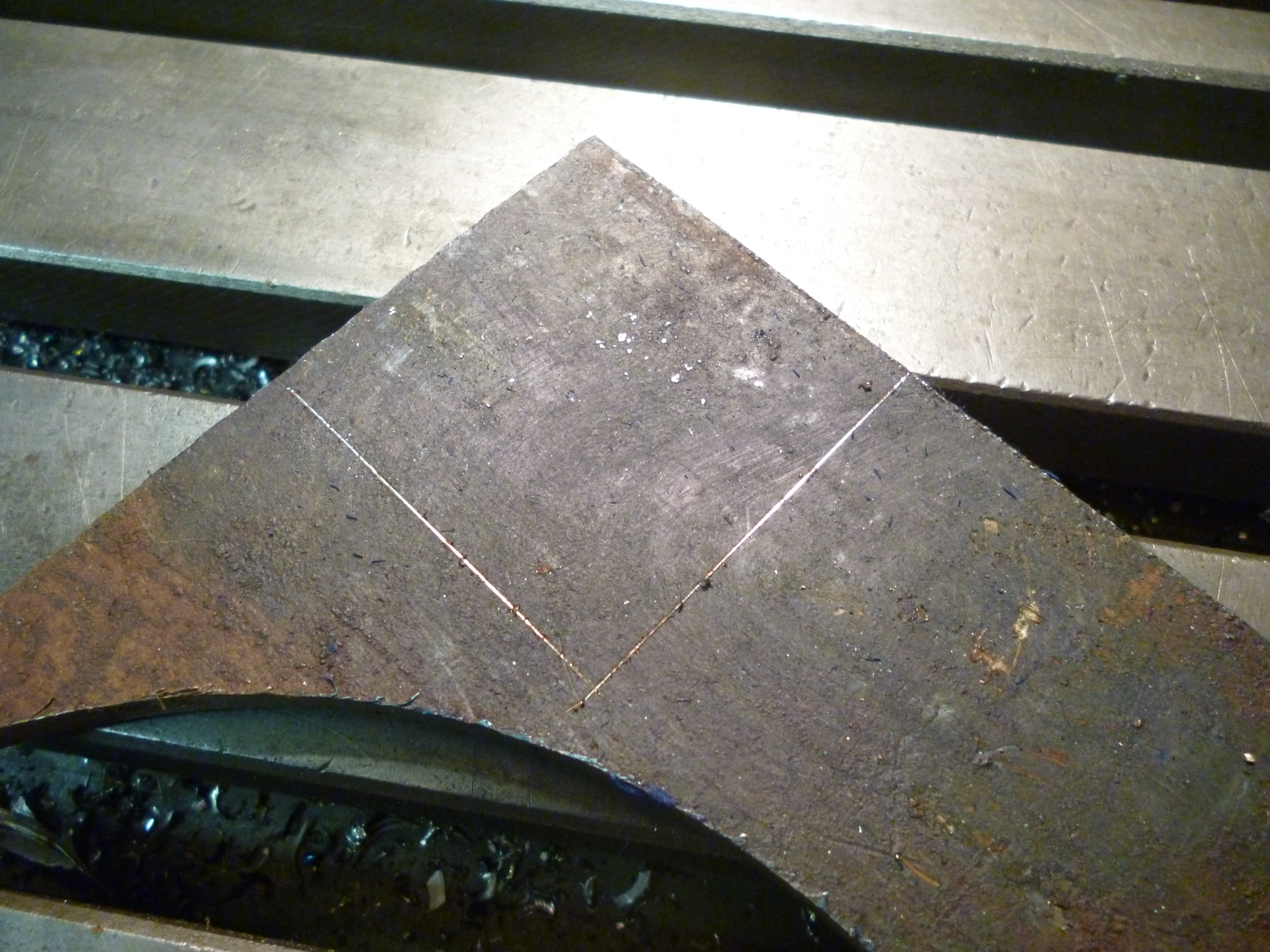
required material marked out 1011
This piece was chain drilled.

Piece chain drilled and sawn out 1012
It is important that the burrs made by drilling are filed off so this piece will lie flat in the chuck.
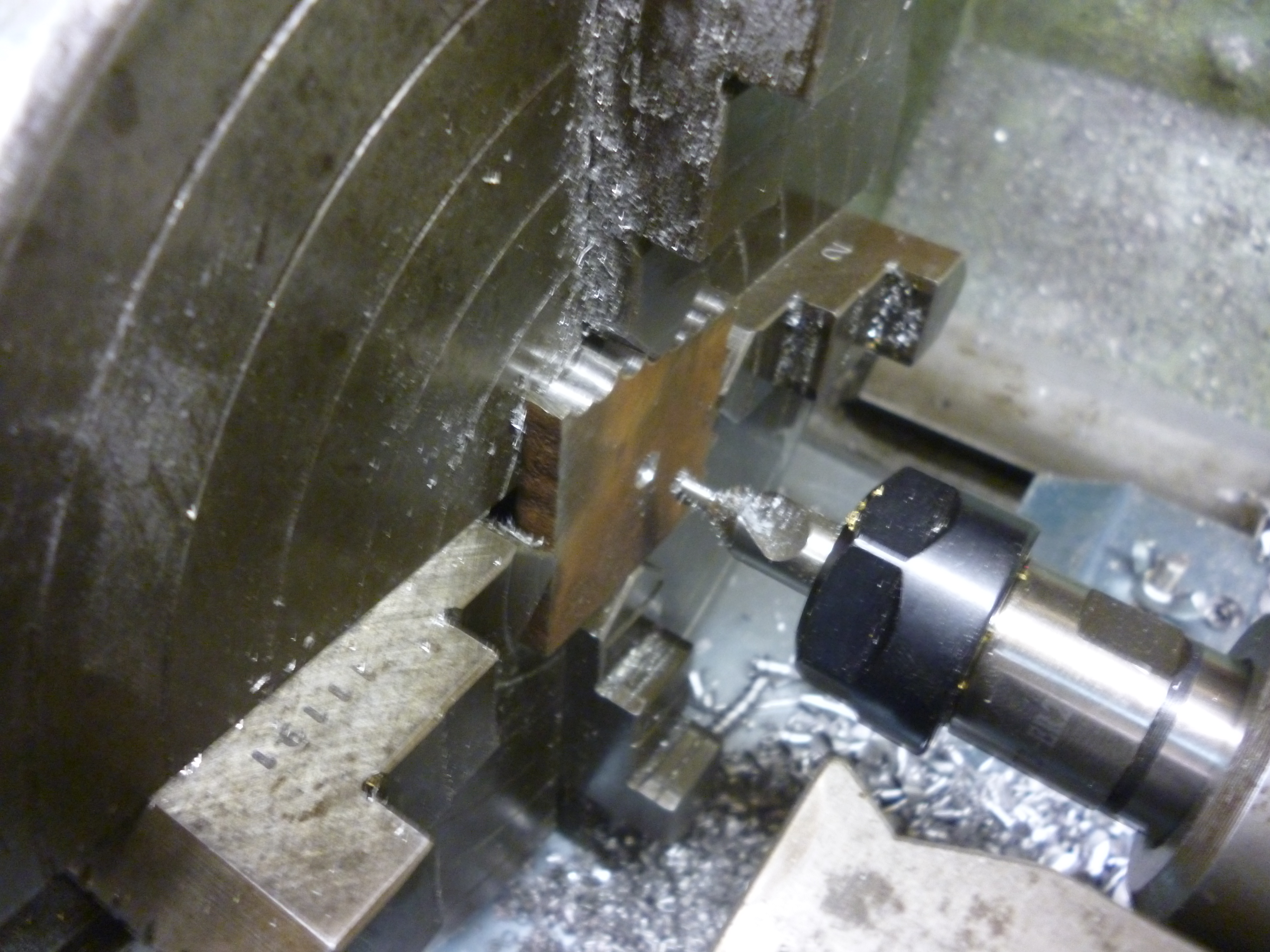
Center drilling
The workpiece is not held on the surfaces of the jaws as it would not be possible to drill/ream all the way through it. It is held flat against the body of the chuck.

1014 piece drilled with small drill
It is then drilled with the drill required for the reamer.

1015 piece drilled with reaming drill
It is then reamer to fit the arbor.
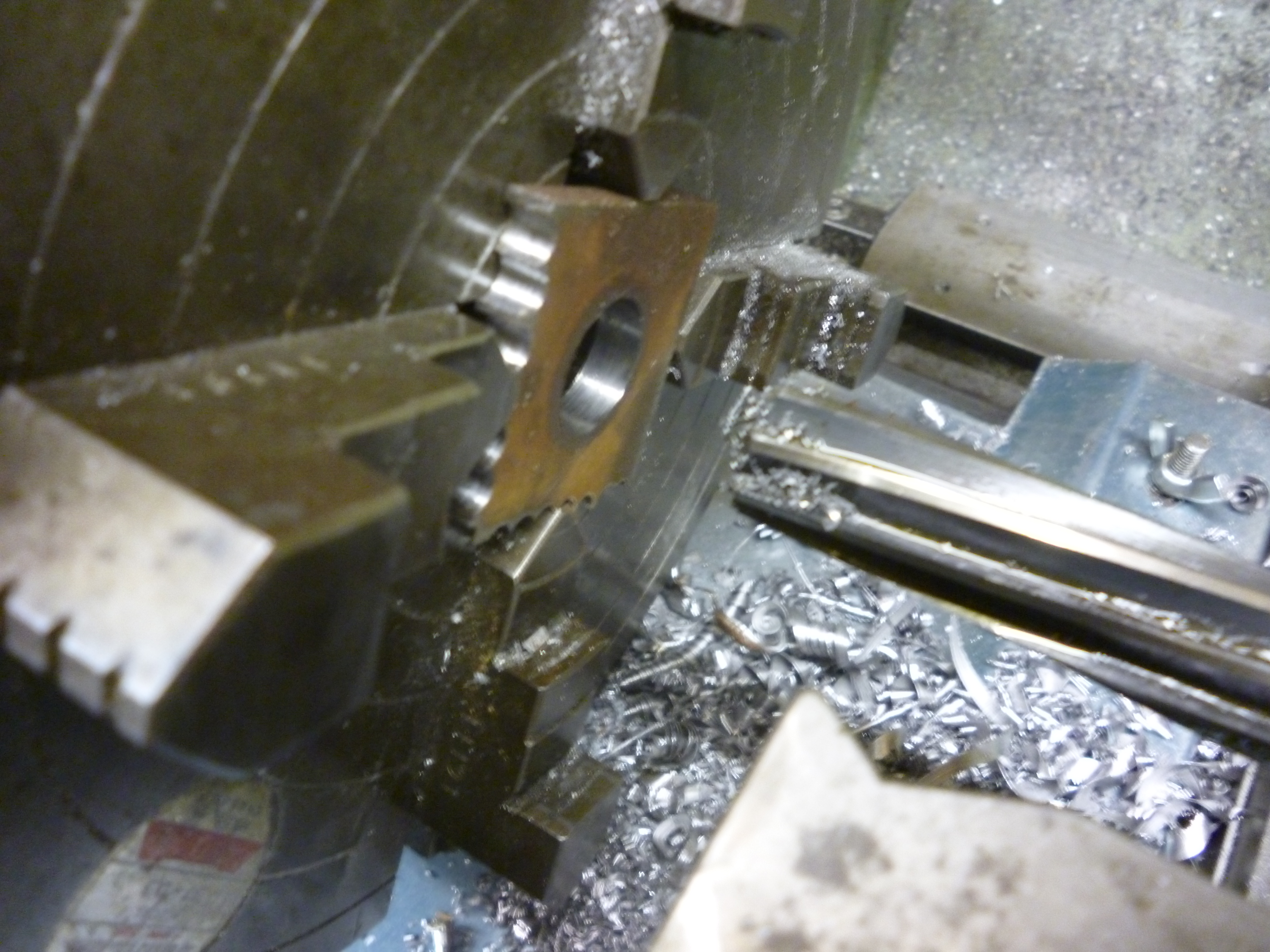
1016 piece reamed
The workpiece is removed from the chuck. The arbor is fitted to the chuck.
The arbor is centered in the chuck. This is done roughly by using the tip of a cutting tool to mark the edge.
1017 Arbor roughly lined up using tip of cutter
The arbor is then centered as accurately as possible using a DTI.

1018 arbor centered with dti
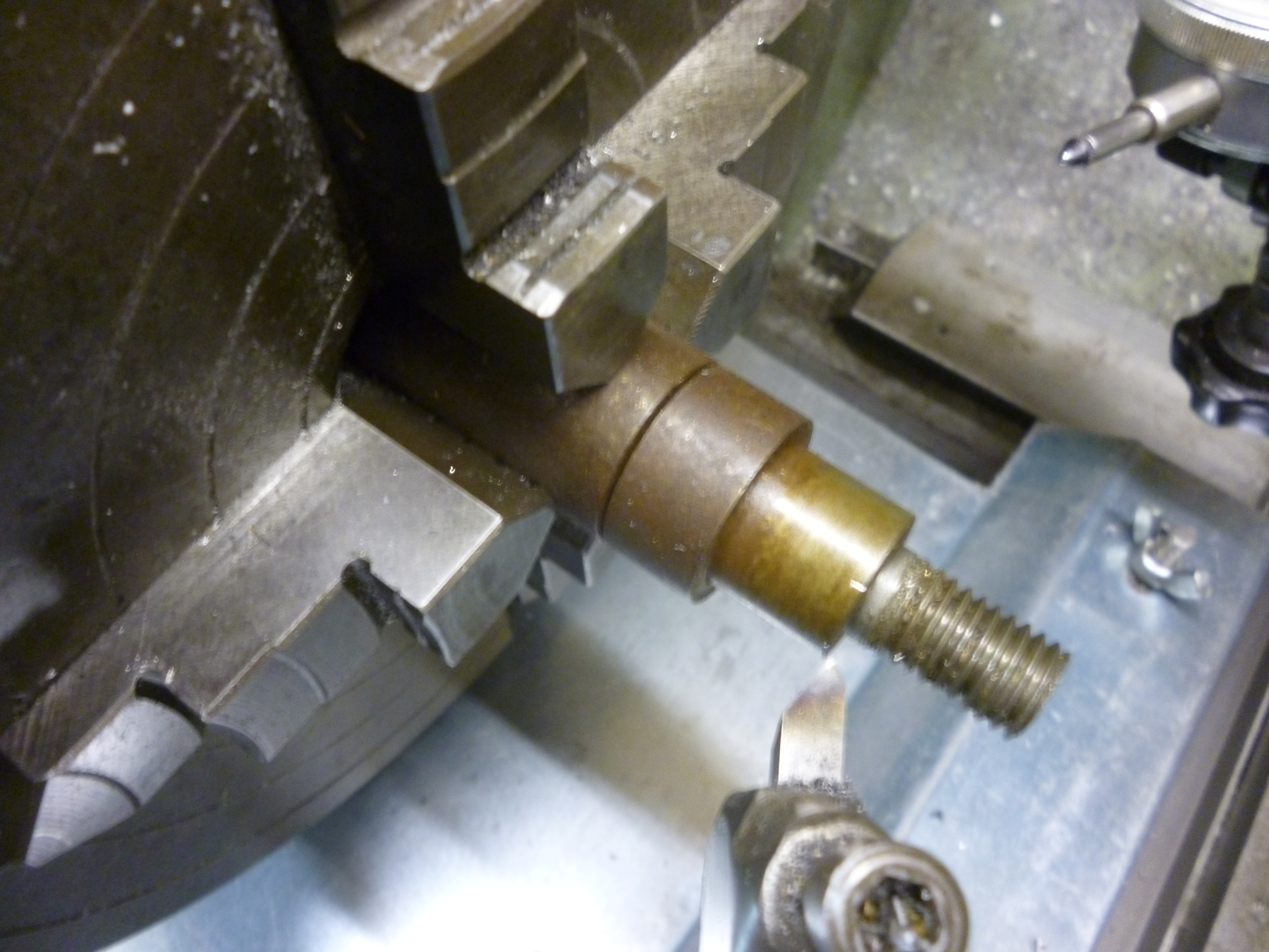
The workpiece is then mounted on the arbor and done up tightly. It is turned to the required diameter.
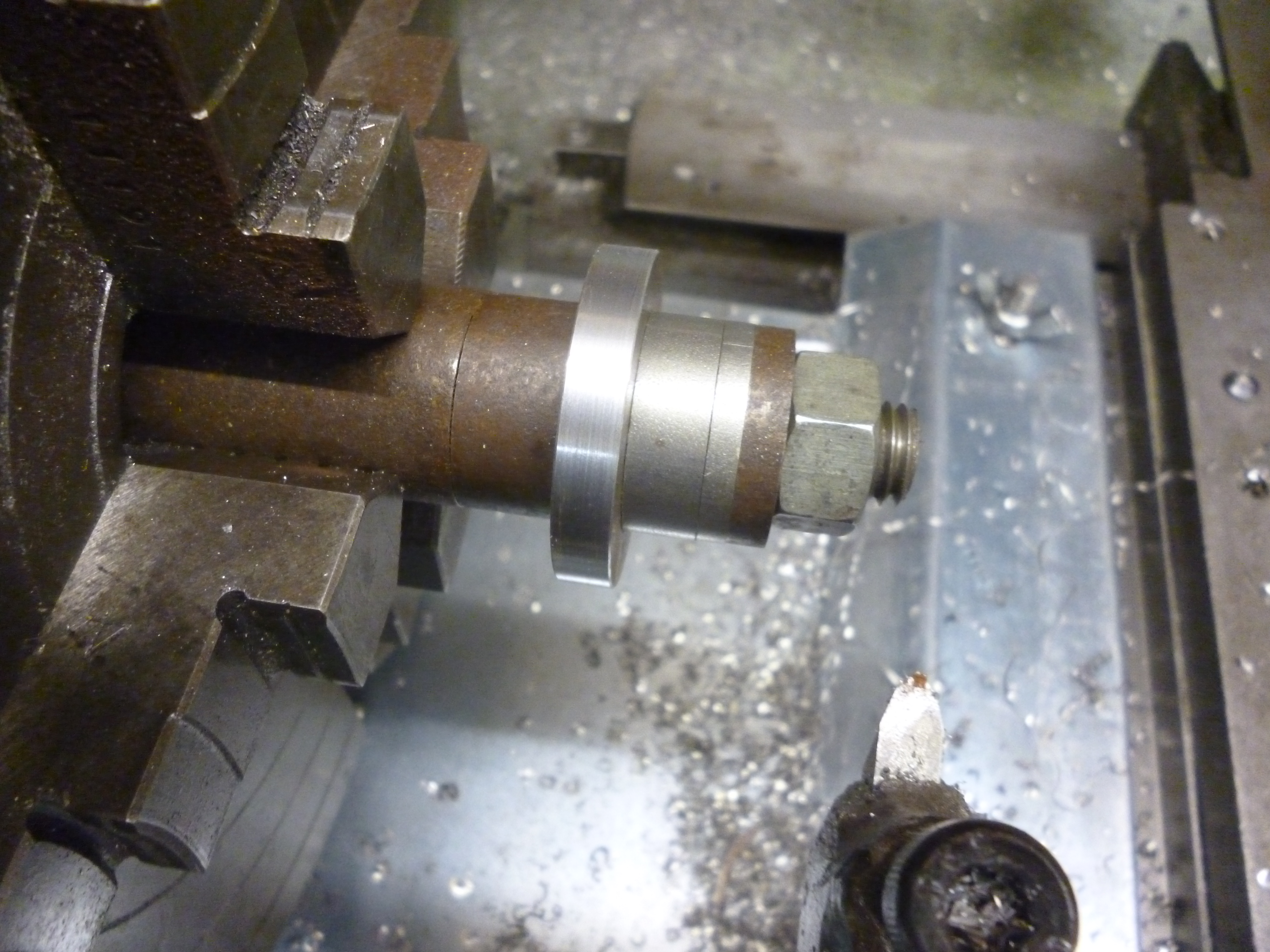
1019 arbor fitted with workpiece and turned to size
The arbor is removed from the chuck on the lathe. It is then fitted in the chuck on the dividing head. The tailstock is pushed up against it a bolted in place.

1021 arbor fitted to dividing head and tailstock (1)
The cutter used has to be for 1 mod gears, it has to be the one covering the range of teeth which includes 35. it has to be for the required pressure angle. It probably has the required depth of cut stamped on it. In this case this was 0.087 (inches!!!).
The cutter has to be exactly at the center height of the gear..
This can be done as follows
D = diameter of arbor measured with a micrometer
X = width of cutter mesured with a micrometer
H1 = height of top of arbor above milling table measured with height gauge
H2 = height of top of cutter above milling table measured with height gauge
H2 = H1 – 0.5* D + 0.5 * X
The cutter can then be set along the y axis.
The cutter is turned till the tip of a tooth is along the y axis from the center of the stub axle. (Ie turned till the tip of it tooth is sticking out as far as possible towards the workpiece.)
It is moved towards the workpiece till it just touches. This can easily be tested using a piece of cigarette paper. The milling table is set to zero on the y axis. The workpiece is move to the side of the cutter and the cutter is moved in by 0.085inches. A ll the cutting is done at this depth so the table can be locked in the y direction.
In this case the dividing head is holding the arbor using a three jaw chuck. These are never very accurate. The error will be the same regardless of the size of the gear being cut. On gears with large teeth this might not be so bad but on those with small teeth this can be serious. The arbor should be held between centers or by using a dividing head with a four jaw chuck.
Setting the dividing head
The dividing head has a worm/wormwheel ration of 40 to 1. But any turn can be divided by any factor that suits us. In this case the circle needs to be divided by 35. The factors of 35 are 5 and 7. The 40 already contains the factor 5 so all we need is a 7. Looking at the dividing plate one ring of holes contains the factor 7. That is the ring with 21 holes.

1030 dividing plate showing first holes of each ring
If we pick this ring then if we turn the handle 40 times ie 360 degrees, then the pin will pass 40 * 21 spaces on the dividing plate. This is 840. But we want to divide by 35. If we divide 840 by 35 it gives us the number of spaces that must be passed for each tooth. This is 24 spaces. But we are on a ring with only 21 spaces. This means the pin has to make one complete revolution plus an extra 3 spaces.
At the start of machining the pin must be in the first hole and the sector arms are set to include three spaces – spaces – not holes.

1023 Dividing head at start of first tooth
The cutter is turned on. The table is moved, in this case, from right to left. One “tooth” is cut”. The cutter is stopped and the table moved back. Make sure the workpiece is going to be clear of the cutter as it is turned.
After each tooth is cut the pin is rotated by one whole circle and the three more spaces as defined by the right hand sector arm. The sector arm is then moved so that the left arm is touching the left side of the pin.

1024 pin in position for second tooth
The sector arms are then moved round.
This is repeated till all of the teeth have been cut.
If after the last tooth has been cut, the workpiece is rotated by the same amount again the the cutter should arrived at the very first tooth cutter and should fit this perfectly.
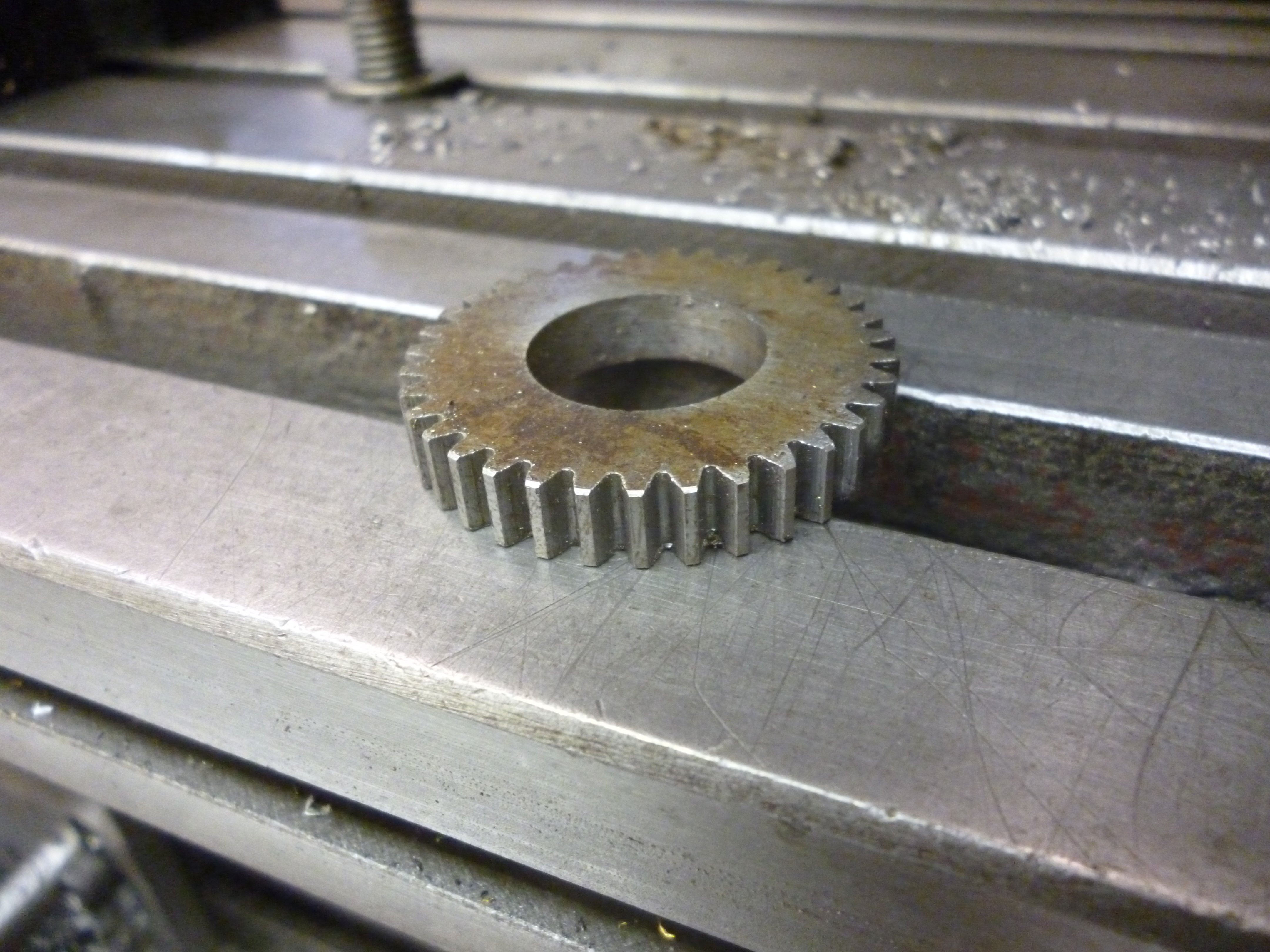
1029 the finished gear

hi john.
Thanks’ for this excellent lesson in cutting spur gears. There must be an infinite number of cutters for various different sizes and ratios of gear trains. My mill is a horizontal shaft 1″ diameter. Please where would I obtain cutters.
Regards
John
If you find the page “making spur gears using a dividing head there is a piece on “buying gear cutters”. This is about preferred sizes. I buy almost all my stuff on ebay. A gear cutter would cost about £5-£15.
john f
Can i ask something, when used milling machine, how to set center point for cutting spur gear?,
Very good point.
You should know the center height of the dividing head.
The center of the cutter has to be at this height
You can use a height gauge to measure the height of the top of the cutter
You can also use it to measure the height of the underneath of the cutter see my page on height gauges I think.
You need to calibrate the top of the probe on the height gauge. I think mine is 10.86mm
I am just going out so I cant check it now
let me know if you cant find it.