Back to the home page
Back to the previous page
End rounding – convex
A very common task is to give a bar or tapered component a round end. On pieces of tooling it is often possible to leave a square end but the job looks unfinished. A properly done round end is often essential for a professional finish.
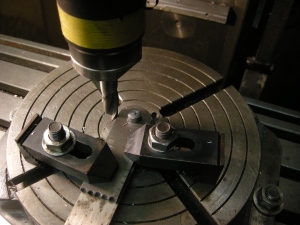
Often there is a hole in the center of the rounded end. In this case, a spigot should be made. One end fits the hole in the rotary table. The other end fits the hole in the workpiece. This defines the position in the x/y directions so only one additional clamp is needed.
- 318 end rounding

If there is no hole then two clamps will be needed.
It is quite easy to set this up “by eye” and the result will often be passable. The problem is always to get the edges of the round section to match the edges of the straight sides.
If the length of the part is less than the distance from the cutter to the column of the machine the intuitive way to set it up is to start with the workpiece pointing towards the user. With longer pieces this will not work.
The setting up arrangement described below covers any case.
To get it perfect is quite involved.
If the width of the workpiece is correct and the center is properly centered then the rotation required can be seen by eye.
End rounding – alignment
1 Center the rotary table with the spindle. xxxx
See Center the rotary table with the spindle xxxx
Leave the spigot etc used for alignment in place
Lock the milling table in the y direction. It is essential that this stays locked throughout the whole operation.
2 Zero the rotary table so the zero is at the fiduciary mark.
3 Set the table to zero
Using the spigot to hold the rotary table in both the x and y directions, rotate the rotary table so the radius to the zero is at right angles to the milling table. Bolt the rotary table to the milling table. Remove the spigot.
4 Fit the workpiece to the milling table
Use a square to set the workpiece so that both sides are the same number of degrees from the fiduciary mark on the rotary table.
5 Move the milling table in the x direction, y remains locked, so that when the workpiece rotates the cutter just cuts the corners. Moves it, in the x direction, so it slowly cuts more and more on each pass.
In initially the cutter will only cut the two corners. But as the job proceeds the workpiece must only rotate between +90 degrees one way and -90 the other way.
If the workpiece does not have a hole in it, it is necessary to use the DTI on an arm or other device to center it with the center of the rotary table. If the side of the bar just touches the side of the cutter on one side, then, without moving the milling table, it should of course just touch on the other side as well. It is very important that this is done as accurately as possible since any error in this will result in the round end not matching up with the sides of the bar.
If the sides of the bar taper at an angle, say, x degrees set the table as before the start and end position will be 0º + xº/2 and 180º – xº/2.
Tip for bodgers
If this can’t be done properly, cut the radius as above but make the bar slightly wider than needed and then use a linisher to get the sides to match the rounded end.
