Milling machine – aligning vices
In all cases of aligning a vice, what is aligned is always the fixed jaw. When this is aligned it stays aligned whereas the moving jaw can change depending on the workpiece.
All of this assumes that the bottom of the space in the vice is parallel to the bottom of the base of the vice. It also assumes that the fixed face of the vice is vertical.
Aligning a plain vice parallel to the milling table
This is probably the most common way of holding a workpiece. If it is used for one job it could well be used for others without being setup up again. In general it is always worth doing this to a reasonable standard.
There have been suggestions for special gadgets for doing this. The problems with these is that they usually work for one particular vice in one particular position. All of the methods here will work where the jaw is at any height relative to the table and also wherever the jaw is across the milling table.
Mew no 182 p40
A Aligning a vice using a DTI
This is the most accurate method but is time consuming.
See tool 9 using a DTI
An example of this can be seen at:
http://www.youtube.com/watch?feature=player_detailpage&v=WR9tLu_nGxg
A2 Aligning a vice using a DTI where the there is table feed
fit the vice to the table at a slight angle. bolt on one side only to the vice will only rotate when hit with a softheaded malet. The DTI just touches one end of the fixed jaw.
The idea is that when the feed is turned on. The dti just touches the jaw. As the table moves the vice is hit soit rotates slightly. Initailly the reading on the dti is large but as the table moves and the vice is rotated the change on the dti gets smaller and smaller till very soon it is zero. At this point the vice is aligned and can be bolted up tightly on both sides.
see youtube
http://www.youtube.com/watch?feature=player_detailpage&v=DdgSxoTmtx0
This does seem to be easier if there is table feed. Notice that the base of the vice seemed to have been aligned quite accurately before attempting to align the top part.
B Using a parallel, angle plate and square method.
This method is usually good enough but is quicker than using a DTI.
See Parallel/angle plate/square
C Using fixed alignment blocks
Since this arrangement is very common it could well be that it is worth having one plain vice fitted with alignment blocks so that it can always be mounted on the milling table and will always be aligned properly.
See method 24 fixed alignment blocks
D Using just one parallel
Fit a long parallel in the jaws. Check by sight against an edge of a T-slot. Though this might be good enough for one job, it will not be good enough for others that might follow it. It is best if this is only used if it is known that it will not be left like this.
Problem 37 Aligning a plain vice at right angles to the milling table
A Aligning using a DTI
Most accurate but the most time consuming
Use Tool 9 use a DTI
B Square, angle plate and square method
This method is usually good enough but is quicker than using a DTI.
See Method 29 Parallel/square/protractor, angle plate, parallel
C Using fixed alignment blocks
This is accurate and quick but only works if the vice can be fitted and is fitted with alignment blocks. Very few vices have slots for fitting alignment blocks for a vice at right angles. It is not often needed like this and this stops it being used parallel to the milling table.
See method 24 Use of fixed alignment blocks
D By sight
Not recommended
See method 23 setting a vice by sight
Problem 41 Aligning a vice at an angle to the milling table
If it necessary to use a vice at an angle to the milling table it is best to use a swivelling vice for reasons explained later.
A swivel vice can be aligned as a plain vice in order to be parallel or at right angles to the milling table in exactly the same way as a plain vice.
A Aligning using a DTI
Cannot be done
B protractor, angle plate and square method
This method is usually good enough and is the only practical method available.
This can be done using a variation of the parallel, angle plate and square method. In this case instead of the parallel a precision protractor is fitted in the jaws of the vice. The other arm is set against one side of the angle plate. The other side of the angle plate is set against the square etc.
See Method 29 Parallel/square/protractor, angle plate, parallel
C Using fixed alignment blocks
Not relevant
D By sight
Not possible
Problem 59 Aligning a tilting vice
A tilting vice can be tilted to an angle using the markings on the vice. The accuracy of these can be limited.
It can be aligned more accurately by fitting a precision protractor in the jaws in a vertical position. The angle will only be correct in the plane at right angles to the jaws of the vice. The protractor must lie in the vertical plane to give an accurate reading. The other arm of the protractor can be tested to be horizontal using a DTI (plunger sort) mounted on the vertical head.

586 aligning a tilting vice
Fig Aligning a tilting vice 586
To do this the jaws of the vice have to lie along the x axis. But this is only so the DTI can run along the blade of the protractor. Once the angle of the tilt has been set it would still be the same if the vice was rotated about the z axis.
Setting the angle on a sine vice
The sine vice works like a sine bar. A stack of slip gauges is put underneath it to set the angle. Since the distance from the point about the vice tilts to the point the slip gauges are in contact with is very accurately set, the angle can be computed.
The length between the axis of rotation and the roller is a fixed length. This is the hypotenuse of a right angle triangle. The height of this triangle is the height of the stack of slip gauges. The relationship between these and the angle ? is:
Sine (?) = opposite (height of the slip gauges)
Hypotenuse (length from axis to roller)
See sine bars and slip gauges
A sine vice might be metric or imperial. Consider the common one made by Jones and Shipman. To be able to make very small angles would require a stack of slip gauges with a smaller height than that of the thinnest slip gauge. The vice is constructed so that with no slip gauges it tilts slightly below the horizontal. To be horizontal it needs a slip gauge of 0.100 inches thick. It is then easy to make up any size bigger than this. So for whatever height is required 0.100in has to be added to this.
Alignment of the swivel, tilt and swivel vice
All three movements of this vice are calibrated. For many purposes these are good enough.
The alignment problem here is the horizontal tilt axis. It is possible for the jaws of the vice to be lined up vertically and horizontally yet not be correct. In the figure the first swivel is at 20° but the top one is at 20° the other way.
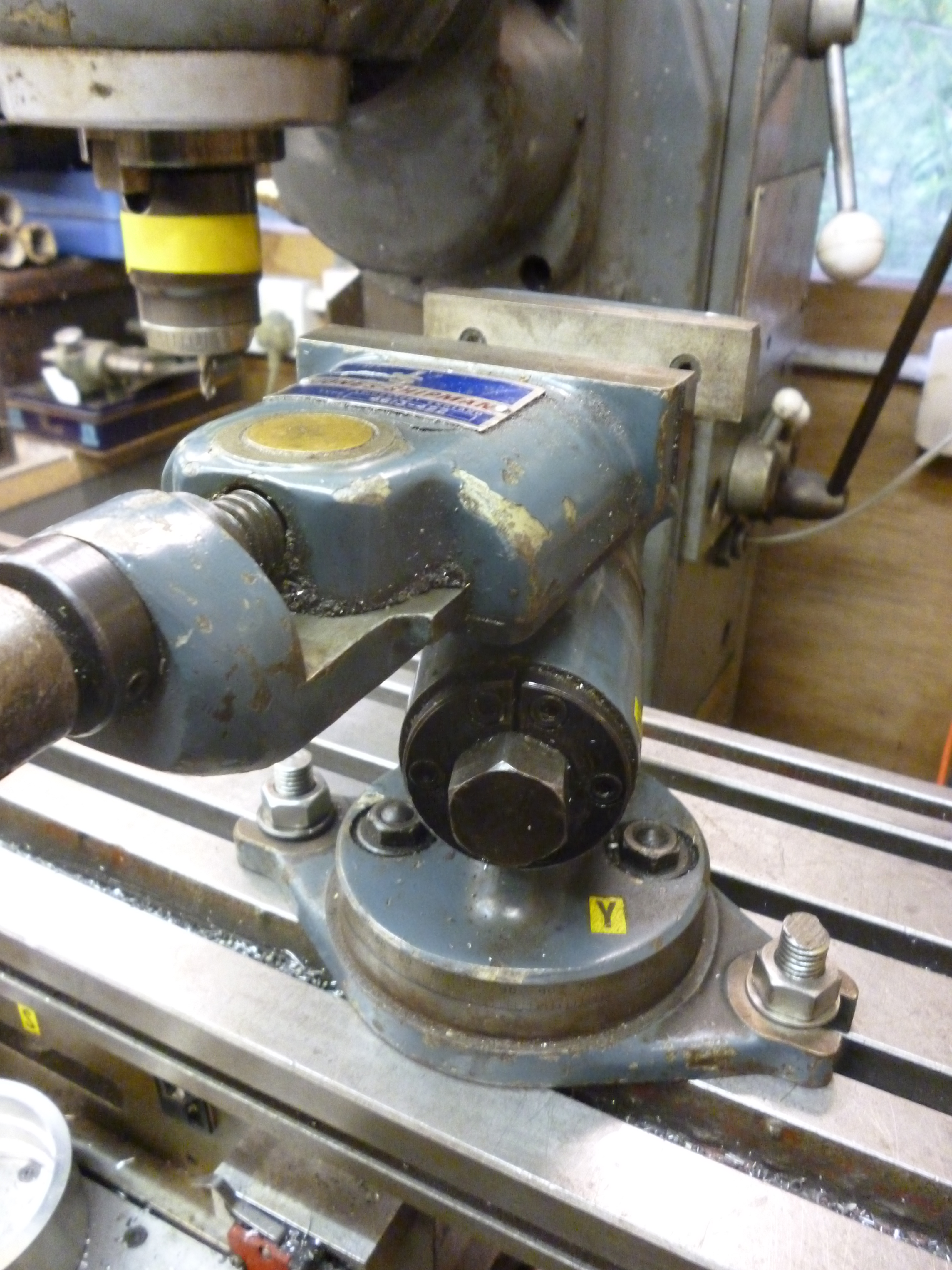
612 the problem with a swivel, tilt and swivel vice
Fig The problem when aligning a swivel, tilt and swivel vice 612
This can be solved by tilting the jaws one way so that they are vertical in the sense that the top surface of the fixed jaw is vertical at the same time that inside surface of the jaw is also vertical. doing this sets the top swivel to zero. Then, if the middle tilt is used to set the jaw horizontal, the bottom swivel is used to set the jaw parallel to the x axis of the milling table.
This is further complicated by the nature of the tilt and second swivel joints. They are both made with tapers. They both have a useful feature whereby the taper is forced apart when the jaw is loosened with a spanner. But the other consequence of his is it is very difficult to adjust these joints precisely by tapping with a soft headed mallet.
