Tools – microscopes – introduction
Everyone must be familiar with the use of a single lens to magnify everyday objects. Single lens are often used to magnify scales, for example on a height gauge.
fig magnifying glass being used on a height gauge
A microscope is simply the same sort of device but instead uses two lens to achieve greater magnification. These lenses are often mounted on either end of a tube. This only magnifies if looked through the right way round. In this case, the lens near the object being looked at is the objective lens and the lens near the users eye is the eyepiece.
fig microscope made from and eyepiece and an objective
Most lenses suffer from inherent imperfections. To get round some of these what often appears to be a single lens might be a group of lenses.
the simplest microscope of use to us will consist of an eyepiece. This usually consists of two lenses in a short tube about 50mm long.

4389 eyepiece 1
fig typical eyepiece
This will fit n a longer tube at the end of which is the objective. This is a specially made metal tube that screws into the body of the microscope.The overall length is about 160mm.
fig eyepiece, tube and objective on a microscope
Some means of holding all of this accurately is required. This is because the object being viewed will only be in focus at one particular point from the end of the microscope. This adjustment is often done using a rack and pinion mechanism. Because of this the microscope will only work if the object is at right angles to the body of the microscope.For the same reason it is essential that there is some mechanism to control the distance between the object and the objective lens.
Magnification
The overall magnification of a microscope is, roughly, the magnification produced by the magnification produced by the eyepiece. The result is that the overall magnification is the product of these two. Most eyepieces and objectives are marked with the magnification of each of these. For example if the eyepiece is x 5 and the objective is x 2 then the overall magnification will be x 10.

fig markings on an eyepiece and an objective
Graticules
Where the size of the object has to be measured then one way of doing this is to fit a graticules somewhere between the objective and the eye.This is possible because the are places along the length of the microscope where a graticule will be in focus but nowhere else. This brings up the problem of eyepieces. The eyepiece might appear quite simple but the most common (and popular because it is cheap to produce) is credited to being designed by Huygens way back in the 1600’s. With this type of eyepiece the graticule has to be at the right place between the two lenses. If the position of the graticule has to be adjusted it can only be adjusted by adjusting the position of the whole eyepiece.
Graticules are scales. Sometimes along one axis or sometimes both. But it is also possible to have graticules that are outlines of certain shape. One very common one is outlines of threads another is of angles and small circles.
Lighting
Most of the microscopes that exist were made for use in the biological sciences. In these cases the object is transparent or cut so thin as to be transparent. This means it can be most easily illiuminated from underneath. Where the object is not transparent it needs to be lit from above. One exception is where the outline of a solid object is of interest.
Inversion of the image
In all microscopes, unless something is done to correct it, the image seen is upside down and back to front.
Different uses for microscopes
Simple microscope
a it is often useful to have a microscope just to make it possible to see something that is very small.
examples of this are the:
cutting edge of a cutter
finding a small spllinter of metal in the skin
This can be done with the simplest of microscopes. However it is quite useful to use a binocular microscope. This enables the object to be viewed using both eyes. It creates a more three dimensional feel to the image.
Simple microscope – The binocular microscope
Binocular microscopes as shown below are very common and easy to buy on eBay. These were often used by students to do dissections.

4391 binocular microscope
fig binocular microscope.
Key features are that though the object is horizontal the eyepieces are tilted to a more natural angle. The image is inverted using prisms. These are never fitted with graticules or micrometer heads or x/y tables.
These are often but not always fitted with turrets with three pairs of objectives.
Though the whole of the microscope moving up/down in order to be focused there is a separate focusing device on just one of the eyepieces.
It is not difficult to take photos of images seen using a microscope. This works with modern digital cameras because it is easy to see if the image is in focus before one takes the photo.
The way to see this is that the optics of the eye closely parallel those of the camera. There is one lens (well sort of) and the image has to focus on a light sensitive plate.
The method is to make a tube that fits on the eyepiece of the microscope one end. It then has a hole in it that fits the lens of the camera when it is out. Doing this means the image the camera is going to record can be seen by the user. The user has to focus the microscope till the image is in focus.
fig camera fitted to a microscope using just a simple tube
WARNING – ITS IS ONLY THE TUBE HOLDING THE LENS ON THE CAMERA HOLDING IT PLACE _ ON MANY CAMERAS THIS TUBE WILL BE RETRACTED AUTOMATICALLY AFTER A CERTAIN TIME AND THE CAMERA WILL FALL OFF
Toolmaker’s microscope
A toolmaker’s microscope is designed so relatively small objects can be accurately measured. It is not possible to measure large enough distances by simply moving a graticule. Instead the object is fitted on to an x/y table. This can usually move by means of micrometer heads by up to 50mm. If measuring angles is important then there would be a circular plate fitted on top of the x/y table to measure them.
Either way, it would be possible to illuminate the object from above or below.
There would be a choice of graticules that fitted into the eyepiece (or near it) These could be used compare threads etc.
When measuring screw threads it is often necessary to check the form of the thread at an angle. On some toolmakers microscopes this is done by tilting the column on which the eyepiece is held. On other a special set of centers which can be tiled is fitted to the x/y table. These centers are then tilted.
Metallurgical microscope
Microscopes are used by metallurgist to look at the micro structure of metals. Usually the metal surface is etched to bring our certain features. Clearly the objects of concern here are not transparent and so the object has to be lit from above.
One simple method for doing this is to have a lamp on the side of the microscope tube The light enters the tube. At this point there is a bean splitter. This turns the light down, towards the objective. It goes through the objective the (wrong) way and is reflected off the image back up the tube. It goes straight through the bean splitter and produces the image the user sees.
fig an old metallurgical microscope
Centering microscope
The centering microscope is primarily designed for use on a milling machine. The idea is that it fits in the socket of the spindle. The eyepiece branches off to where the user can look into it. It contains a graticule.
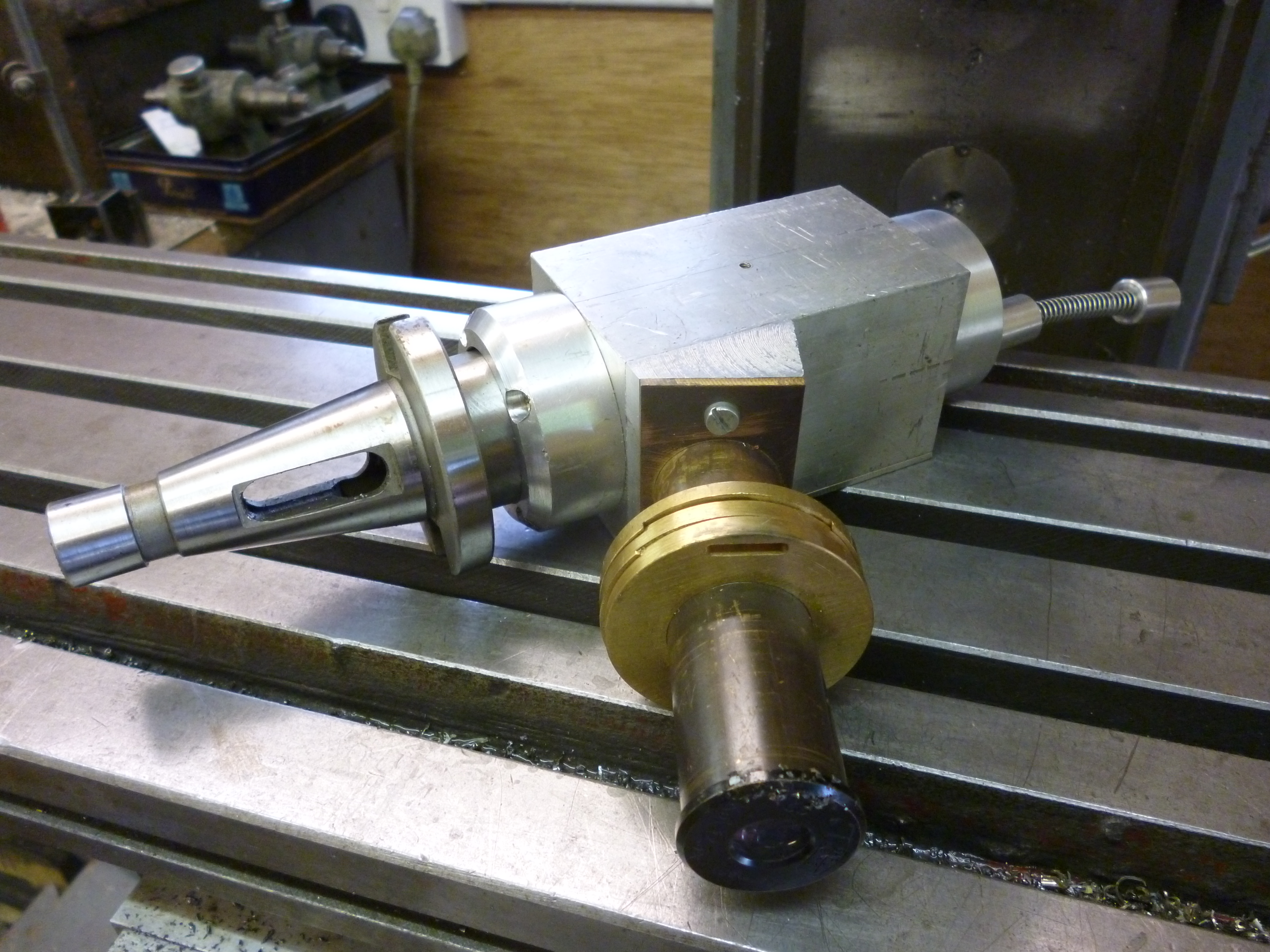
210 centering microscope 4
fig centering microscope
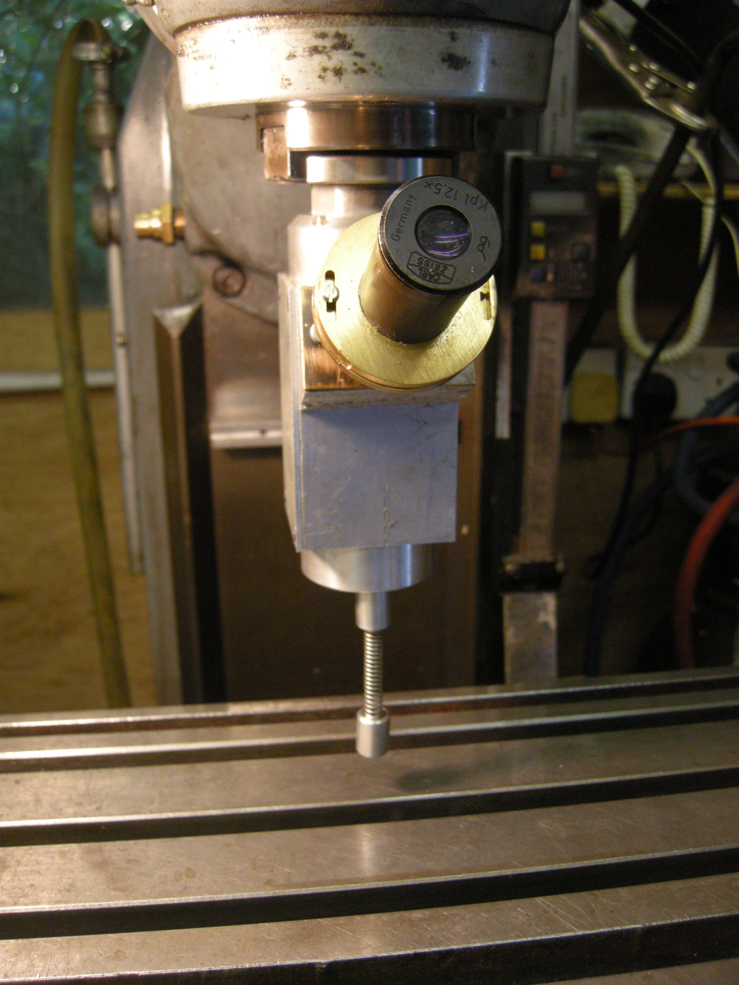
225 microscope fitted
fig centering microscope fitted
In this case the graticule is in the eyepiece. This means it has to be aligned by moving the whole of the eyepiece in both the x and y directions. On this microscope the image is turned using a mirror. The image is still upside down and back to front.
The user has to set this up so that a point on the milling table directly in line with the axis of the spindle. There after any point on any workpiece can easily be set up to be centered with the spindle.
