go to the home page
go to the page above this one
DTI on a dovetailed arm
Another type of centering tool is simply a DTI on an arm that fits into the spindle socket. The DTI is the lever type. This can be used to center all but the smallest sizes of round shapes either internally or externally.
A key feature of this type of tool is that the movement of the probe on the arm is done by means of a screw mechanism. This means it can be moved by very small amounts accurately.
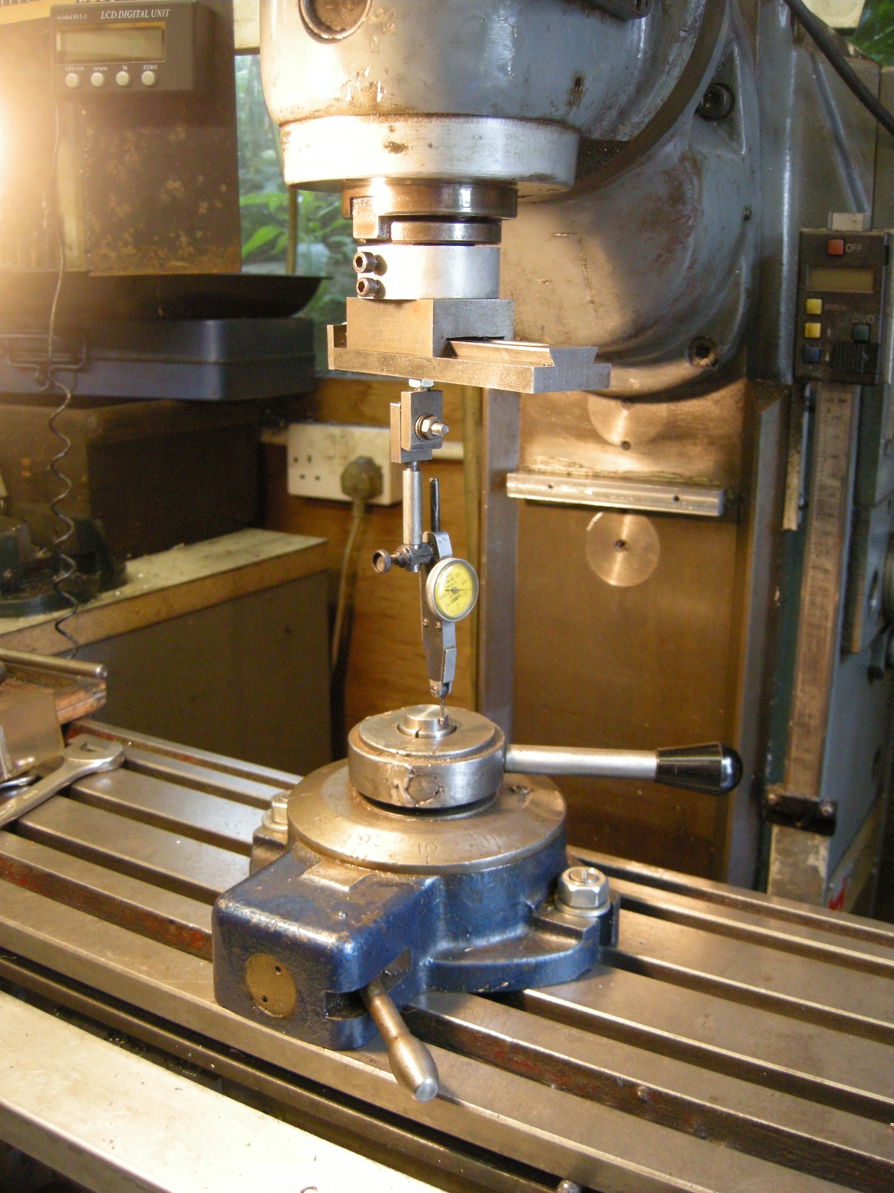
212 dti on a dovetailed arm 1
Fig. DTI on arm alignment tool 212
Usually the reading is made on the left (or right) and then the right (or left) the workpiece has to be moved and the arm adjusted till both readings are the same. This has to be done at the widest part of the round object.
The first problem with this is that as the tool rotates so does the face of the DTI. The best arrangement is that the DTI faces outwards. In practice, it is only necessary to read the DTI when it is facing left, then with it facing right and adjusted till it is correct both left and right. Then the workpiece is moved in or out till the front reading is correct. In all three of these positions it is easy to read.
It is essential that the position of the DTI on the arm can be adjusted very precisely. Using a dovetail mechanism with a screw to control the movement of the DTI does this. To cope with holes of very different sizes the DTI can be fitted at any one of a number of positions on the dovetail.

501 dti on arm underneath
Fig. holes for rough setting of DTI on an arm tool 501
The second problem is that the line from the first reading to the second must pass through the axis of the spindle to be accurate. This means there must be some adjustment in the left/right movement of the dovetail arm. Any errors here become very important as the diameter of the object being measured gets smaller. In the picture above, it can be seen that the fitting of the DTI has a joint in it so it can be moved left or right.
The height of the whole device is quite high. This particular model has since been modified to reduce this height. Where there is a shortage of height between the workpiece and the cutter it can be difficult to fit the DTI on an arm device. One trick is to reduce the height of it, but only while fitting it, by swivelling the joint so the DTI bit is horizontal. After it has been fitted into the socket the DTI can be set so it is vertical. The same procedure can be used when removing it.
It is far easier if, initially, the tip of the lever is just above the height of the workpiece. Using this as a guide the workpiece can be moved and the arm can be adjusted till it is nearly right. Then the workpiece can be raised (or quill lowered). Then the alignment can be completed with the side of the tip touching the workpiece or workholding device.
The DTI is moved out till it touches one side of the hole on the x-axis. Check that the point of contact is at the extreme left (or extreme right) of the hole. This can be done by moving the hole in and out in the y direction till a minimum (or maximum) is found. At this point the y-axis movement should be locked. A note is made of the reading on the DTI. The arm with the DTI is then rotated through 180º. At this point the maximum or minimum is found. A reading is made. The difference in the two readings is twice the error in the position of the hole along this x-axis. The table is moved by this amount in the appropriate direction. This “amount” is not measured with the graduations on the lead screw because of any potential backlash. But it can be read perfectly well without any problems merely by reading the movement on the DTI. This process is repeated. Almost immediately the two readings should be the same. When the two readings on the DTI are the same then the axis of the spindle coincides with the center of the circle.
Doing this means that the hole should be almost perfectly aligned in the y direction. This can be tested by turning the arm only 90º and the reading on it should be exactly the same as at the left and right positions along the x direction.
If this arm is fitted with a DTI of the plunger type instead of the lever type then it can be used for tramming the vertical head.
fig dti on arm device fitted with plunger type dti
This device is for use on the milling machine. The same sort of problem – aligning internal and external round shapes – on the lathe can be solved by using a dti on a magnetic stand mounted on the cross slide.
