How did the Romans work out the slope/gradient of their aqueducts?
Many writers declare themselves to be baffled at how the Romans could build aqueducts with very gradual slopes. The aqueduct that goes from Uzes to Nimes over the Pont du Gard has a difference in height from start to finish of about 10m. Yet the length is 15km. That is a slope of less than 1 in 1000.
The Romans did have a device, the chorobates, that could set a level surface. It was a table with a slot in it that was filled with water in it. But this would not have been accurate enough to layout an aqueduct with such a small slope. The problem with this is that even if the accuracy was one part in 10,000, each reading would introduce an error. Since the range over which it could manage this error would be far smaller than the length of the aqueduct the number of readings would be so large that the sum of the errors could make the results useless.
The problem would seem to be that there is an assumption that until one can survey the path of the aqueduct one cannot make it. But this has to be wrong.
The solution to this problem is to use the aqueduct itself to set the slope of the aqueduct.
Before the building starts there is one survey that is needed. It is to determine that the height of the source of the water is sufficiently above the point where the water will be delivered to make it worth starting the aqueduct. This does not have to be very accurate.
Suppose we are confident that the difference in height is, allowing for errors, sufficient. Then we can start building the aqueduct. It will be seen, from the method proposed, that we have to start at the source end. We can build further away but only to a limited height because we are not sure what the final height will be at any other points – yet..
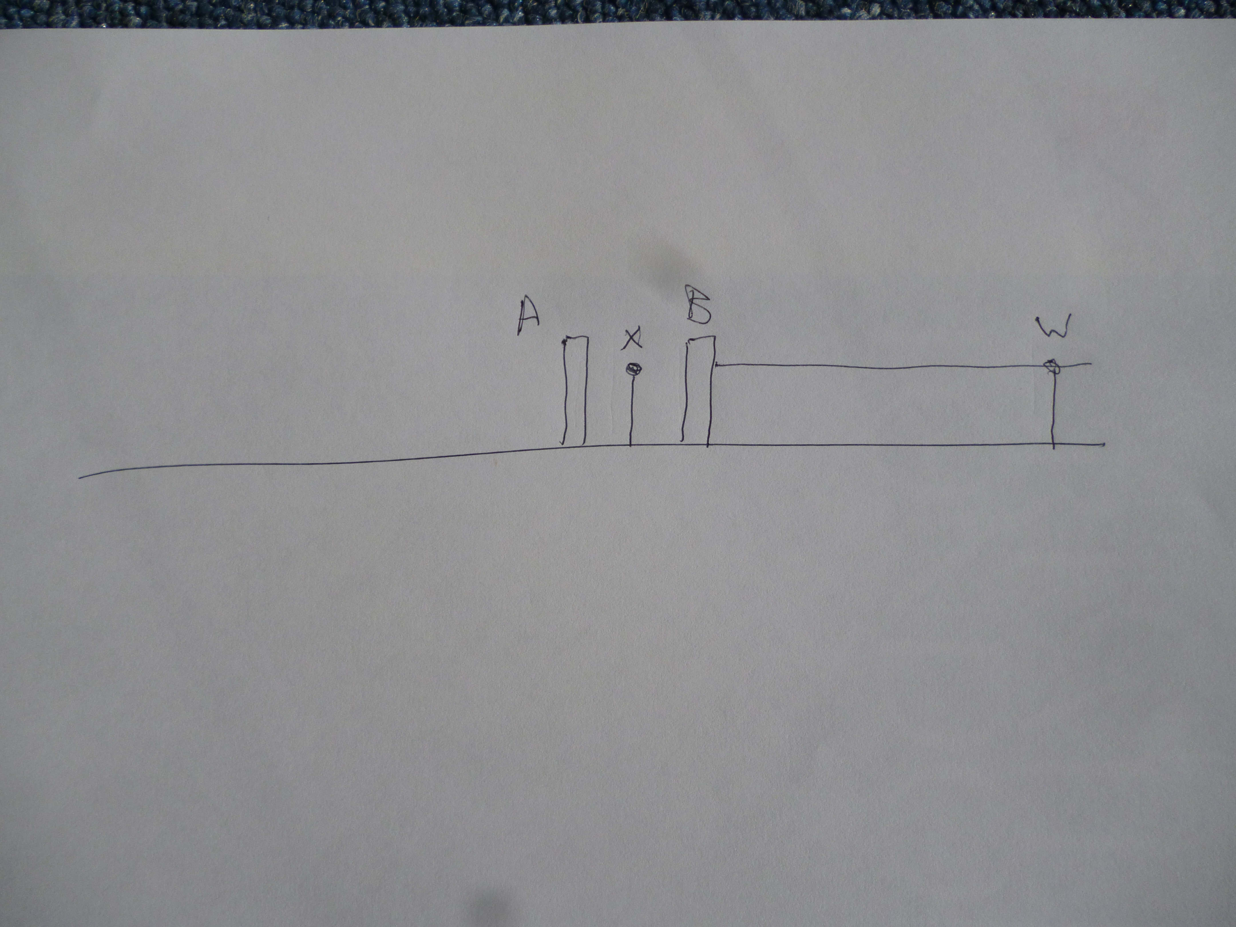
The way it is done is that a length, say, about 1km, is built at the level of the source. The bottom of the trough is nominally flat. This length It is blocked off at its “lower” end, ie at “A” and is allowed to fill with water. It does not have to be filled to its full working depth but enough to clearly cover the bottom of it.

The long line here represents the bottom of the trough of the aqueduct.
At this stage two depth markers are fitted to mark the level of the water, ie, markers w and x.
A new block is fitted at “B”. The depth markers “W” and “X” are untouched.
Meanwhile the next kilometre of aqueduct has been built to the same height less about 10mm. This is blocked off at the low end at “C”. The block, “A”, at the low end of the first kilometre is removed. A new depth marker, “Y” is fitted near marker “X” but about 10mm lower.

Water is allowed to fill the second kilometre. This time though it is only allowed to fill to, say, 10mm below the level before. A depth marker, “Z” is fitted to the lower end of the second kilometre at the new depth, ie 10mm below the depth at the low end of the last kilometre.

This is repeated till the far end of the aqueduct has been built.
This method will have not problems with an aqueduct that follows a very irregular path.
In practice it would seem likely that many more depth markers would be used so the bottom of each 1km section would be flat.
The height when the aqueduct reaches it destination is unpredictable. But any height above the minimum required can be seen to be a bonus.

Before they built the aqueduct how did they know there would be enough or any slope between the start and end points? GPS? I’m an old guy that just recently started machining. I’ve been going to YouTube university to learn the basics. Thanks to people like you & the availability of cheap import tools I’ve managed to acquire and learn to use some of the tools of the trade.
thanks
they had surveying instruments. All of this is covered in “roman Aqueducts and Water Supply” by A Trevor Hodge. These are usually adequate to show that there is a reasonable height difference. But they are not adequate to get the slope accurately enough. I shall try and go back and edit the webpage to explain this.
john f
Similar methods could have been used for all open aqueducts, but wouldn’t work as well in the tight quarters of the Persian kariz, many of which travel underground for miles…
If that is how it was done, the Roman aqueducts should be without slope for much of their distance, being “level” for hundreds of meters at a time.
I completely agree with you. But I haven’t got round to trying to check this against photos I have of aqueducts.
I think, near the top, the surface would go down in steps that were not noticeable, say 10-30mm. This would be smoothed
at the slope required with cement then the final stonework carrying the water would be sloped.
john f
sorry about the delay.
I think you are probably right. I really need to have a look at one close up. but there aren’t any useful remains of one in Britain and covid….
With colleagues in Naples (Associazione Cocceius, find us on Facebook) we have been studying the Augusta Aqueduct in Campania for over 10 years. I constantly badger the active guys who go down the tunnels (not me, I am too old for that) to look for evidence on your theory. All the significant stretches, 500m plus, all in tunnels as little remains above ground, we have examined either show no steps, or the sinter (deposited calcium carbonate has covered over any traces), but I will let you know if we ever find anything.
Hi,
Thank you for your message. I shall have to go to the British Libraryto look up the book you mention – too exspensiveto buy.
Unfortuneately there are almost no roman aqueducts of interest in the uk. Just before covid I did go to see the aqueductin tarragona and, on another holiday, I wenttov see some other near Lyons in france.
I suspect most of the aqueducts are built in sections that are flat at thebottom of the chaneel then given a slope using cement. I think they would only finish that section starting from the high endofthe aqueduct. Subsequent sections would be flat but start a little lower than the top of the previous section and the sloped with cement. This might be done every, say, kilometre. Being in the right place, with the right kit. It should be possible to see the change in height. I suspect it would be about the thickness of one course of stonework at thetop of the aqueduct.
Hope this helps. Keep in touch. I am not renewing my subscription for this wwebsite soon so make sureyou have my email address – johnsf23@hotmail.com
I’ve long pondered this.
The way you said is what I would do if stranded on a desert island.
However, as a 70 years young precision machinist, I’ve long been fascinated by the accuracy of old methods, and what can be achieved by hand.
Not sure of they used something like this, but a pendulum weighted optical leveling device, could achieve reasonable INITIAL levels. Just a guess.
No plastic pipes for water gauges, yes they had lead, but was anything else available?
However, wouldn’t an easier way to survey have been to lay clay tile troughs to get the correct levels, THEN build the final structure once determined?
Any optical system withoutmagnification will have a limited range and limited accuracy. This means a large
number of readings will be needed and each will introduce an error. In what i suggested the aqueduct is the pipe
and however long it is 100% accurate for this distance. It even allows for the curvature of the earth!