Go to home page
Go to page above this one “Toolholders and cutters – links”
Cutters that fit toolholders for vertical milling
Endmill
The endmill and its close relative, the slot drill, are the most commonly used cutters used in the vertical mode.
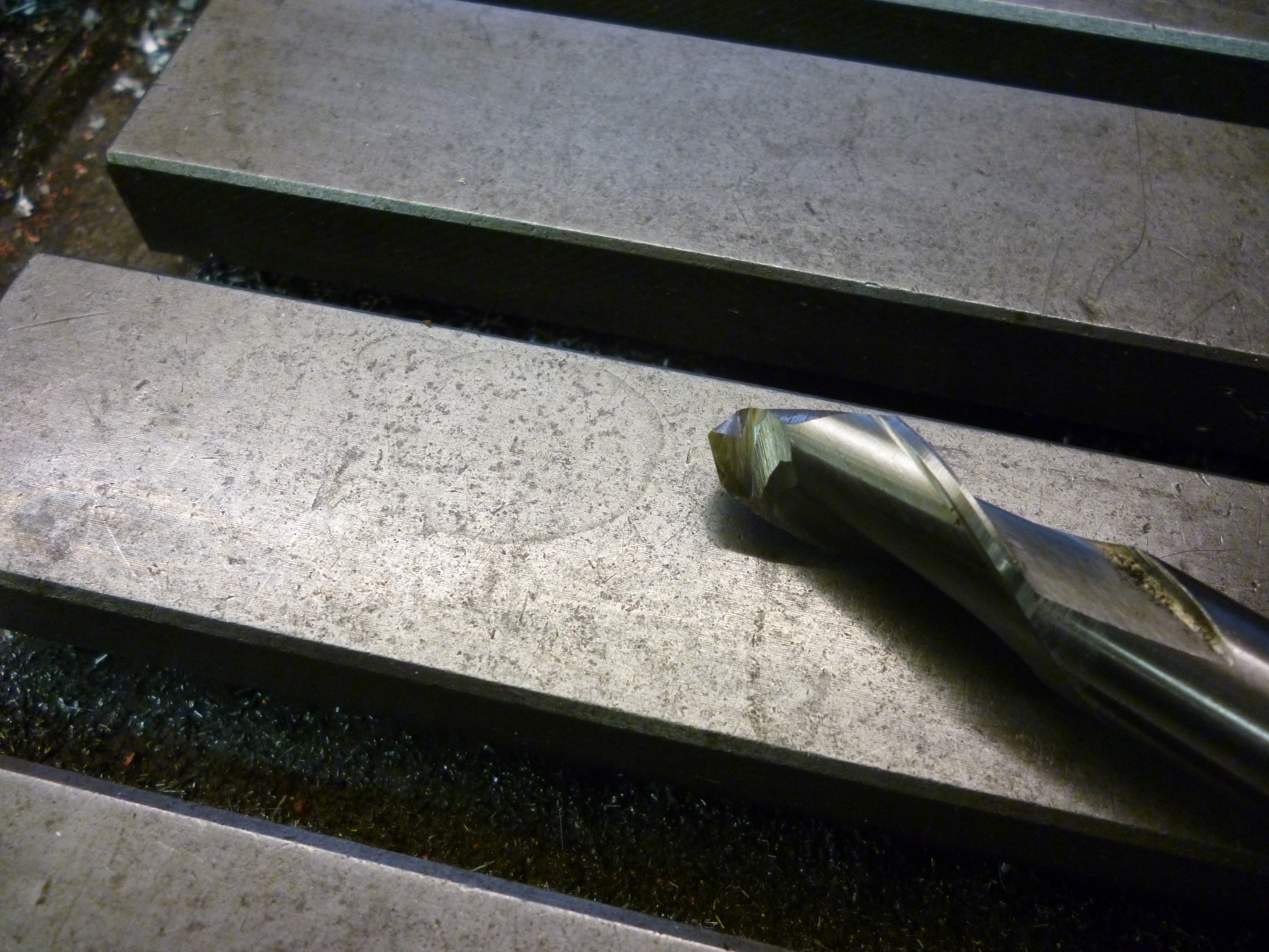
The traditional endmill usually has four flutes. It has cutting edges on the end of each flute but these do not reach into the center of the end.

- fig – An endmill – 3

There is a hollow in the center, which has very limited depth – a few millimetres. This means that this cutter cannot cut straight down – plunge milling. If the center was a clean hole the cutter could cut downwards but the hole has shallow sides. This greatly limits how far the cutter can cut downwards. It is possible to cut a slot by moving the cutter along as it is fed slowly downwards but it would be far better to do this using a slot drill. In general, with an endmill, cuts usually have to start from an edge.
The endmill can cut in two ways. It can cut using the edges on its end. Though, even here, the ends of the flutes are involved in the cutting. Flat surfaces would usually be cut like this. Alternatively it is very good for cutting round the edges of a workpiece – profiling. In this case just the edges of the flutes would be doing the cutting and the ends of the flutes would not be cutting at all.

- A carbide endmill – 737

Fig. Endmills with inserts
In recent times it has become possible to buy endmills where the flutes do meet in the middle. There is no hollow. These are designed to give a better finish.

- The end of a finishing endmill – 629

Endmills – bending and breaking
All endmill are simply bits of metal and like all bits of metal, if push hard enough, can bend or even break. Since cutters are very hard they are also very brittle.
For a given force the bending will depend upon the length and width of the endmill. The longer it is the more it will bend. On the other hand the smaller its diameter the more it will bend. At the same time the greater the force applied to it the greater its tendency to bend though in this case how it will bend is not simple.
The smallest diameter of the shank of an endmill that will fit an Autolock chuck is 6mm. For any size shank there will be cutters that are wider than the shank and cutters that are narrower than the shank. It does not follow that a cutter is necessarily the diameter of the shank. Furthermore if a cutter like this is sharpened the diameter of the cutting part is reduced from what it was.
Usually sizes less than 6mm are only supplied on 6mm shanks. Going the other way it is only the cutters with the bigger size shanks that might have a slightly bigger diameter cutting part.
It is quite easy to get endmill, which has a cutting part only 1.5mm in diameter. These break very easily. There is nothing to say it is about to break except some little clicks that are probably the tool being bent and then suddenly released. When it goes “ping” it is gone forever.
If you mill a slot with a small endmill, say, 6mm diameter, you will find the slot will not be exactly straight. It will bend and cut to one side when going one way and then to the other side when coming back. At the ends it will twist slightly depending upon the forces acting on the tool. This is because the cutter is bending. The solution to this is to reduce the forces on the cutter. This is done by reducing the amount of metal being cut per second – a shallower cut or slower cut or both.
Very small endmills touching a surface will wander around and make a mark much bigger than the end of the endmill. The only way to use such a cut is to start with the very slightest of cuts, a few hundredths. until there is a groove say 0.5mm deep. This groove will guide the endmill and will allow the same cutter to make much deeper cuts.
Small endmills are easily broken usually because they are asked to cut too much, too fast. Larger endmill will usually break because the workpiece moves in the vice and the force on the endmill when it catches the workpiece is too much.
It is usually best to use the widest and shortest endmill that will fit the job in hand. One reason for using longer endmills is that it might make it easier to see what is going on.
Sometimes it is possible to cut the slot narrower than required and then cut the sides to the final width.
Though endmills are designed to be able to cut using their sides, if it is an endmill that has been home sharpened many times the end will be sharper than the sides. It will often be better to cut using the end rather than the sides.
A sure sign that the endmill is blunt is that it makes a little ridge of metal in front of itself as it moves along.
Fig. 43 – blunt endmill cutting
It is always a false economy to use a blunt tool.
ALWAYS USE A SHARP TOOL.
FC3 endmills
FC3 endmills are small endmills with three flutes that are designed to be used once. When they are no longer sharp they are meant to be thrown away.
They are usually held in side lock type chucks.
They can be held in any ER type collet.
It is possible to get an adapter to take one of these that will fit into an Autolock chuck.
1215 autolock chuck with FC3 adapter
fig – Clarkson Autolock FC3 Adapter
See MEW 190 p57
Extra length endmills
It is possible to get endmills that are longer than the usual length. These can be used to cut the sides of workpieces with the endmill in the vertical position.
Of course, since they are extra long, there is a risk that they might bend more than expected. The way round this is never to make deep cuts along the full length of the cutter.
Suppose an edge is 60mm deep and it has to be milled a few millimetres off leaving a good finish. The method is to machine it in steps. For example, it is machined to nearly the full distance but only, say, 15mm deep. Then it is machined to the same distance but down to 30mm and so on. When the whole surface has been milled to nearly the final distance, one or more final passes are made machining the full deep but only skimming the surface and so leaving a good finish.
Endmills and uphill and downhill milling
with any milling cutter it is possible for a cutting edge to be moving against the movement of the workpiece or with it. This effect is most obvious when horizontal milling. In this case it is quite that all the cuts are against the movement of the workpiece. This is known as uphill milling. In this case for any one cutting edge, it will start with a thin cut. As the workpiece moves towards the cutter, the thickness of the cut will get thicker. It will be at its thickest just as it leaves the workpiece.
The advantage of this is that since the cutter is pushing against the workpiece this takes up any play in the system. However the finish produced is better if the cut is thinnest as the cutter leaves the workpiece. This can be done by downhill milling. In this case the cutting edge is moving in the same direction as the workpiece. The cut statrs thick and ends thin.
This will only work is the cutting force is very light because of the backlash problem. however some machines have backlash compensation so they can do this.
If an endmill is cutting mainly with the end of the flutes and the whole width of its end, then part will be cutting uphill whilst part is cutting downhill. This will work without any trouble. If roughly half the end is used it will have to be uphill milling – the cutting part of the endmill must be moving against the motion of the workpiece.
If the flutes are doing all of the cutting they must be cutting against the motion of the workpiece. Incidentally, when doing this, if the flutes are sharp, they will cut pieces of swarf the length of the cutting edge. However they will give a better finish if they cut downhill. This can be done if the cut is very, very light. But then that is all that is needed for a finishing cut.
This is especially true on aluminium. Here bits of swarf become welded to the workpiece when uphill milling but completely disappear when downhill milling.
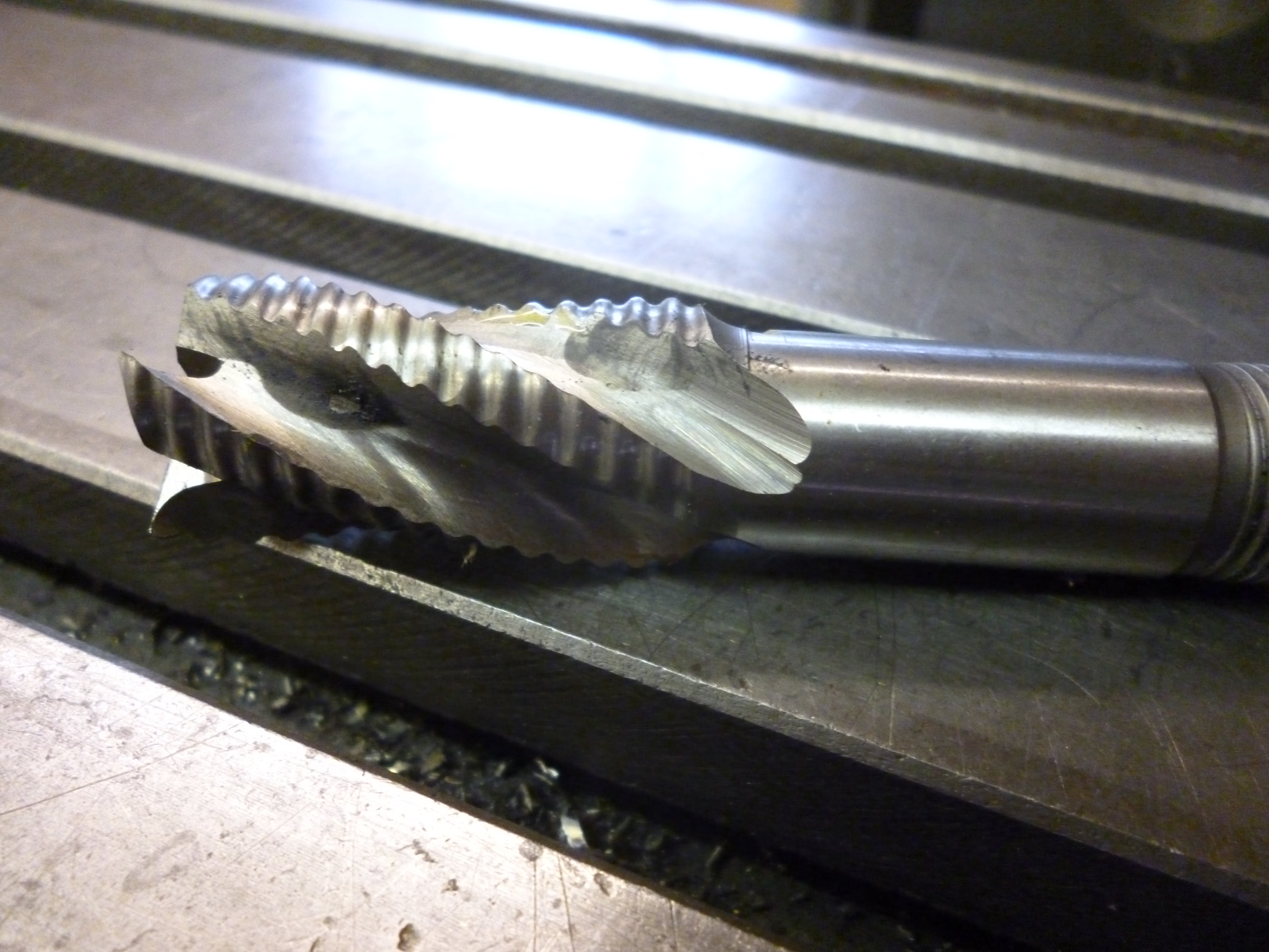
Rippers
There is a special form of endmill known as a roughing cutter or ripper. This has wavy edges along the flutes. The advantage of this is when the cutting is done using the flutes. This significantly increases the speed with which it can remove metal. Though it appears to have a very jagged edge it does actually cut fairly smooth surfaces, though not as smooth as an endmill would.

- Ripper – 15
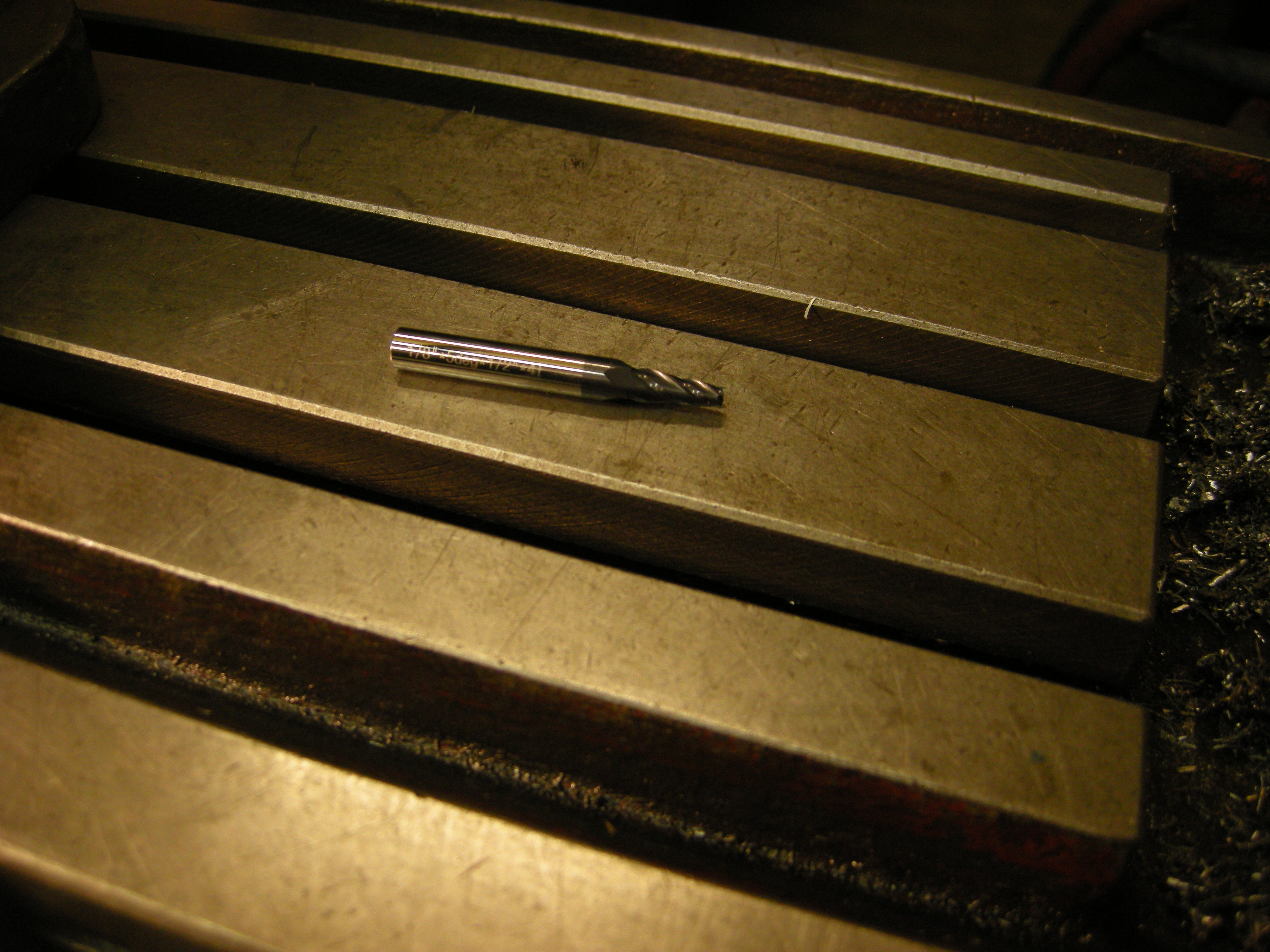
Tapered endmills
There are also endmills with very slight tapers. These are for milling patterns (as used for making moulds when casting) where a slight angle ensures the pattern can be extracted from the sand. Using a tapered endmill means that whatever shape is being cut, all of the edges will have the same angle regardless of the direction of the cut. If the milling head is tilted (in the x/z plane) to get a similar effect it will only give the required angle for cuts in the y-axis direction.

- Tapered end mill – 311
Other uses for endmills
Endmills and slot drills (see next) are usually made of solid HSS or solid carbide. They can be used as a source of solid round pieces of either of these materials.
The larger diameters come in extra long lengths but there is a lot of very hard material to remove. The smallest sizes, i.e. 6mm or 1/4inch, are the most useful. They can be used for making cutters for boring tools and for fly cutters.
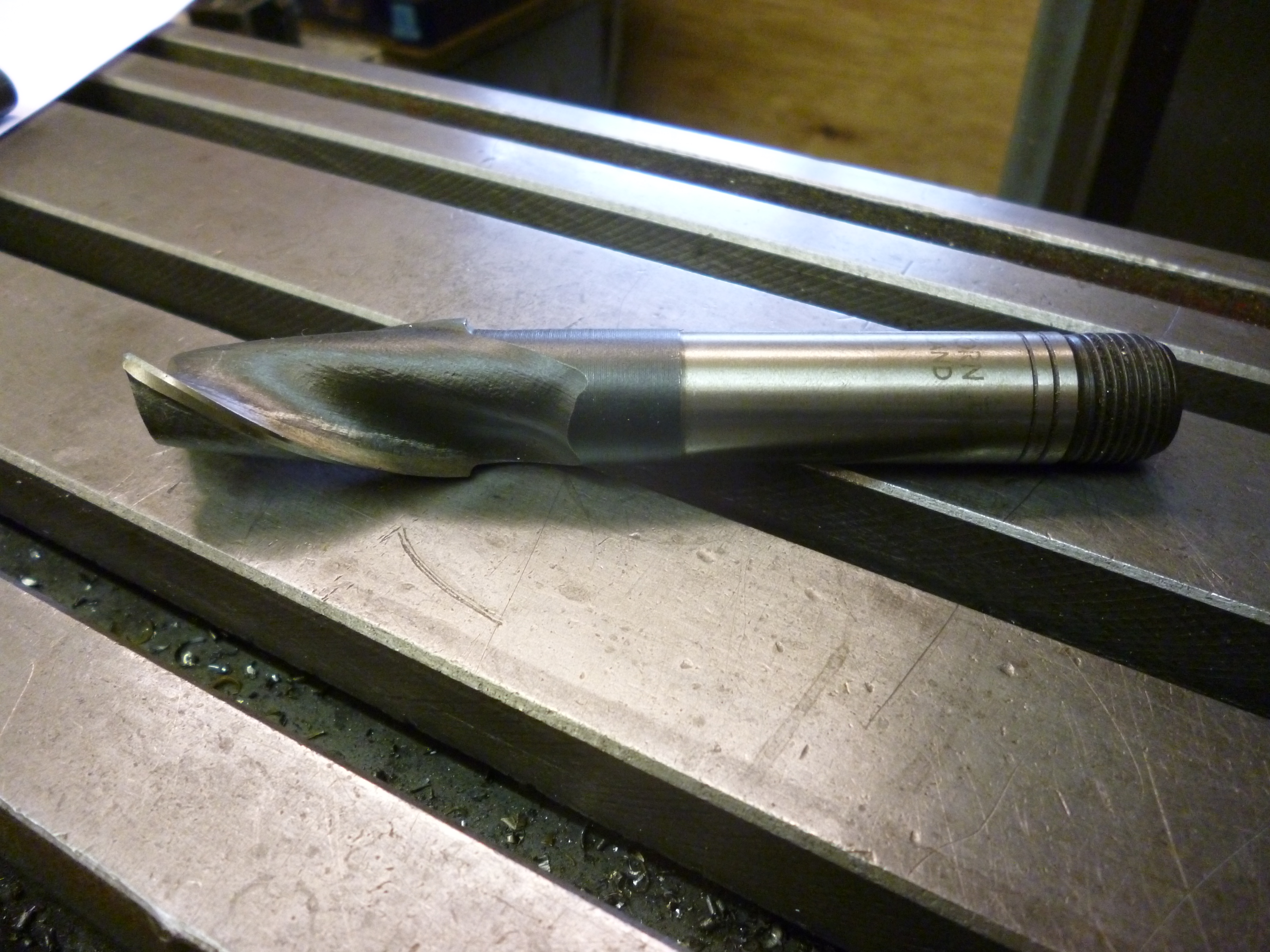
Slot drills
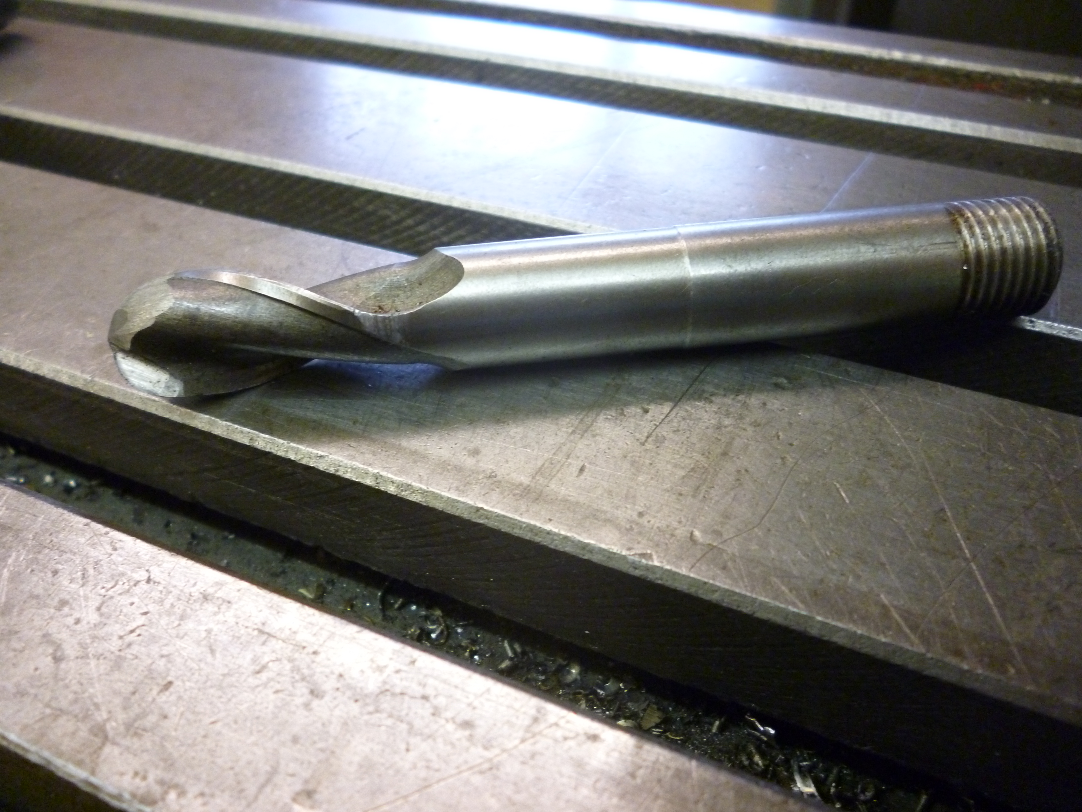
The slot drill is like the endmill except it has only two flutes. It is probably less rigid because of this. Consequently the smallest slot drills that can be bought are significantly larger than the smallest endmills that can be bought.
The slot drill is fundamentally different from the endmill in that one of the flutes has a cutting edge on the end that cuts just further than the center of the cutter. This means that it can be used to cut straight, downwards into the workpiece. This is known as plunge milling.

- slot drill – 17
Milling slots in a workpiece that are open at the ends are best done with slitting saws or side and face cutters – see later.
A slot drill can be used to “drill” holes that could not be drilled using an ordinary drill. For example a semicircular hole could easily be drilled in the side of a workpiece using a slot drill. They can be used to drill flats on surfaces that are not flat. It would then be possible to use an ordinary drill to drill the hole. It is also possible to drill “half” a hole down the side of a piece of metal.
With small slot drills this becomes more difficult. One trick is to put a piece of same material against the edge of the workpiece so the slot drill is “drilling” “solid” metal.
Fig. 47 milling solid metal
Modifying slot drills for other uses
Because it has only two flutes it is much easier to grind slot drills. This is not only an advantage when sharpening the slot drill but it also means it is practical to grind slot drills into special cutting tools. Where this is used to make a conventional form of cutter these are covered later.
The easiest case is where the existing flutes of the slot drill are kept, in some way, as the new cutting edges. This is the case where it is used to make a T-slot cutter. The more difficult cases are where a new cutting edge has to be formed.
The general solution to this is to grind away almost all of anything that might be in the way. This is done till the side of the edge is about 1mm thick. This is then ground, even with a flat surface, to give the necessary clearance. This, effectively, how ball ended mills are made commercially. See fig. ****
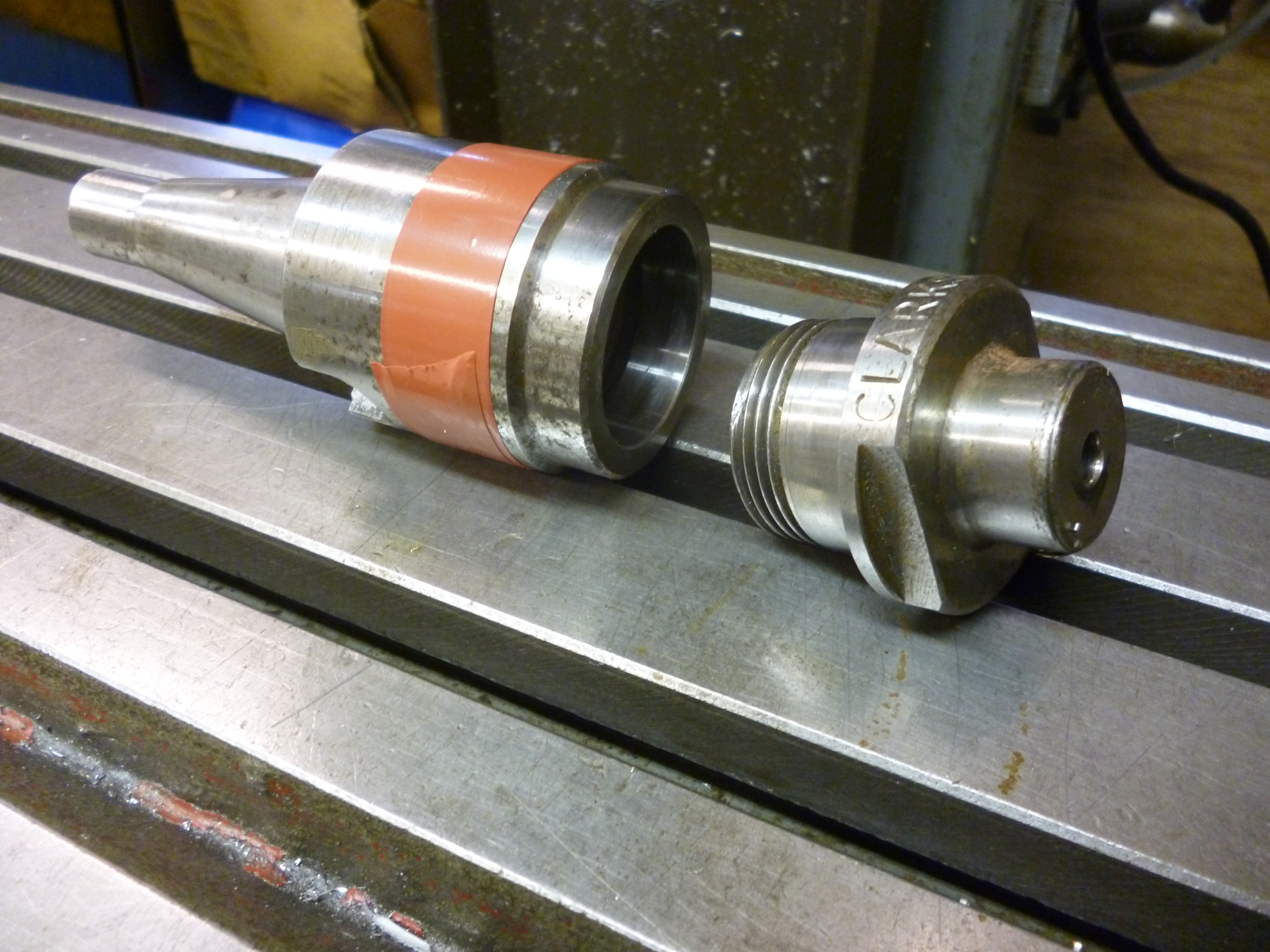
Slot drill ground to make spigot to fit Autolock chuck
With the Clarkson Autolock chuck the cutter can only be held properly if it has a suitable thread on the end of the shank. There are times when it is useful to have a blank rod that will fit the chuck. Such a rod can be made by grinding off the cutter part of an endmill or a slot drill. This is better done with a long series cutter.
Slot drill ground for cutting chamfers
A slot drill can easily be modified so it can be used to mill chamfers. Grind one side so it is out of the way. Grind the other side to give the angle required, usually 45º.

- Modified slot drill for cutting chamfers – 451

- Chamfer – 452

It is essential that there is adequate clearance at the back of the cutting edge.
It is essential that any edge of a workpiece that is to be chamfered is horizontal and parallel to the direction of cutting. Otherwise the chamfer will be tapered and the result will look worse than if it had never been chamfered at all.
Slot drill ground for cutting gear teeth
It is possible to grind a slot drill to a shape that can be used for cutting teeth on a gear wheel.
Slot drill ground for screw cutting
It can be very tiresome trying to cut very large threads on the lathe. It is also difficult to cut threads with very large pitches. But this is no problem on a milling machine. This is covered in details later. The trick is to grind a slot drill to form the shape of the space between the threads. It is not necessary to grind both sides of the slot drill – just use one side.
Ball ended cutters
Slot drills can also be bought that have been ground so as to have a round end. These are known as ball ended cutters. These can be used to cut a concave shape where the shape is the same as that of the cutter. This will cut a length with a concave arc of up to 180º.

- Ball ended cutter – 26
These cutters come in standard sizes. It is possible to make a fairly good round shape by making one cut with the cutter. A second cut is made with the cutter offset by the required amount. A third cut is then made with the cutter in the middle of the slot but cutting a very small amount deeper.
Fig – making wider round cuts
When cutting a long concave or convex surface by hand then a ball ended mill will give a better fit to a curved surface than an endmill or slot drill.
Very small ball cutters are useful for drilling hemispheres on the end of round rods for making rivets snaps. (This is most easily done in a lathe).
Radius cutters
The opposite of the ball-ended cutter is the radius cutter. This cuts a convex shape but only half of it at a time i.e. an arc of up to 90º.

- Radius cutter – 16

The flat bit at the bottom of the cutter does not cut. Usually one would use this cutter to cut anything up to a 90º segment of a circle but the bottom side of the segment would have had to been cut away already before using this cutter.
Whereas a ball ended cutter will cut a hollow hemisphere without the workpiece moving, a radius cutter can only a solid hemisphere if the workpiece is rotated as it is being milled.
For example, suppose a flywheel is laser cut from a piece of flat sheet. The spokes would now be square. If the spokes on the original wheel were round then a radius cutter could be used to cut four 90° arcs on each spoke to get the required shape.
Dovetail cutters
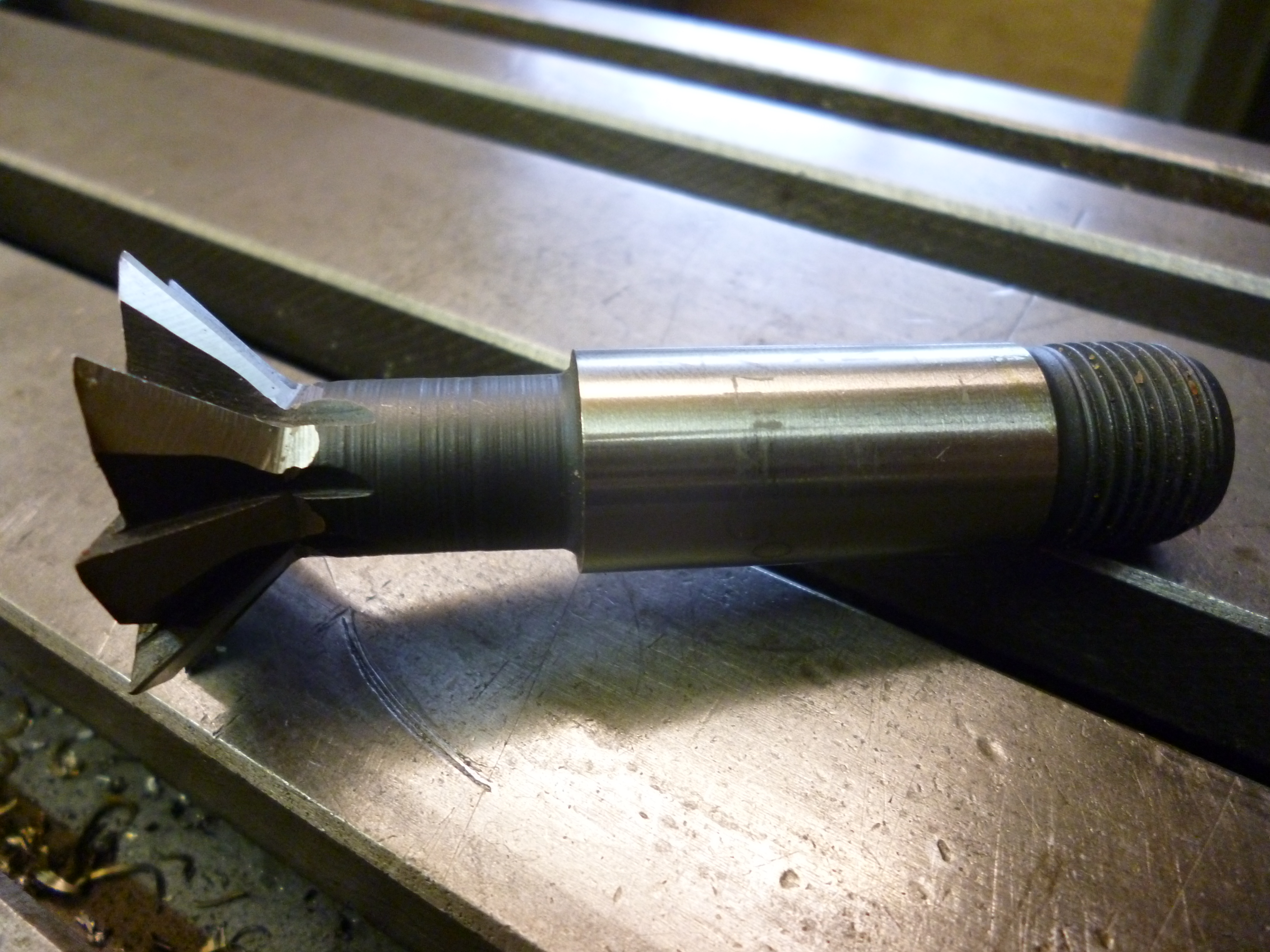
A really useful cutter is the dovetail cutter. This is, usually, easily the best, easiest and most accurate way to cut a dovetail. These usually come with 60º or 45º angles. All smaller dovetails have 60º angles. Larger ones are often 45º. But a popular make of small milling machine uses 55º.
A dovetail cutter can only cut a dovetail up to the height of the cutter. It is not possible to cut a dovetail whose angled sides are longer than the side of the cutting edge of the dovetail cutter. This means that, in general, buy the biggest one that will fit your machine. On the other hand it is essential that the width at the widest part of the dovetail will fit into the female part of the dovetails you are planning to machine.
These cutters are cannot be sharpened by hand. They can be sharpened using the simple jig outlined later.

- Dovetail cutter – 4
Though a dovetail cutter is worth having if only just for cutting dovetails it will be seen there are several other jobs that are also most easily done with a dovetail cutter.
See broach
See sawtooth clutch
Inverted dovetail cutter
Dovetail cutters also come in an inverted form. These are of limited use. But there is at least one job, making a tapered gib – see later, where they are one way though not the only way of doing the job.

- Inverted dovetail cutter – 203

Whereas with the usual dovetail cutter it is not possible to cut a dovetail that is deeper than the depth of the cutter, it is sometimes possible to use an inverted dovetail cutter to cut a dovetail of which the angled side is longer than the side of the cutter.
The effect of an inverted dovetail cutter can be achieved by using an endmill with the vertical head tilted. This does mean that the dovetail has to be cut along the y-axis (given not many users will have a vertical head that tilts in the y/z plane).
T-slot cutters
The T-slot cutter is used to cut T-slots. Using this type of cutter is usually the only way to cut T-slots on the milling machine.

- T-slot cutter – 204

A T-slot has to be cut in two stages. The central part of the T has to be cut using an endmill or slot drill. A T-slot cutter is then used to cut the cross part of the T. It has to do this in one pass. The feed has to be as slow as necessary.
T-slots come in standard sizes and so T-slot cutters are usually made to cut T-slots to these sizes. However it often seems to be the case that the cutters available for use do not produce a T-slot of the required size.
Obviously a T-slot cannot be small than the T-slot cutter that made it. With a T-slot cutter the cross part of the T can be made wider up to the point where the shank of the T-slot cutter rubs the side of the slot. Similarly the depth of the cross can be increased with the same cutter by doing more passes with the cutter at a lower height – subject to the shank not catching the workpiece.
Slot drill ground as T-slot cutter
T-slot cutters can quite easily be made from slot drills. This can be done using a tool and cutter grinder.
But, without any special equipment the process can be long and hazardous. The hazard can be reduced by making a holder for the slot drill so your hands do not end up near any sharp edges. All that has to be done is to grind away the flutes to form a shank. The shank only needs to be a bit longer than the depth of the bottom of the T (when it is inverted). This is best done with a grinding wheel the width of which is a bit less than the length of the required shank.
The most difficult part is checking that there are no parts of the cutter that will rub against the workpiece.
This works because the cutting bits that are needed are just the flutes, which are the original cutting edges.

- Slot drill ground to cut T-slots 425

Woodruff cutter
Very similar to the T-slot cutter is one for cutting Woodruff type keyways. A Woodruff key is almost a semi-circular disk. The Woodruff cutter cuts a part of a semi-circular hole in the side of a shaft. The Woodruff key fits into this hole and the top of the key fits into a slot in whatever has to be locked in position on this shaft.
Woodruff keys come in a very large number of standard sizes. But these are all imperial. For the key to work properly the radius of the cutter has to match the radius of the key. But even more important, the thickness of the cutter must make a slot that is a close fit for the key. Using the right thickness of cutter ensures the keyway will be the right width.
If a Woodruff cutter is sharpened it becomes slightly to small for the cutter it was made for. It can still be used but has to be wiggled to make the cut just a little bit bigger.
It will be seen that the T-slot cutter has a parallel shank. The Woodruff cutter has a curved shank. This limits its use for cutting T-slots.

- Woodruff cutter – 1

Though it is designed to cut a semi-circular hole of a certain width it will cut a long slot of the same width.
Woodruff cutters are available in sizes which are much thinner than any T-slot cutter.
The benefit of using Woodruff keys and cutters is that, for small size keys, the cutter cut a very accurate width of slot which is very difficult to do any other way.
Fly cutter
A fly cutter is a tool where a single cutting point rotates about the axis of the tool holder.
There are two types of fly cutter (or three?). The first is simply a single point cutter on the end of an arm that rotates. The arm and the cutting point can be formed from a single piece of HSS. These are particularly useful for cutting and/or finishing large, flat surfaces.
The fly cutter does not have any means of moving the cutting edge by a controlled amount so as to set the cutting diameter. So its use for cutting holes is limited (see boring head).

- Fly cutter type 1 – 289

If the cutting edge is designed so it can cut directly downwards then it can be used to cut out a circle of metal so leaving a hole. In this case, one might consider this to be a trepanning tool.
Setting the fly cutter cutting diameter
Usually a fly cutter is set so its diameter is larger than the width of the surface to be machined.
There are times when it might seem desirable to have a fly cutter cutting a certain diameter. It is not easy to set this because there is no fine adjustment on the fly cutter. However this effect can easily be achieved with a boring head.
The second type of flycutter simply has a cutting edge sticking out of the side of an arbor. In this case the cutting edge can be just a point, but, very often, the cutting edge acts as a form tool, that is, the edge is the shape of the surface that is wanted. Such a cutter can be used to cut gear teeth or the end of the slots in connecting rods where the end of the rod is “swept out”.
This is very convenient because only one cutting edge is used and is much easier to make than a “proper” cutter, like a gear cutter.

- Fly cutter type 2 – 290
See MEW 157 p44
Fly cutting of radial forms, Mick Knight
See MEW 161 p57
Flycutter – third type
An interesting type of fly cutter is one that is designed to take standard turning tools.

- Fly cutter using lathe tools – 658

This design is due to Ian River
This will not work with the lathe tool as used on the lathe because the tool for the lathe needs very little clearance to cut. To work as a fly cutter the clearance has to be increased. This can be seen on the lathe tool in the holder where the black finish has been ground away.
Milling using a fly cutter, Harold Hall, MEW no 172 p10
Face cutter
An improved type of fly cutter is where there is more than one cutting edge. For this to work properly all the cutting edges have to be very exactly matched. The only way to do this is the face cutter. This holds a varying number of carbide inserts so they are perfectly matched. Also since the whole cutter is one piece of metal, it is far more rigid.

- Face cutter – 205

A face cutter can be useful even if it only has one insert fitted into it. This is useful if a good finish is required. If the finish is spoilt because one cutting edge is chipped it is easier to find it with one edge rather than, for example, four. On the other hand if removing metal rapidly is the key concern, four cutting edges, even if one is not perfect would work better.
A face cutter can only cut with a very shallow depth. Furthermore the cutting edge adjacent to the edge being used to cut is not necessarily at right angles to the surface being cut. So this cutter really is just for cutting large, flat surfaces.
For a large surface a face cutter can save a lot of time.
If a surface is to be machined with a face cutter it is best to do this first and then cut whatever holes etc are needed in it this reduces the number of interrupted cuts and hence is likely to give a better finish.
If the vertical spindle is not truly vertical then the error might not be noticeable when using an endmill. But when using a face mill that has a much larger diameter this amplifies the error. If the face mill is wide enough to cut the surface in one pass the error might not show up. If the surface is too wide to cut in one pass then it might be better to use an endmill and do the job in many passes. If this is done the overall error is still the same but a small error occurs in each pass.
For a surface to have the same finish all over the face cutter must start, clear of the workpiece, on one side, and travel across the workpiece and then right past it. In practice this means the length of the workpiece that can be cut is the movement of the table less twice the width of the face cutter.
Face cutter and arbor
The face cutter usually is just the part that holds the inserts. To use this it has to be fitted onto a special arbor. The cutter has a hole in it, usually 22 or 27mm diameter. The arbor has a short spigot on it that fits this hole. It is all bolted together with a socket screw. Make sure this screw is done up very tightly.
It is possible to fit a larger face cutter to a smaller arbor by making a suitable spacer.

- Arbor for a face cutter – 310

Thanks for the interesting read about some toolholders for milling. You mentioned that a face cutter had hold a variety of carbide inserts. I’m interested to learn more about this or if there are some specific type of inserts that are used.
I think what I wrote was ambiguous. I think you took it to mean that for one particular face cutter there could be a variety of inserts that could be used.
What I meant is there are a verity of different face cutters but each one will only take an insert with the necessary geometry.
I have two of these with different diameters. They both take octagonal inserts. The big face cutter takes six smallish inserts. The small face cutter takes four biggish inserts.
Hope this helps.
john f