go to the home page
Go to the page above this one
Rotary table tilted
Intro
Tilting rotary tables are not uncommon. They can be used to make shallow, external cones or sections of cones. Usually a tilting rotary table can be tilted from being horizontal all the way through to being vertical.
Fig. tilting rotary table
On a tilting rotary table the rotational movement of the table is controlled by a handle driving a worm and wormwheel. The same sort of mechanism is also used to drive the tilting movement of the table. This means that the workpiece can be machined during either of these movements.
Simulation of a tilting rotary table
for a rotary table of a given diameter, a tilting one will always significantly more than a non-tilting one. It will also be higher even when it is horizontal.
To simulate a tilting table whereby the workpiece can be machined whilst moving the table in either of the two ways it can be moved could be done using two rotary table connected by an angle plate.
Fig tilting rotary table simulated by means of two rotary tables
In many situations it is not necessary that the rotary table can be machined whilst moving in either way. In this case it is possible to simulate it in other ways. But it does mean there are two groups of possibilities. Firstly the rotary table rotates but is tilted and the tilt is fixed. In the second it does not rotate but the tilt will work whilst the workpiece is being machined.
Simulating – table rotates – tilt fixed
This can be simulated in various ways. One problem with this is that most methods will only allow the rotary table to tilt through a limit range of angles from horizontal to vertical. Horizontal, here, means the surface of the rotary table is horizontal. But in all of this the angle of the rotary table is the angle of the axis of the workpiece where horizontal is 0 and vertical is 90.
In all cases the usual restriction is the height of the setup. If the need is to mount a chuck on the tilting rotary table then it is easier to use a tilting dividing head with a chuck.
Usually the tilt required will be from left to right because there is not going to be enough depth on the milling table of a small milling machine. Some of the devices that could be used such as a tilting vice or tilting table will not fit the milling table sideways. This means the tilting vice will only fit if it also swivels. But with a tilting table a sub table might be needed.
The possibilities are using:
A wedge= surface 0-5°
a tilting vice = surface 0 to 45°
a tilting vice= surface 0 to 45°
a Tilting table= surface 45 to 90 to -45°
a Sine table= surface 0 to 30°
an Angle plate on a sine table = surface 90 to -30°
Tilting a rotary table using a wedge
A wedge can be used to tilt a rotary table but this is usually only practical with a very small rotary table.
Fig tilted rotary table using a wedge
Tilting a rotary table using a tilting vice
A rotary table can be made to tilt by clamping it to a piece of rectangular steel bar or tube, which is then held in the jaws of a tilting vice. This can be used to tilt the rotary table from horizontal to vertical.
This mainly works if the rotary table is in a nearly horizontal position. As it reaches towards the vertical the vice or the vice can clash with the vertical head. The other snag is the lack of rigidity.
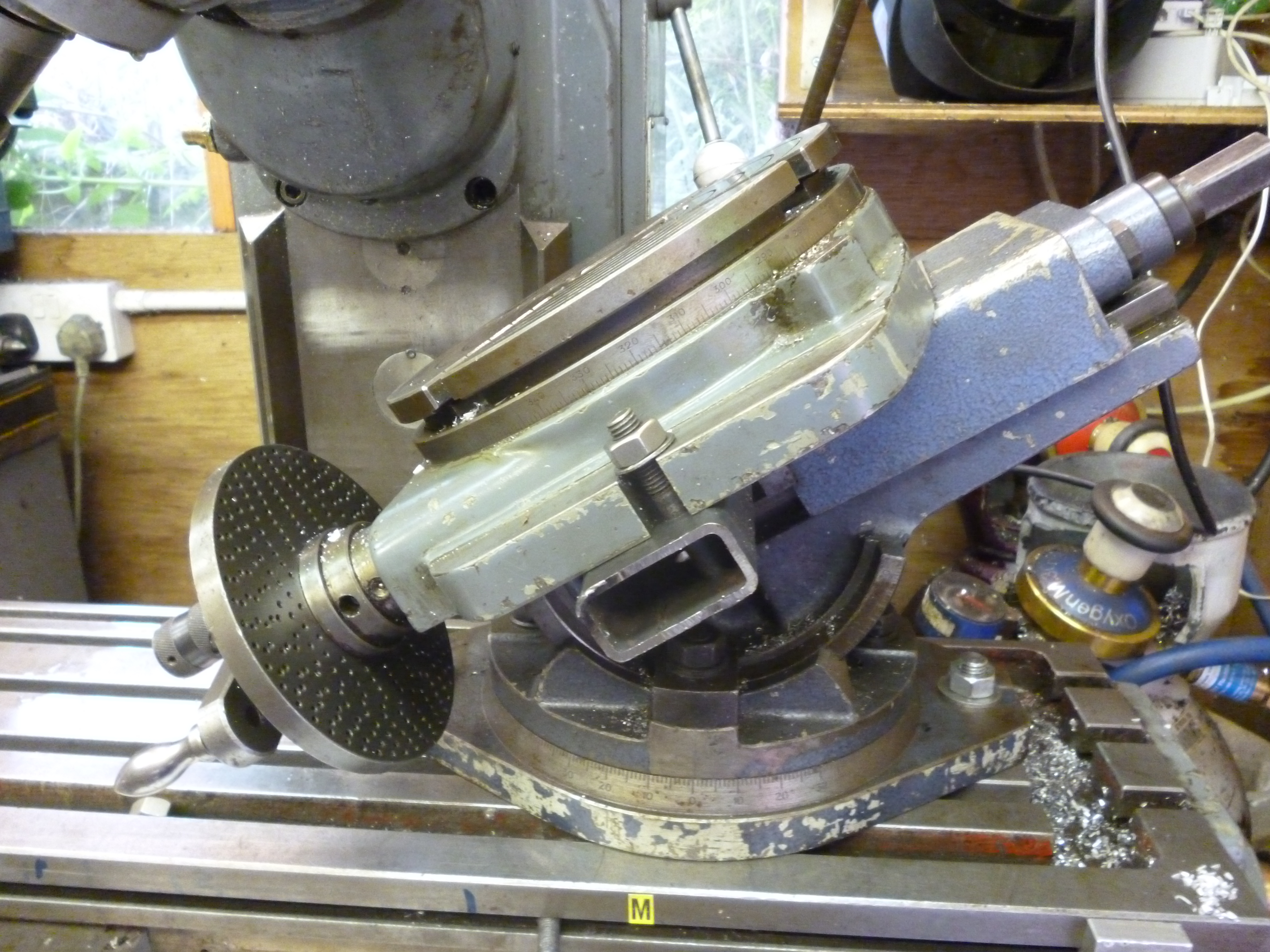
697 rotary table on tilting vice
Fig. rotary table on tilting vice 697
Rotary table clamped to tilting table
A tilting rotary table is much higher than a plain rotary table and also much heavier. Most of the time a rotary table is needed it is often horizontal. So when the rotary table is anywhere other than nearly vertical, the overall height can be a problem.
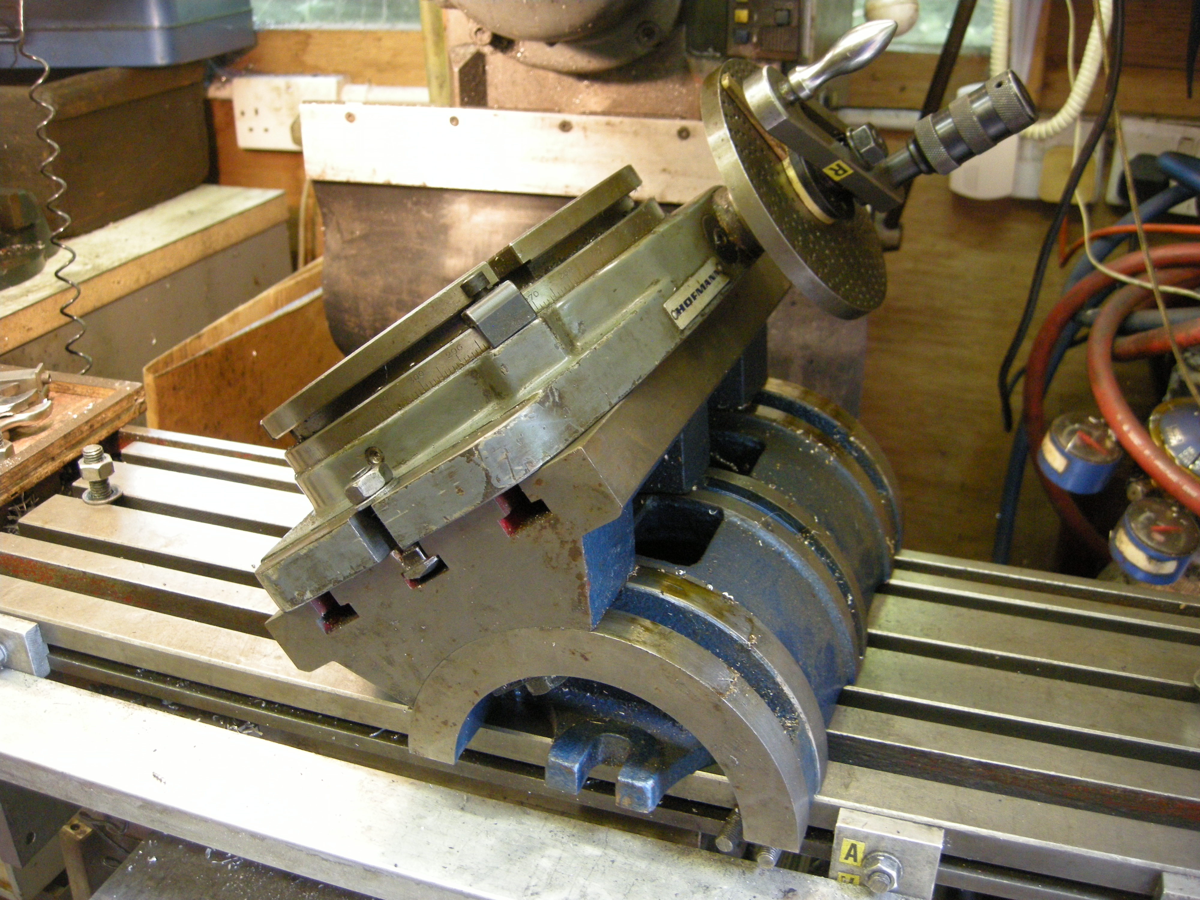
241 rotary table on tilting table
Fig. A rotary table on a tilting table 241
Notice that because the clamping slots for the tilting table are only at its ends it is only possible to use this one way round unless a sub-table is available to hold the tilting table the other way round.
Rotary table clamped to sine table
In this situation the sine table has the advantage of working where the tilting table does not.
The sine table does not have a height problem but on the other hand can only be used for shallow angles.
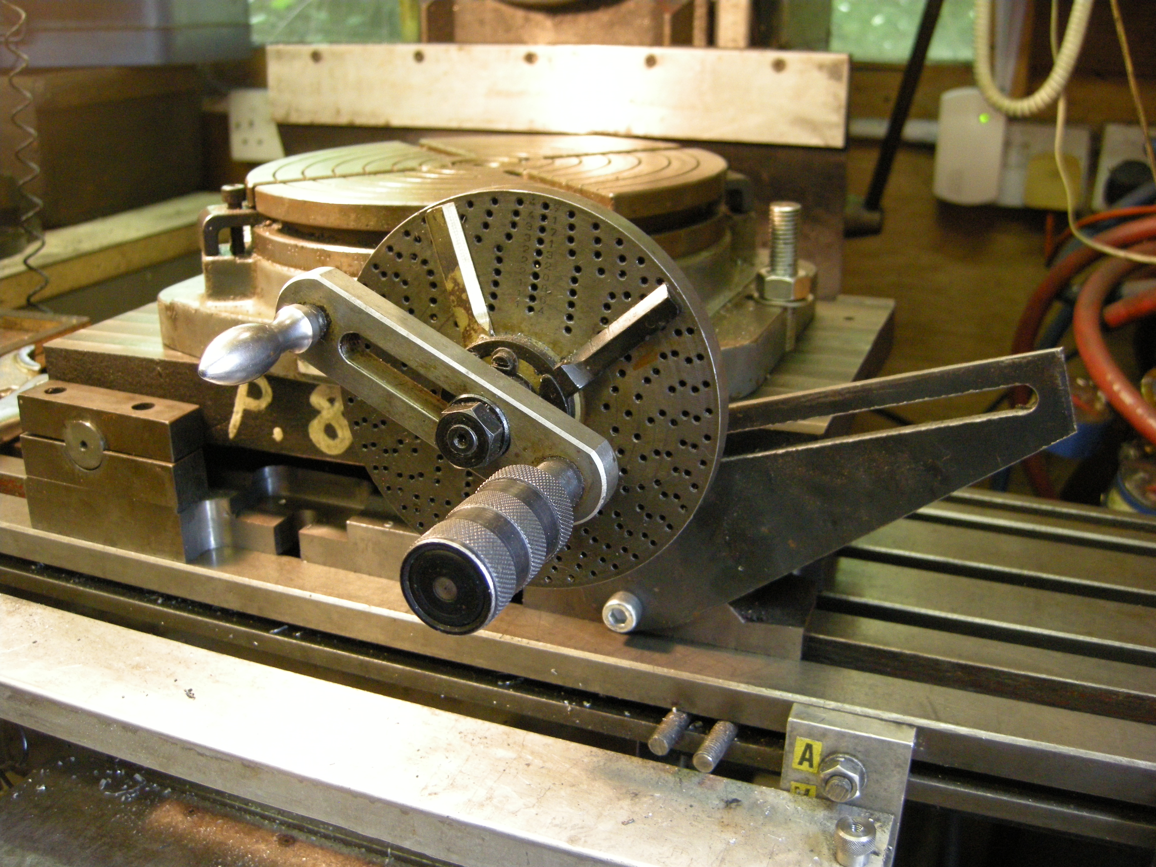
39 rotary table on sine table 2
Fig. rotary table on sine table 39
Second group – non-rotating rotary table with driven tilt
If the top rotary table is not required to be rotated whilst milling it can itself be simulated with an angle plate but the angle plate needs to be tilted whilst milling.
This seems to lead to just one combination. This is an angle plate mounted on a vertical rotary table.
Fig angle plate mounted on a vertically mounted rotary table
