Rotary table driven by the leadscrew
Suppose a rotary table is mounted on the milling table and the drive to the rotary table is driven from the leadscrew. As the milling table moves the rotary table will rotate by a certain angle for a certain movement of the milling table. The resulting shape will be an Archimedean screw so long as the center of the cutter lies on a line parallel to the x direction and passing through the center of the spiral.
But there is a serious problem. All rotary table have a built-in worm and wormwheel arrangement. This dramatically reduces the rate at which the rotary table can rotate. Furthermore, even if the worm could be disengaged from the wormwheel there is no way of driving the table round.
Suppose the gearing is 1:1 between the leadscrew and the rotary table and the pitch of the ledscrew is 5mm and the gearing on the rotary table is 60:1 then for a 5mm movement, the table will rotate by 6 degrees. To turn a whole circle the leadscrew will have to turn 60 times and will have moved 5 * 60mm, ie, 300mm.
Even if the gear train is used to speed things up the “pitch” of the spiral is limited. This means it is not possible to produce spirals like the one found on the scroll of a chuck.
Setting up the rotary table

1035 driving the rotary table 2
In this case the gear train has been set up using the parts that go with the dividing head.
To achieve this setup the handle, dividing plate and sector arms have been removed from the rotary table. The rotary table is too low so it has been mounted on the tilting table though this is setup for zero tilt.
The cutter is lined up as described above.
Making a heart shaped cam
However there are still uses for the spirals can be produced. One is for making cams. By definition a section of Archimedean screw will push a cam follower in a straight line at rate proportional to the angle it has turned through. This gives a “constant rise” cam. This surface can be on most of the cam or on only part of i
One interesting shape is a heart shaped cam
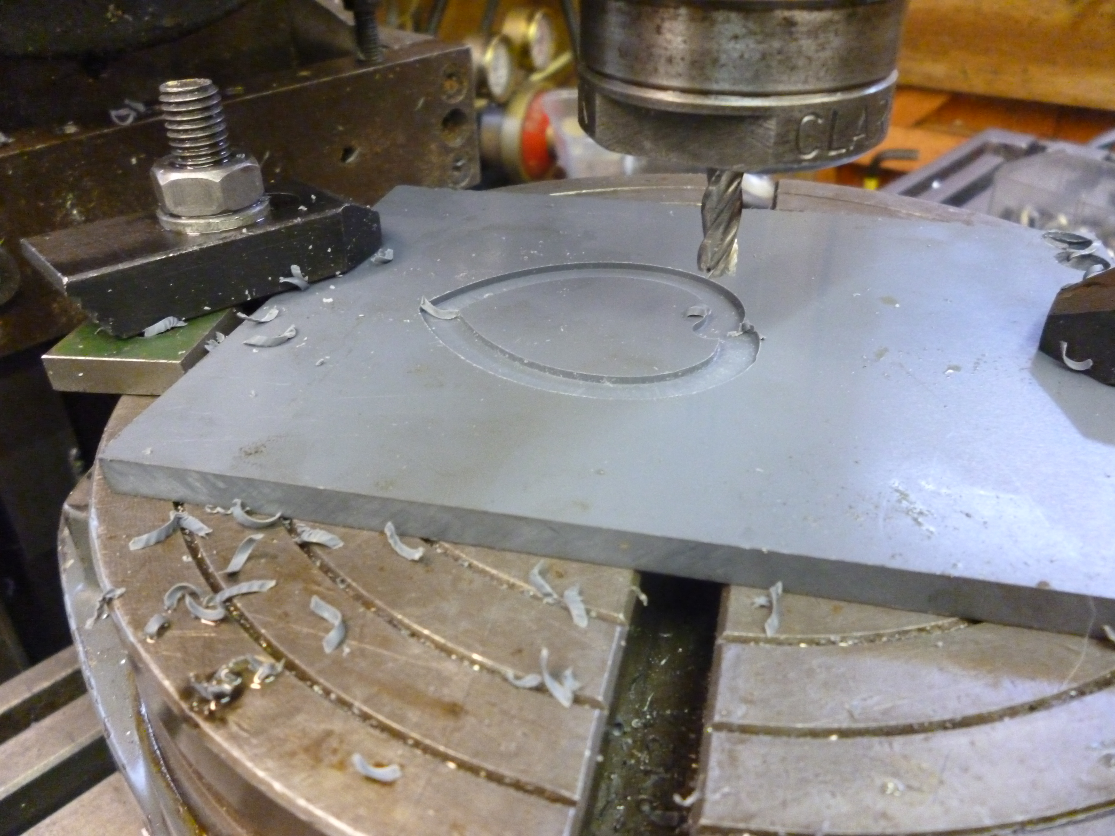
43 heart shaped cam
This is used where the cam follower has to move evenly from left to right and back again. This is achieved by reversing the direction of the gear train. however the backlash going one way will be different when going the other way. This means that after the first cut has been made the cutter is lifted or the table lowered, the table is run backwards and the start point reset after taking up the backlash. An example of this is found on sewing machines.
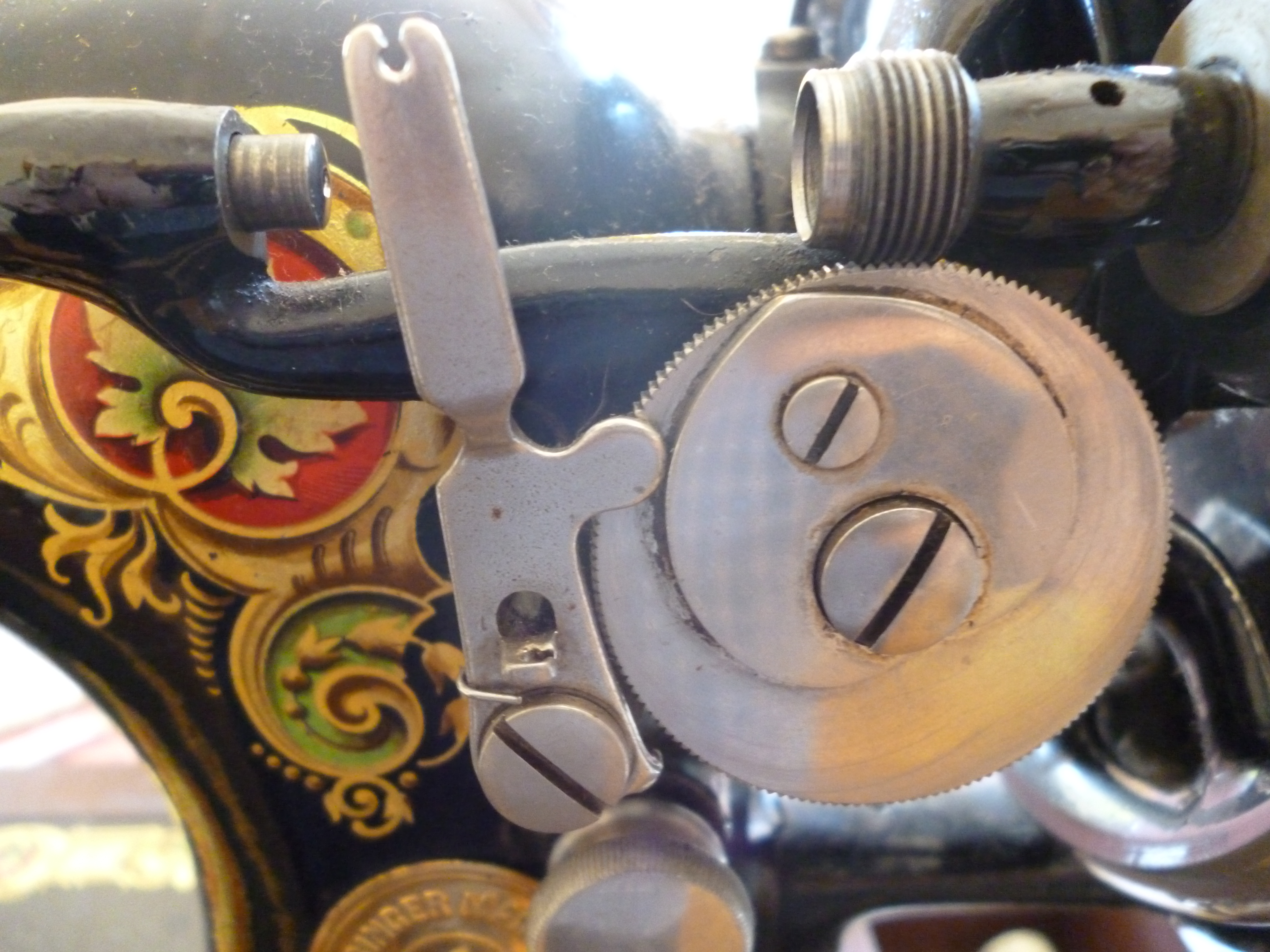
571 cam on sewing machine
Coarse and fine scrolls
The above works because if the pitch of the leadscrew is 5mm and the ratio of the worm/wormwheel is 40:1 then 10 tuns, for example, of the leadsacrew will move the table 50mm and will rotate it by 90º. For this to happen the gear is 1:1. This can be considered to be a coarse spiral suitable for cams etc.
Spirals on scroll chucks
Of course, a spiral could have a much finer spacing. A spiral like this is the basis of the scroll mechanism of any self-centering chuck. It is quite easy to see how, in principle this spiral works. But, making it is not as easy as one might imagine. The problem is because of the built in speed reduction due to the worm/wormwheel arrangement in the rotary table.
Suppose the pitch of the spiral required was 5mm and the pitch of the lead screw was 5mm then for one turn of the lead screw the feed to the rotary table must be 40 times faster to compensate for the worm/wormwheel. This would mean a gear train speeding up the feed from the leadscrew to the rotary table.
There are two serious difficulties here. Firstly we cannot do this becaue the force required on the leadscrew would be too great. Secondly we will have problem getting such a large ratio with the parts we might be able to borrow from any dividing head we have.
Making a gear train with a very large ratio
Making a gear train out of two gears would require, if the smallest is 20 toothed, another of 200 teeth – out of the question. Using two pairs of gears will require two ratios of about root(40), ie 6 or 7 to one twice over.The usual gear train parts will not work.
In the following example the gear train uses something like the quadrant arm of a dividing head but it is a bit longer. It also have a slot in it so it can take a fitting that allows the drive from the gear side to the table side.. It fits a boss on the end of the table leadscrew.
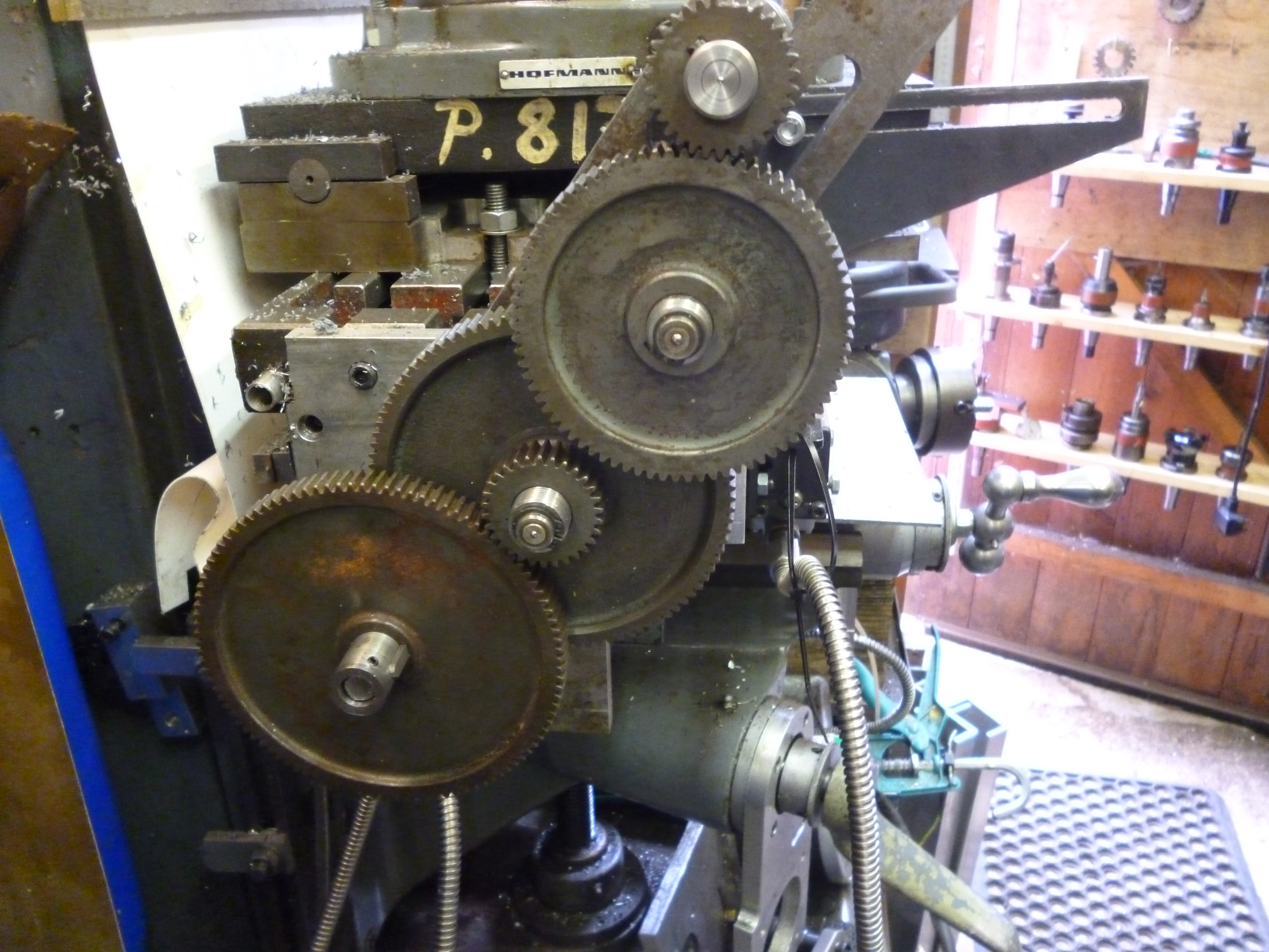
2322 spirals
fig 2322 gear train
The gears are probably off a Mikron gear hobber. These came in a set of gears from 20 teeth through to 120 teeth. They are slightly smaller than the gears of the dividing head. This is important since there is only enough space for six of these like this.
The real twist in this is how does the leadscrew drive a 1:40 gear train. Well, of course, it can’t. The trick is that the gear train is driven by hand at the input to the rotary table. Most people would fit a handle to do this.

2323 spirals
fig shaft from gear train to rotary table
What if the cutter is not aligned properly?
The center of the cutter must lie on a line parallel to the milling table which also passes through the center of the rotary table. The spiral will only be a true Archimidean spiral if this is true because the movement of the table will be directly proportional to the angle of the workpiece on the rotary table.
If the cutter is not aligned properly the pitch of the spiral will vary.

fig non-Archimedean spiral
The width of the cut is determined by the width of the cutter. The error can be seen as the variation in the width of the land between the turns of the spiral.
There could be occasions where this could be useful but working the precise nature of the spiral was slightly beyond me.
fig correct Archimidean spiral

There’s nothing like seeing something real to help to visualise an idea, thank you for taking the trouble to post
Thank you for letting me know you found something useful
john f