go to the home page
go to the page above this one – Milling – workholding – rotary table
Milling – workholding – rotary table with a three jaw chuck
Though the rotary table is very useful for holding flat workpieces it is not very good for holding rounds ones. By fitting a chuck onto it we can do all the things we have just seen that can be done with flat workpieces to round ones.
261 chuck on rotary table horiz
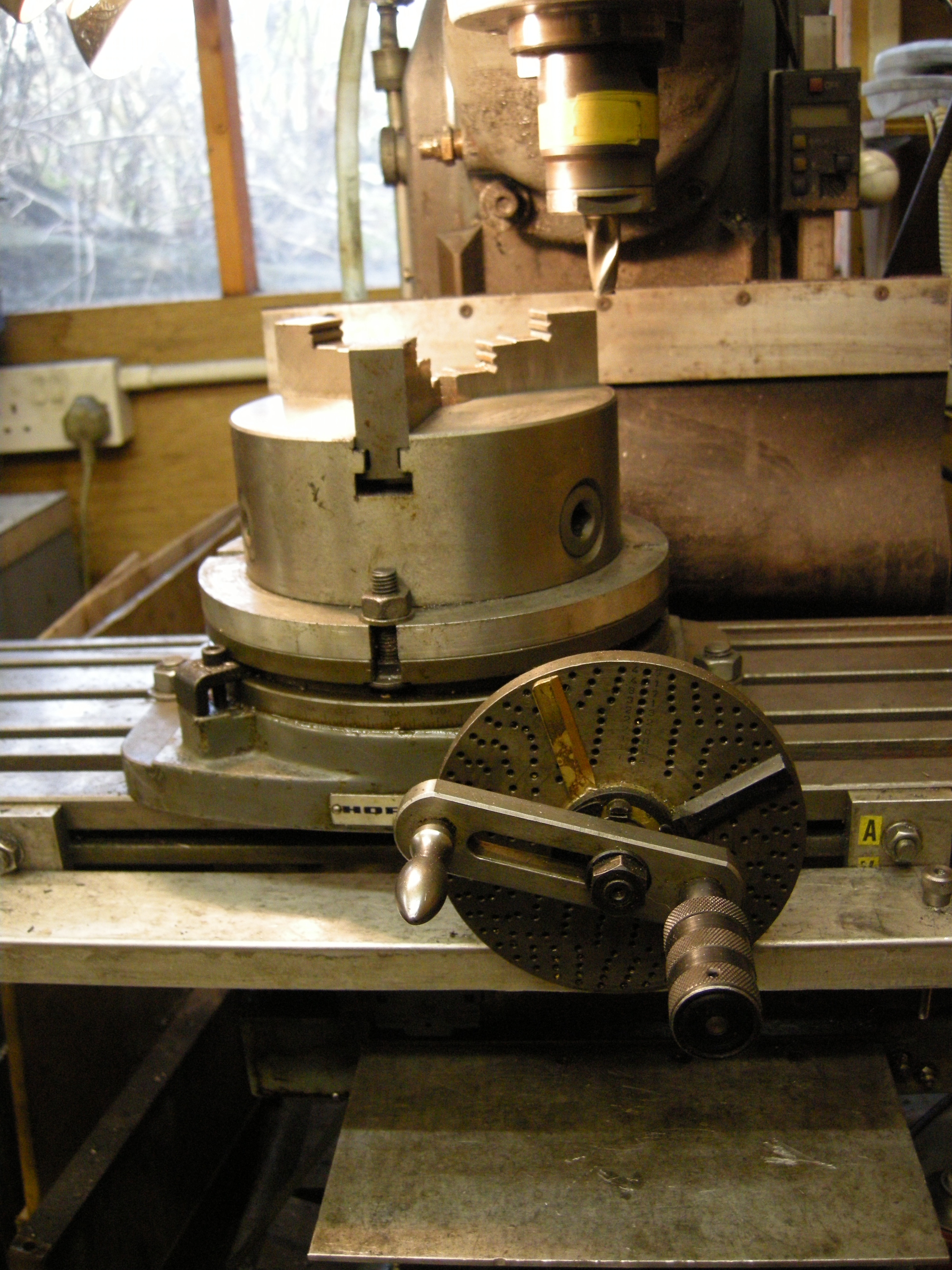
Fig. Rotary table horizontal with chuck 261
It is essential that the axis of the chuck is coaxial with the axis of the rotary table. The easiest way of doing this is to make a spigot. One end of the spigot fit the hole in the rotary table. The other end fits inot the hole in the back of the chuck.
see rotary table alignment – Fitting the chuck to the rotary table
Example – milling a part of a dog clutch
Dog clutches are frequently used on machinery. The same components are also used on handles for manually turning shafts.
264 dog clutch on lathe
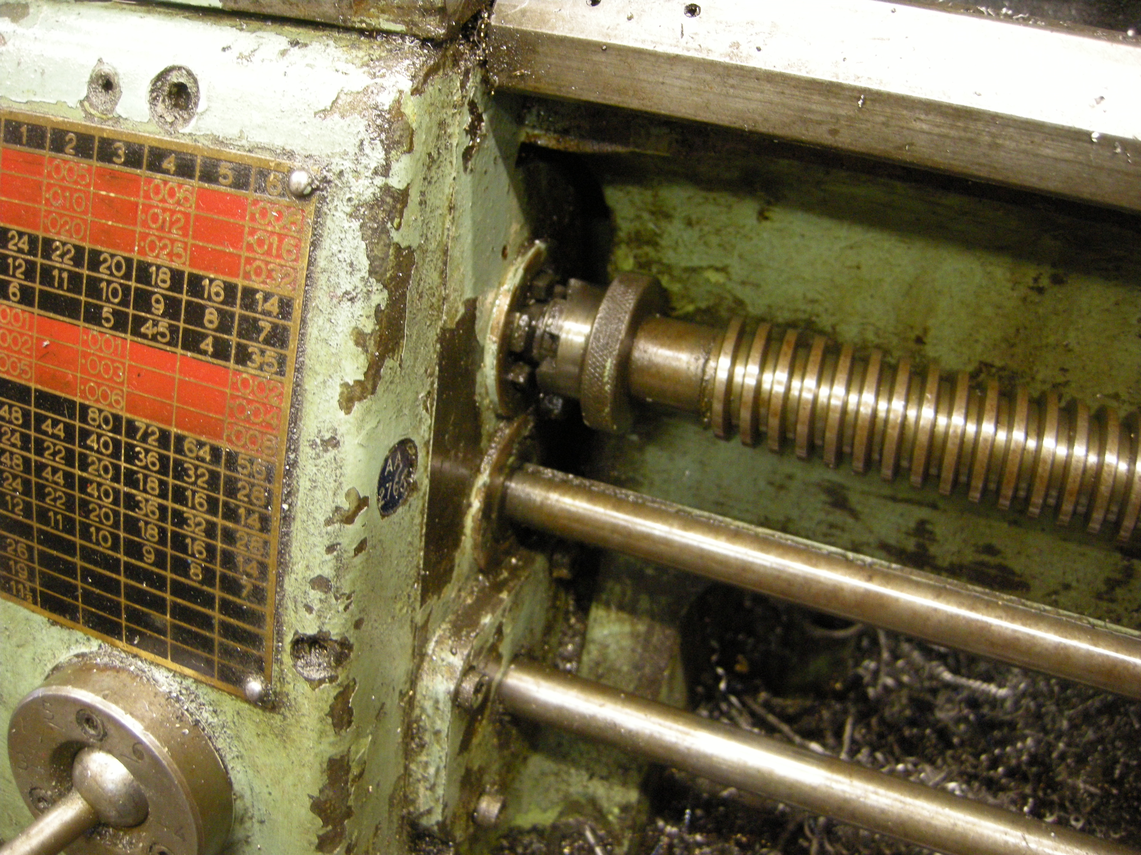
Fig. Dog clutch to disconnect leadscrew 264
The two parts of the clutch are identical.
It might seem, at first sight, that each part of the clutch should have an even number of teeth. But this makes making it rather complicated since each side of each tooth needs to be machined separately.
If the clutch has an odd number of teeth it turns out that in one cutting operation one side of the cutter can cut one side of one tooth and then the other side of the tooth on the other side of the clutch.
Fig. dog clutch with odd number of teeth – 1034/25
Fig. dog clutch with even number of teeth – 1035/27
Consider a dog clutch with five teeth. The angle between each cut is 360/5, that is, 72°. It might appear that three cuts will give 5 teeth but each tooth needs to be cut on both sides. So five cuts are needed. If we start with the workpiece at 0° then the cuts will be with the rotary table at 0°, 72°, 144°, 216° and 288°.
If the table is lined up so one side of the cutter passes exactly through the axis of rotation of the rotary table then the width of each tooth will equal the gap between each tooth. The edges of the teeth will all be radial.
If the center is offset then all of the teeth and all of the gaps are the same size but the size of the teeth will be different to the size of the gaps. Also the edges of the teeth will not be truly radial.
It might be possible to deliberately offset the workpiece pieces so all the teeth were slightly smaller than the gaps in the opposite part so as to provide a loose fit between the two parts.
This could be cut using either an endmill in the vertical mode or a side and face cutter in the horizontal mode.
See MEW 94 p53
331 machining a dog clutch 1
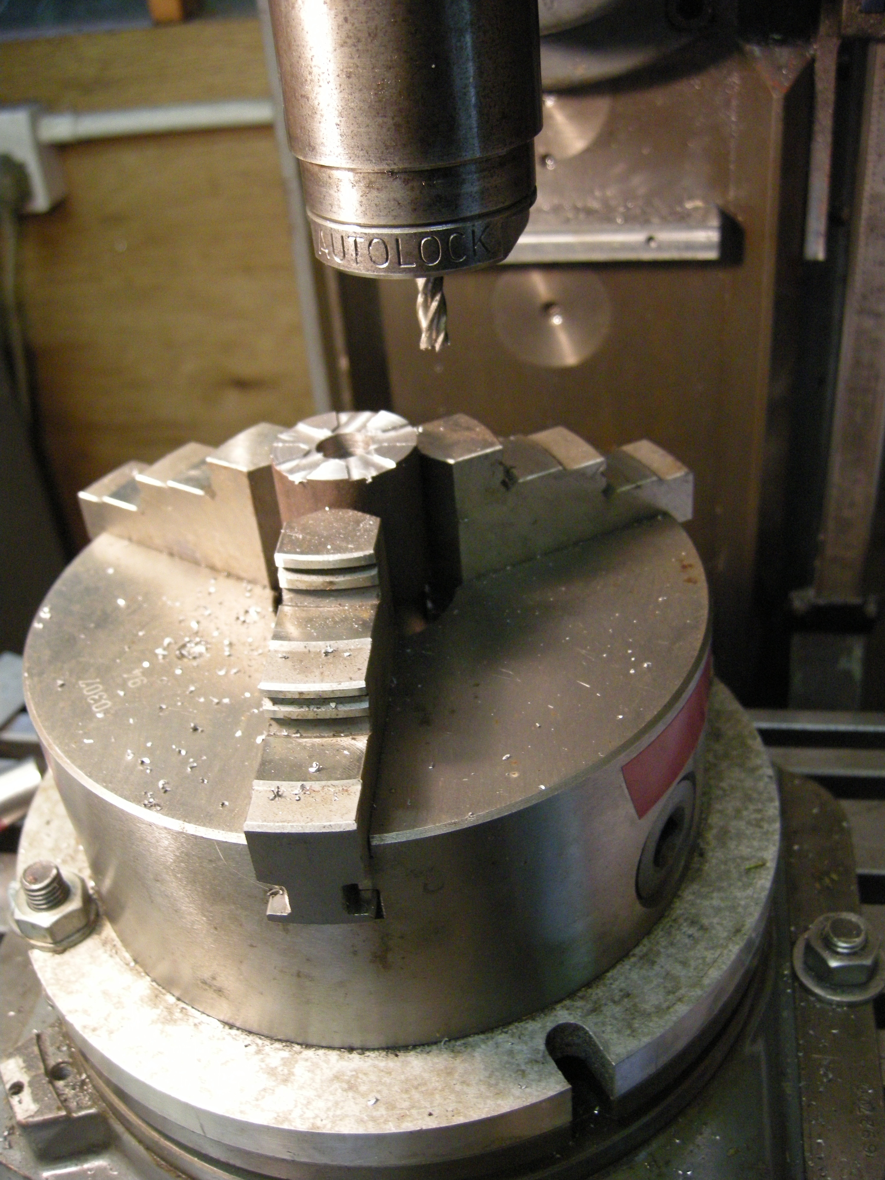
Fig. Making a dog clutch – vertical mode 331
434 machining dog clutch
Fig. Making a dog clutch horizontal mode 434
Rotary table horizontal with chuck – head tilted – vertical mode
If the cutter is a dovetail cutter this setup can be used to make saw toothed clutches. The same principle can be used to make hole cutters.
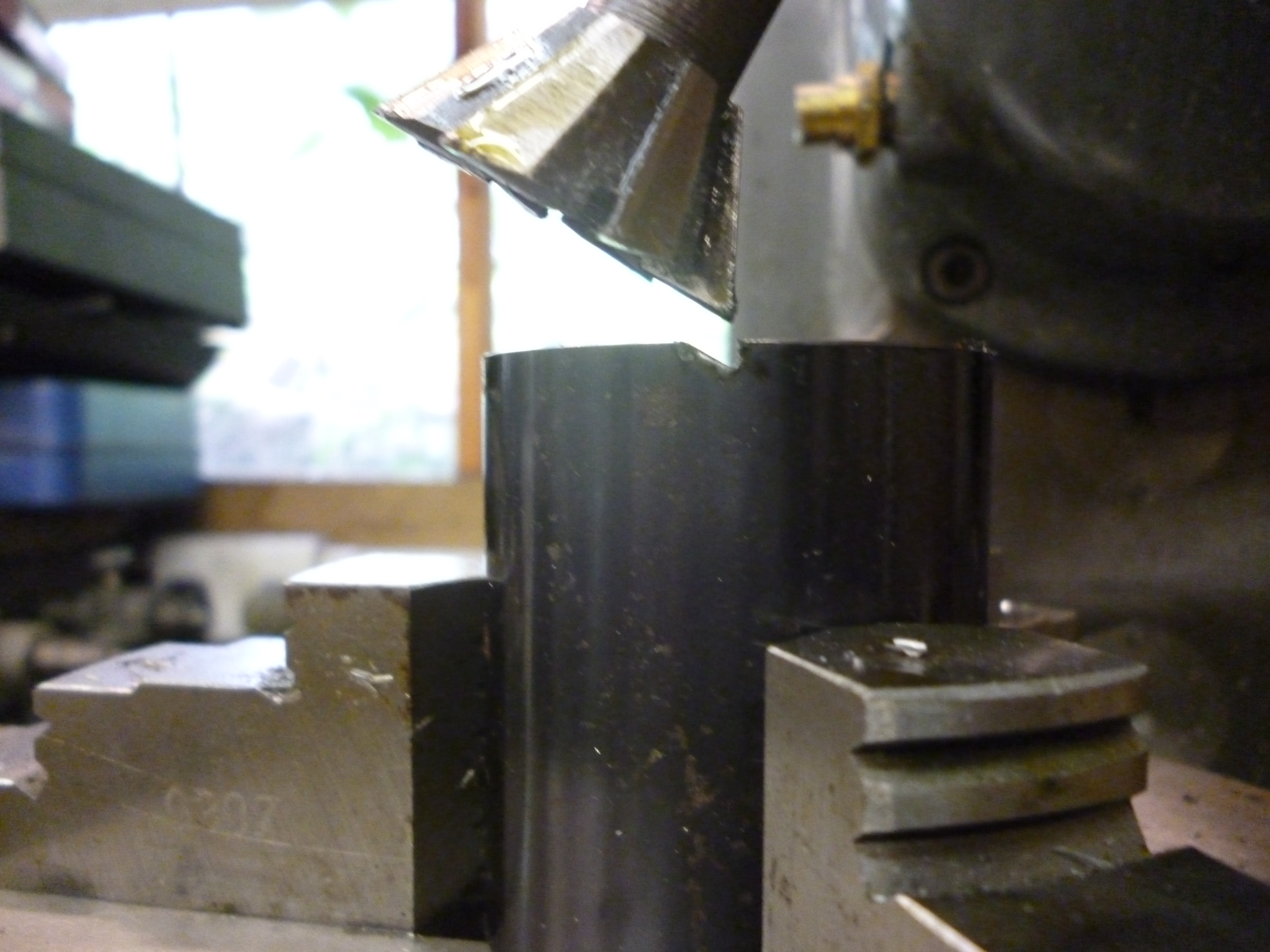
671 saw tooth clutch first cut
Fig. Making a sawtooth clutch – first cut 671
A 60° cutter will have to be tilted by 30° to give a vertical edge. The slope of the saw tooth will then also be 30°.
If a shallower slope is needed then the solution is to tilt the vertical head to a smaller angle and cut the sloping edges again with this setting.
672 saw tooth clutch second cut
Fig. Sawtooth clutch – second cut 672
If two parts are made like this the surfaces they will work but the surfaces do not make perfect contact. This could be done by using the method used for face gears but using a dovetail cutter as described here.
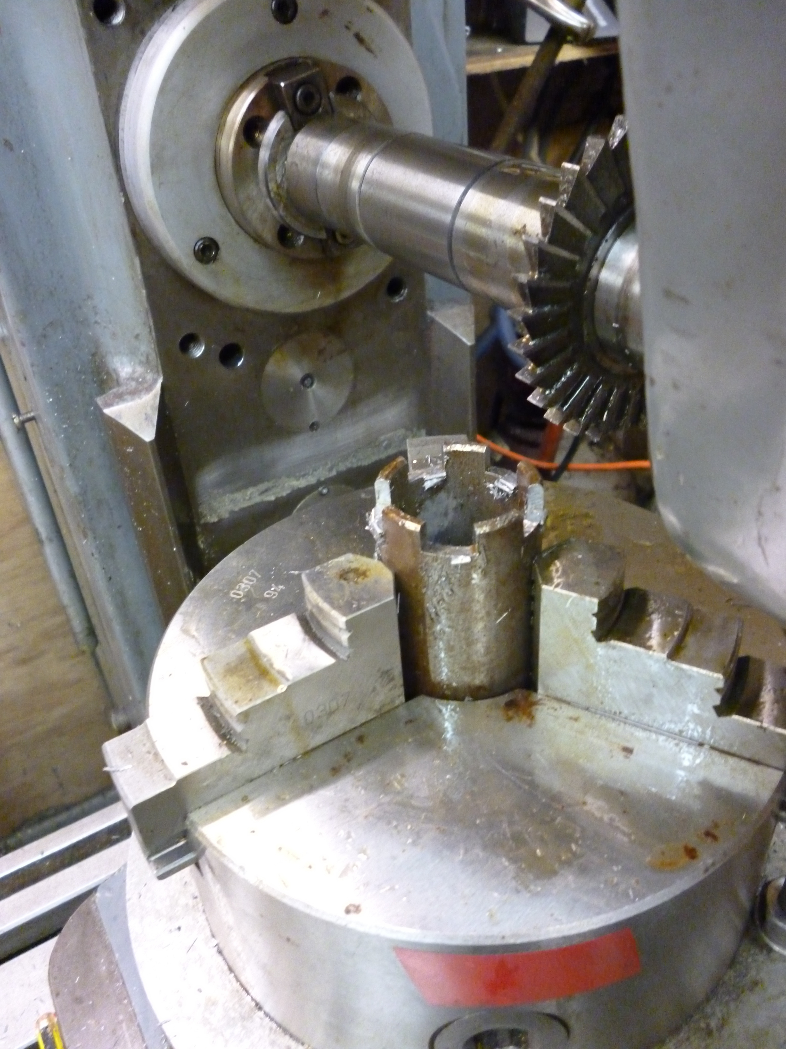
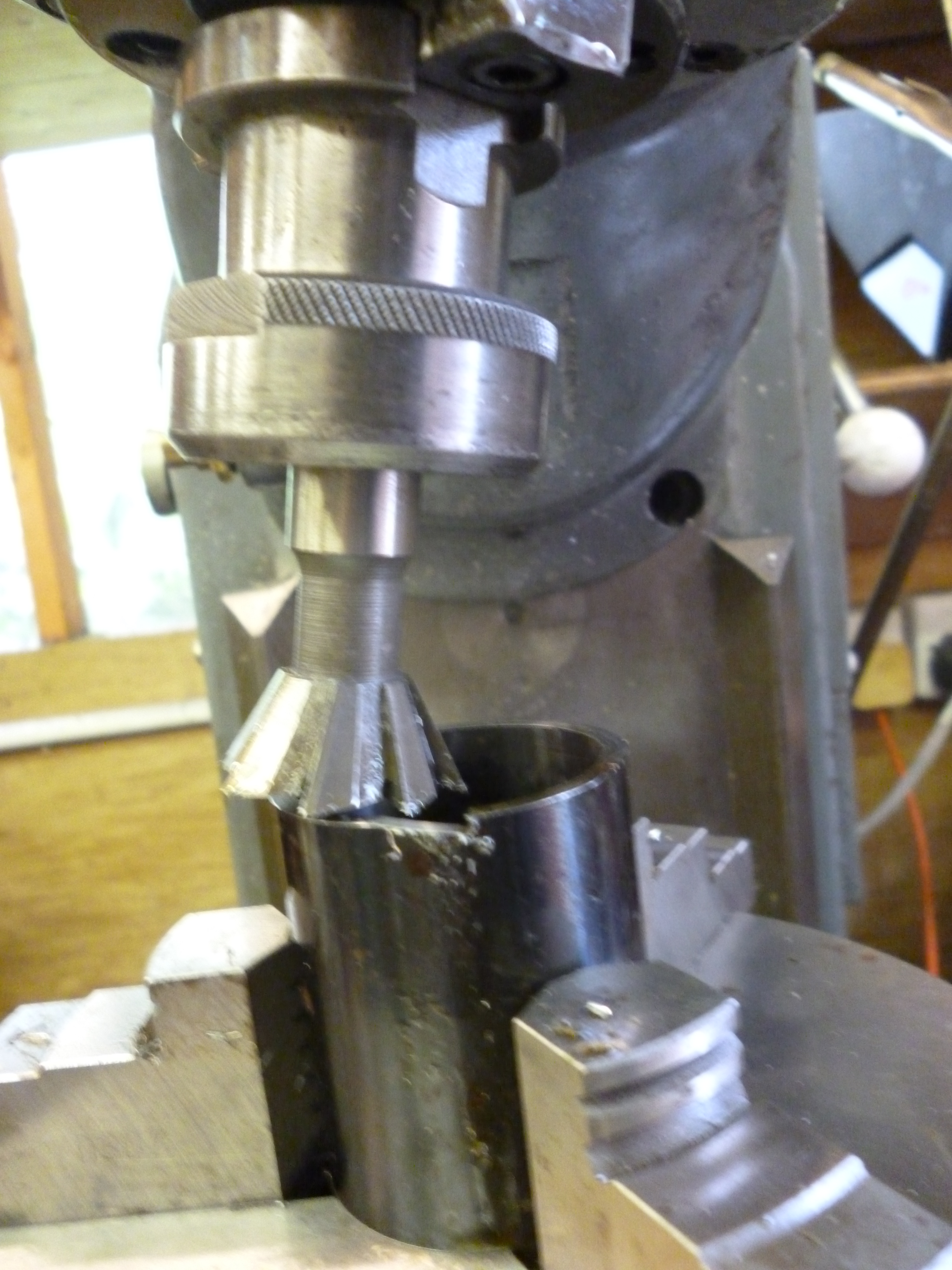
Making hole saws
To make a cutter the cutting surface needs rake and clearance. This is very similar to making a keyway broach except that, instead of moving linearly to cut the next tooth, the workpiece is rotated. And, of course, the finished workpiece needs to be hardened.
Rotary table horizontal with chuck – drilling – vertical mode
This is a very useful setup for drilling a circle of holes on a round workpiece.
Except in the simplest cases, it is essential to work out the angle for each hole before starting. If the rotary table/chuck combination is centered with the vertical spindle then the y axis should be locked. The milling table is moved by half of the pitch circle diameter. The y axis is then locked.
Example – cylinder cover
An example of this is on a cylinder cover. It is very seldom that a cylinder cover can simply have a ring of holes drilled in it. Very often the cover might not be a simple round shape but might have parts coming of it. The pattern of holes has to allow for this. This means that the cover has to be aligned before any drilling can be done.
Computing angles for left and right hand patterns
It is quite common for one workpiece to be machined with say, a pattern of holes going round it. We then need another piece machined with a mirror image of the holes of the first. It is best to work out what the necessary angles are in advance. This can be done using a spreadsheet. Notice we must start so a reference point on the workpiece is set to the 0º position on the rotary table.
Suppose the angle from 0º is in column 1, the angles for the first piece are in column 2, then the values for the mirror image are in column 3. The formula for the mirror image is the value for column 2 minus 360º.
A degs B degs C degs
These angles are, in fact, polar coordinates.
Drilling the holes
When drilling holes backlash is not important. All that matters is that the fiduciary mark reads the right angle for the current hole. When this is the case, regardless of how this position was reached, the rotary table should be locked before and during drilling.
Drill guide
If a large number of holes have to be center drilled and then drilled it is possible to speed up the process. If a drill guide is made then the holes can be drilled just with the drill all in one go.
The drill guide fits the milling table and provides a guide for the drill bit right next to the surface being drilled.
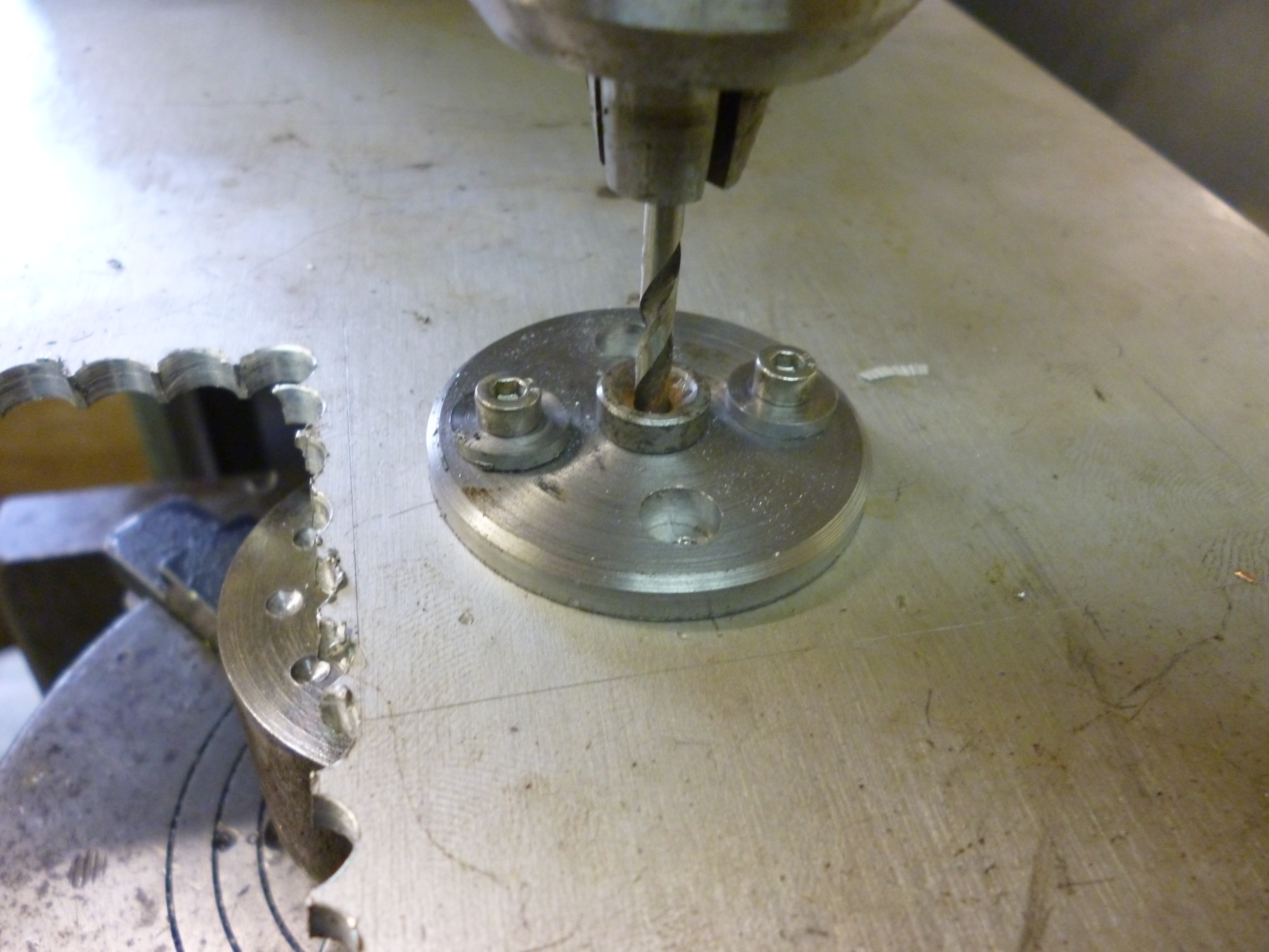
578 drill guide 2
Fig. Use of drill guide 578
The drill is held by a bush, preferably hardened, that is specially made to fit the size of the drill bit actually being used.
The holder for the bush is made so that if floats and is fixed after the drill has gone through the bush.
The whole plate is fixed to the same hardware used for fitting things to the column of the milling machine.
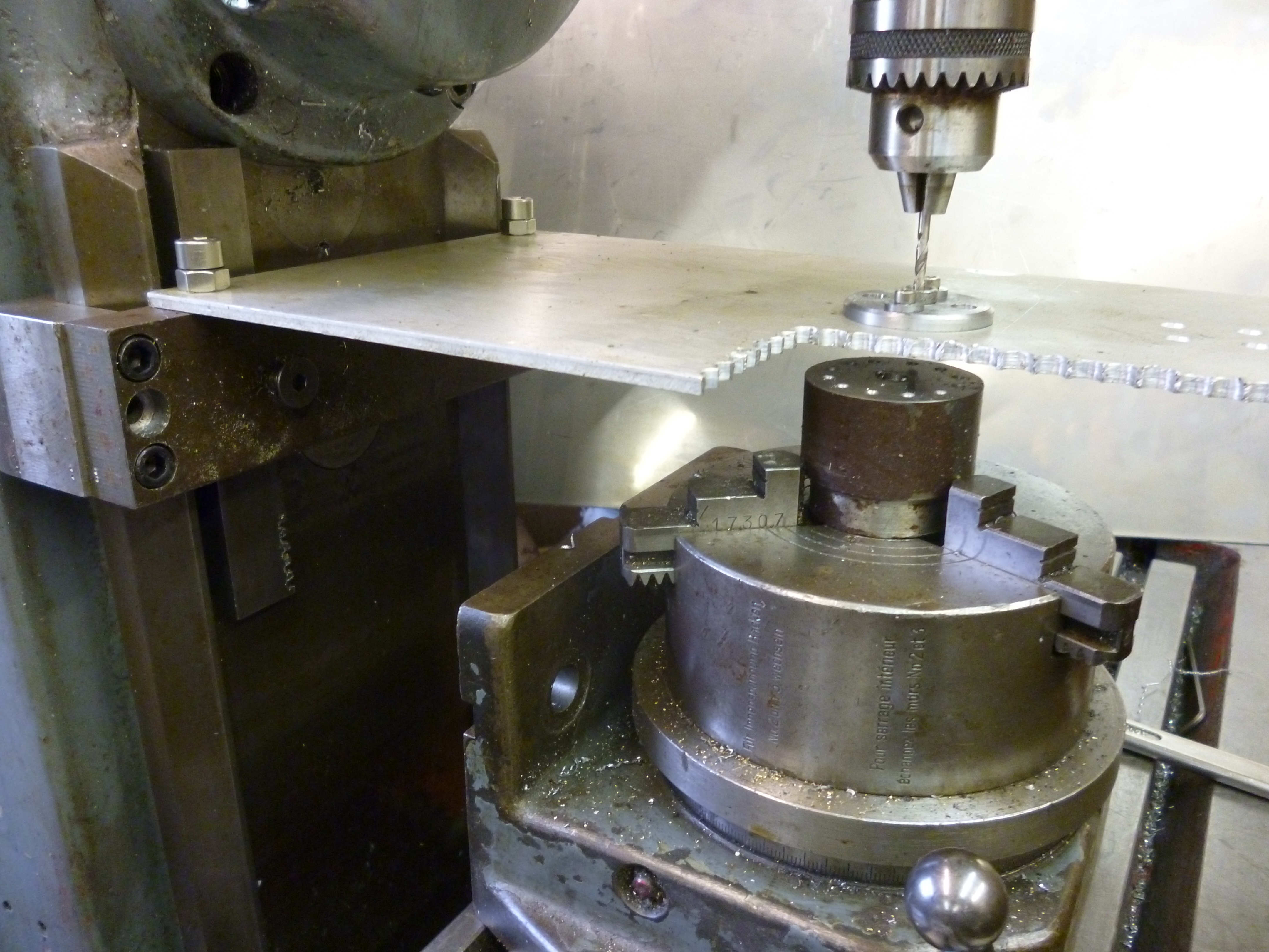
581 drill guide 1
Fig. Fixing to the column of the milling machine 581
Test of drilling holes in a circle
The assumption when drilling a circle of holes is that they are:
All the same distance from the center of the circle,
They are all the same angle apart from each other,
The holes are the right size and straight.
A simple test is to drill a circle of holes in one test piece and then, with the exact same setting, to drill another circle in another test piece.
If dowels are fitted to all of the holes in one test piece then the other test piece should fit on the first with the holes on one at every possible orientation to the holes on the other.
Rotary table horizontal with 4-jaw chuck
One problem of using a 3-jaw chuck is very often a cylinder cover may need a circle of holes but the cover itself is not round and cannot be held in a 3-jaw chuck. One solution to this is to use a 4-jaw chuck instead.
A very similar solution is to fit the rotary table with side clamps. These fit the T-slots on the rotary table. They can be slid to anywhere along the T-slot and then locked it this position. They also have a screw mechanism so they can grip a workpiece.
This has an advantage over using a chuck in that the height of the rotary table with side clamps is less than it would be with a 4-jaw chuck.

573 rotary table with side clamps
Fig. Rotary table with side clamps 573
