go to the home page
go to the page above this one
Rotary table vertical with chuck
This combination is extremely useful. It is equivalent to a dividing head with a chuck.
Firstly, the chuck has to be mounted on the rotary table.
If a tailstock is being used then the height of the axis of the chuck has to be the same height as the center on the tailstock. If the rotary table has the facility to be mounted vertically then the center height of the rotary table is fixed. If a chuck is mounted on it coaxially, then the center height of the chuck is also fixed.
see Setting the height of a chuck/rotary table on an angle plate
Alignment with the milling table
In most cases, but not all, the axis of the chuck has to be parallel to the milling table. Since the axis of the chuck is at right angle to the surface of rotary table if the is at right angles to the milling table this requirement is fulfilled.
Usually the axis of the chuck needs to be aligned with the axis of the vertical spindle:
see Alignment of rotary table vertical with chuck
If the workpiece is mounted in a chuck mounted on a rotary table which is vertical and a horizontal type cutting tool is mounted on a stub arbor in the vertical socket then this configuration is very similar to using a dividing head on a horizontal mill.
The main difference is that most rotary tables do not have the facility to use dividing plates. Otherwise this can be a substitute for a dividing head. In most cases the spacing’s are going to be so many degrees and in many cases minutes per step. The only way to do this is to use a spreadsheet to give and absolute angle for each cut.
This set-up can do many of the jobs that, under ideal conditions, would be done with a dividing head fitted with a chuck (which is covered later)
It cannot be used to hold a workpiece between centers.
It cannot be used to hold a tapered mandrel.
But it can hold a parallel arbor, which could hold a blank, which was to be cut to form a gear. But this would often need a tailstock to support the far end of the arbor.
It might also appear that it has the advantage that the center height above the milling table can almost be chosen to suit the user. But, of course, with most workpieces being round, as the height of the center rises the space between the center and the cutting tool above rapidly diminishes.
The center of the workpiece must be aligned with the spindle
For milling large tubes
This set-up can be used to machine the ends of boiler tubes. It can also be used to drill and bore holes in barrels to fit steam domes, cylinders etc.
fig machining large tubes
In some cases where a boiler barrel has many holes in it (e.g. Piddington’s Locomotion) on close inspection of the drawings it will be found that various fittings on the boiler barrel are not designed at certain heights from the base of the barrel, as shown on the drawings, but at angles going round the barrel. This set-up is ideal for machining these. Redraw the boiler barrel drawing on a drawing with distance along the barrel one way and angles round from a datum the other way.
When the workpiece needs to be rotated by various angles the use of a rotary table, graduated in degrees, is actually an advantage over a dividing head.
There are two problems here; firstly because of the length of the barrel it is essential that the tube is supported at the far end. Secondly because copper is soft if the jaws hold the tube too tightly it is quite easy for them to distort the shape of the tube. With a large diameter tube there might not be space to use a boring head to machine the large holes.
The steady
The solution to the first problem is the steady. In the fig. is a steady that is bolted to the milling table.
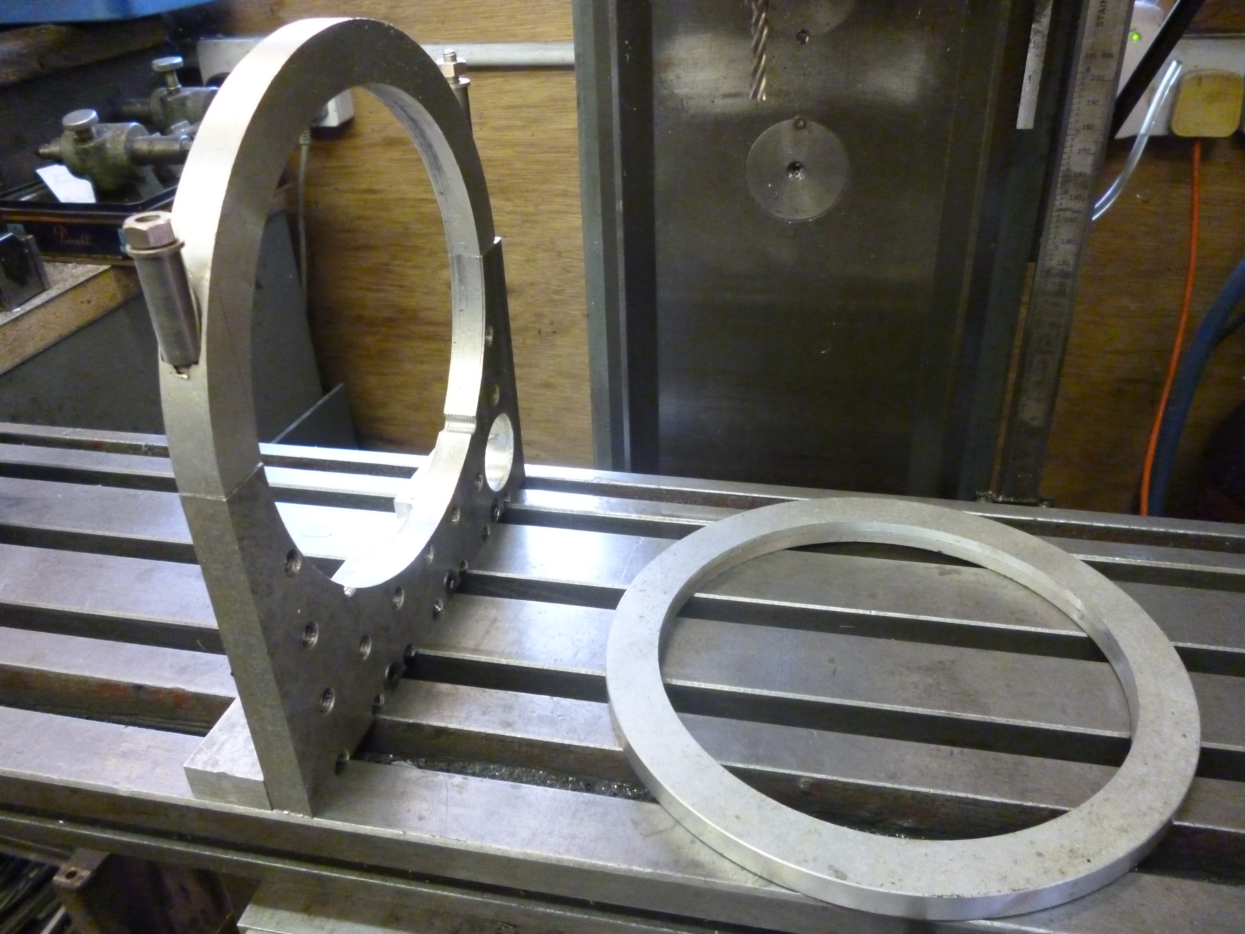
566 milling steady
Fig. Milling steady and ring 566
The size is adjustable not by arms as on a lathe steady but by rings made to fit the diameter of the tube being machined. This has the merit of holding the tube tightly but with even pressure all the way round.
The height of the center of the steady has to be the same as the center height of the chuck. Since the height of the center of the steady is fixed, the height of the center of the chuck has to be set to the same height.
The ring
The second problem can be solved in either of two ways at the chuck end. Either the tube is held using the outside edges of the inside jaws. In this case a ring is needed to fit round the tube to stop it being distorted. Or it can be held on the inside edges of the inside jaws or inside edges of the outside jaws by making a steel ring that fits round the tube. This has a slit in it so as the chuck is tightened it tightens up on the tube – evenly.
The “spider”
A spider is a device that fits into the end of a large diameter tube. The center of the spider has a center drilled in it. This can be used, with a tailstock, to support the end of the tube whilst milling it.
This does mean that the center height is limited to that of whatever tailstocks are available.
Fig. – spider
