go to the page above this one “helical milling”
Various setups to get any necessary lead when using a dividing head
Definitions
When helical milling the dividing head is connected to the leadscrew so that as the leadscrew turns the milling table moves left to right or v v. The distance the milling table moves in the time it takes for the dividing head to rotate one is the lead. The lead is independent of the diameter of the workpiece. But, for a given lead, the helix angle will depend on not only the lead but the diameter of the workpiece.
Just three of the setups described below will easily give leads from 1000mm down to 1mm.
In all of this page it is assumed that the dividing head has a ratio between its worm and wormwheel of 40:1
I order to simplify thing I am assuming that all trains of gears are driven so the input is turning faster than the output. The merit of this is that, in general it is always possible to drive something, such as a dividing head if the gearing is such that it is going slower than the thing that is driving it. This is often not true the other way round.
The variables that are available to us are:
the pitch of the leadscrew L
the shaft of the dividing head D
the auxiliary input to the dividing head A
ratio on the gear train R
The lead screw has a pitch P which is either so many millimeters or so many turns per inch
There is an inbuilt division of 40:1 between the shaft driving the worm and the wormwheel on the main shaft.
Any gear train is shown by a box with an arrow in it. The arrow goes from the fast input to the slower output.
In all cases when the power is coming from the leadscrew it can be powered, usually at the opposite end by a motor or by hand.
The auxiliary input to the dividing head goes through a series of gears and drives the division plate round. It will only do this if the pin is engaged and the division plate is not locked. The gear ratio here is 1:1. The division plate will then only drive the main spindle if the worm and wormwheel are engaged and the pin on the handle is in a hole on the division plate.
This means that there are two ways the auxiliary input can be disconnected from the main shaft. Firstly, the pin on the handle can be pulled out. In this case the handle will turn and so will the main shaft. Secondly, the worm shaft can be disengaged from the main shaft.
It is possible to have a gear train that increases the speed at which the dividing head rotates but this becomes limited due to the strain on the gears.
Usually, whatever is being driven, is being rotated more slowly than whatever is driving it. For example, if there is some sort of feed mechanism to the leadscrew of the milling table then this is driven from a motor/gear box arrangement. If there is a dividing head and this is being driven from the leadscrew then gearing is always “downwards”, or going more slowly.
If the drive can be applied to the leadscrew then a motor can be used to drive it. If the drive comes from the handle of the dividing head then it has to be driven by hand from the dividing head.
notation
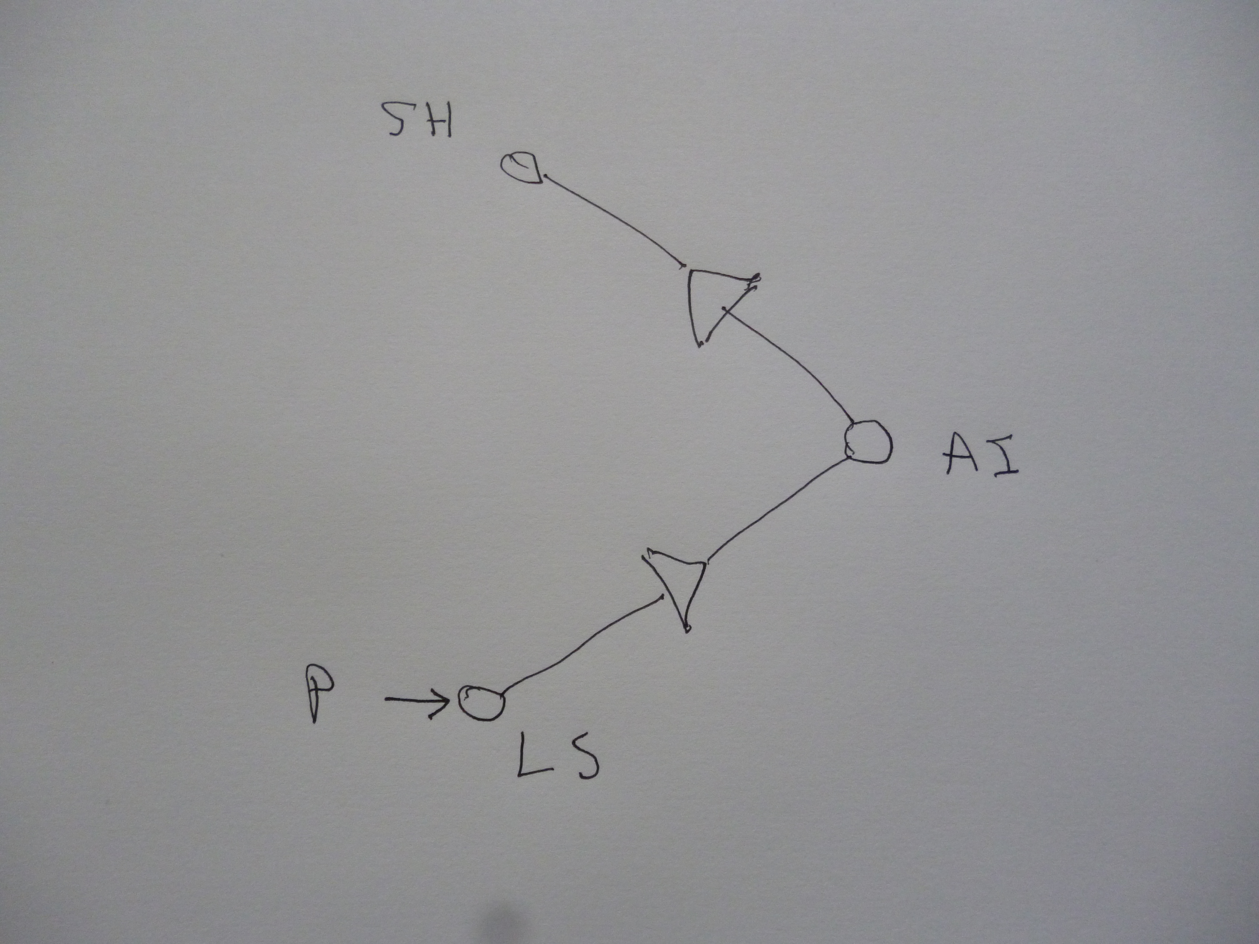
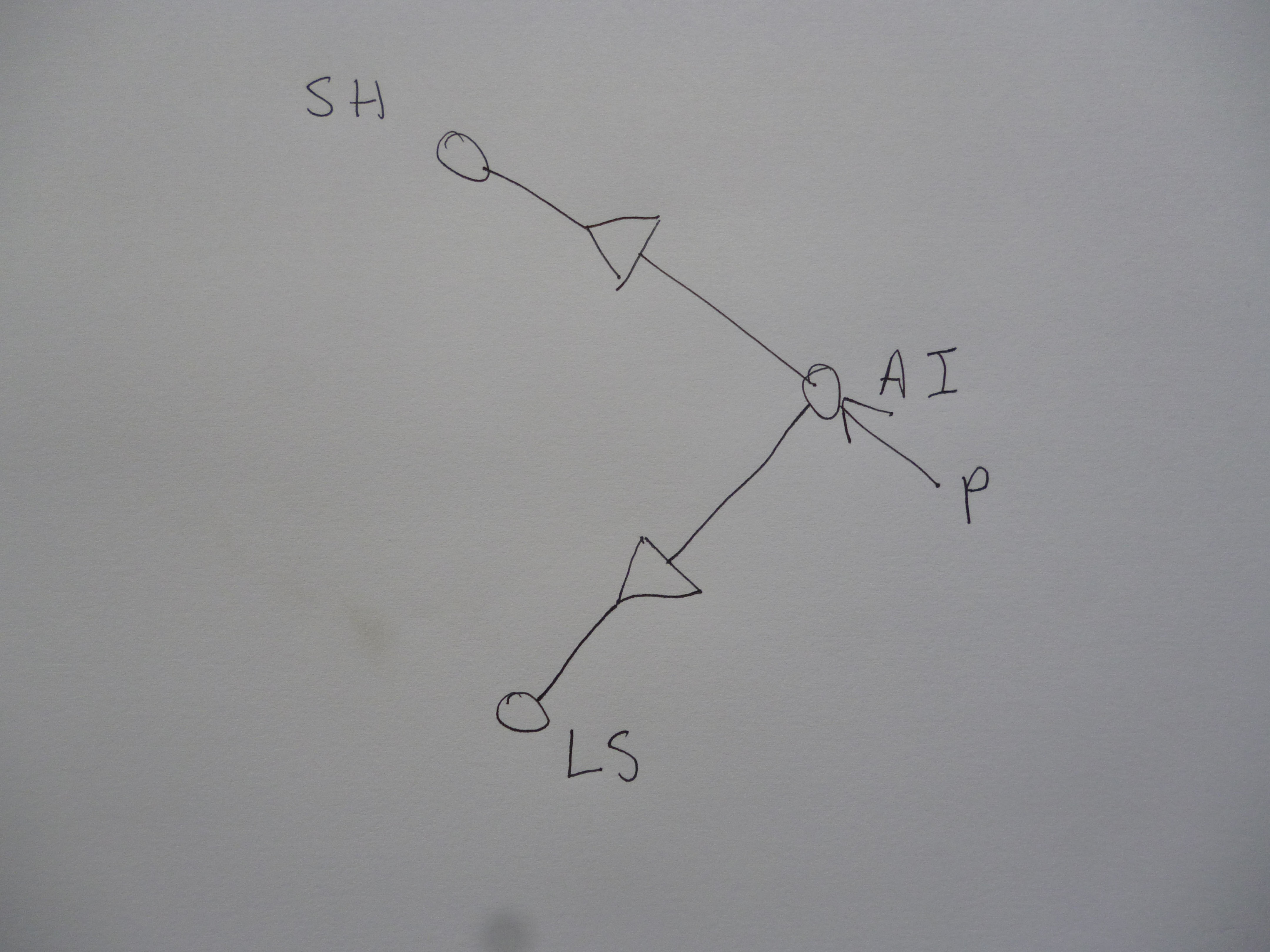
In the following diagrams
SH is the main shaft of the dividing head
LS is the leadscrew
Where power is applied to the leadscrew it can be done either by hand or by a motor/gearbox. It can also be applied at either end of the leadscrew.
AI is the auxiliary input
P is the point where the power is being applied
// the drive is disconnected at this point
Gear trains are shown by triangles. The triangle shows which way the power is going. It is assumed that the speed is always being reduced or nearly so.
G1 gearbox 1 – this is the worm/wormwheel arrangement in the dividing head
Because it is a worm and wormwheel it can only be driven one way.
This is usually fixed at 40:1 in industrial dividing heads
G2 this is gearing provide by the user.
It is not possible to drive the shaft if the leadscrew is engaged .
If the leadscrew is disengaged the auxiliary input is disconnected from the shaft with the dividing plate on it. So, in this case, it is not possible to use the handle on the dividing head to drive the auxiliary input
The first setup
The standard setup for helical milling is as shown:
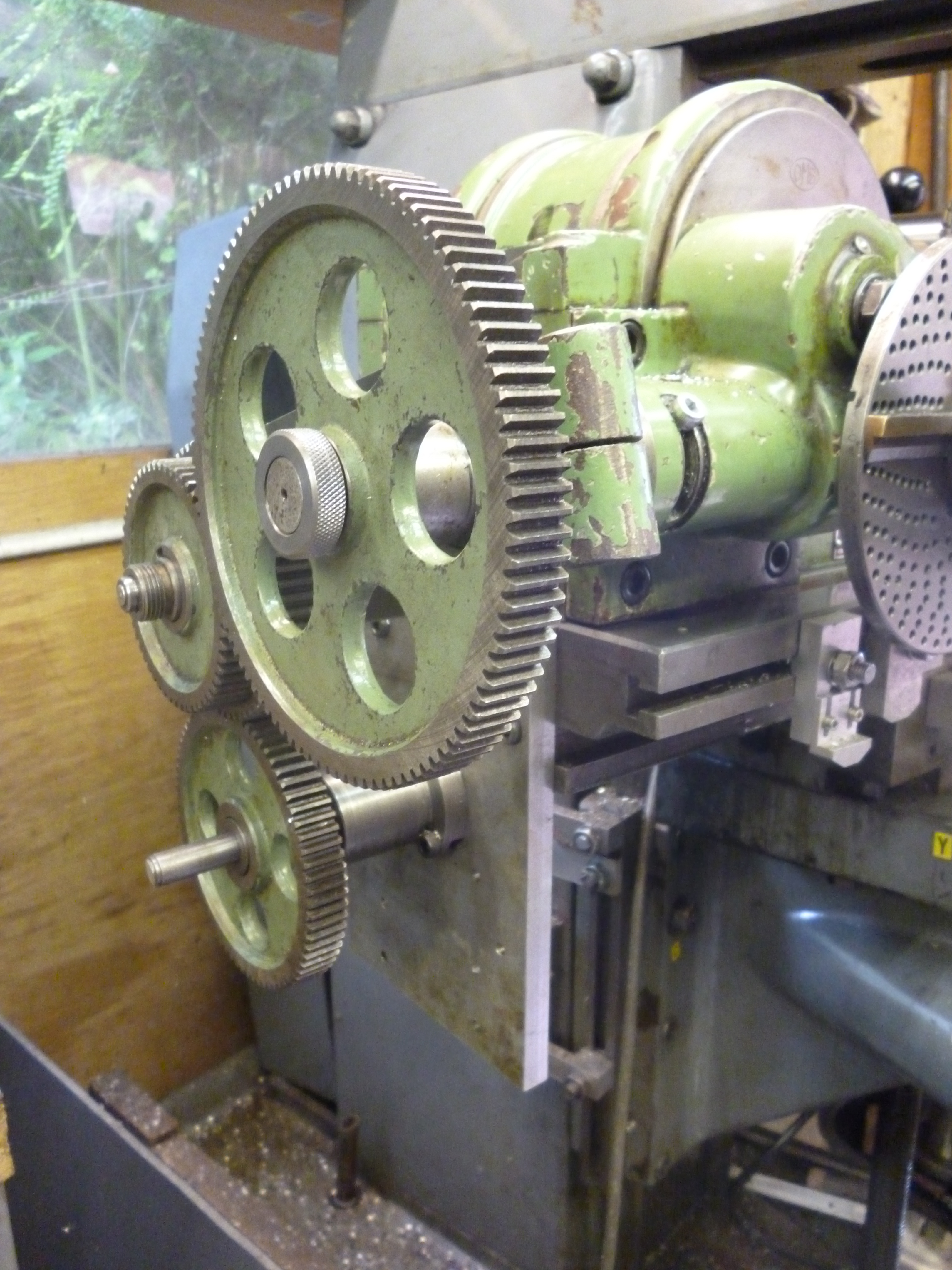
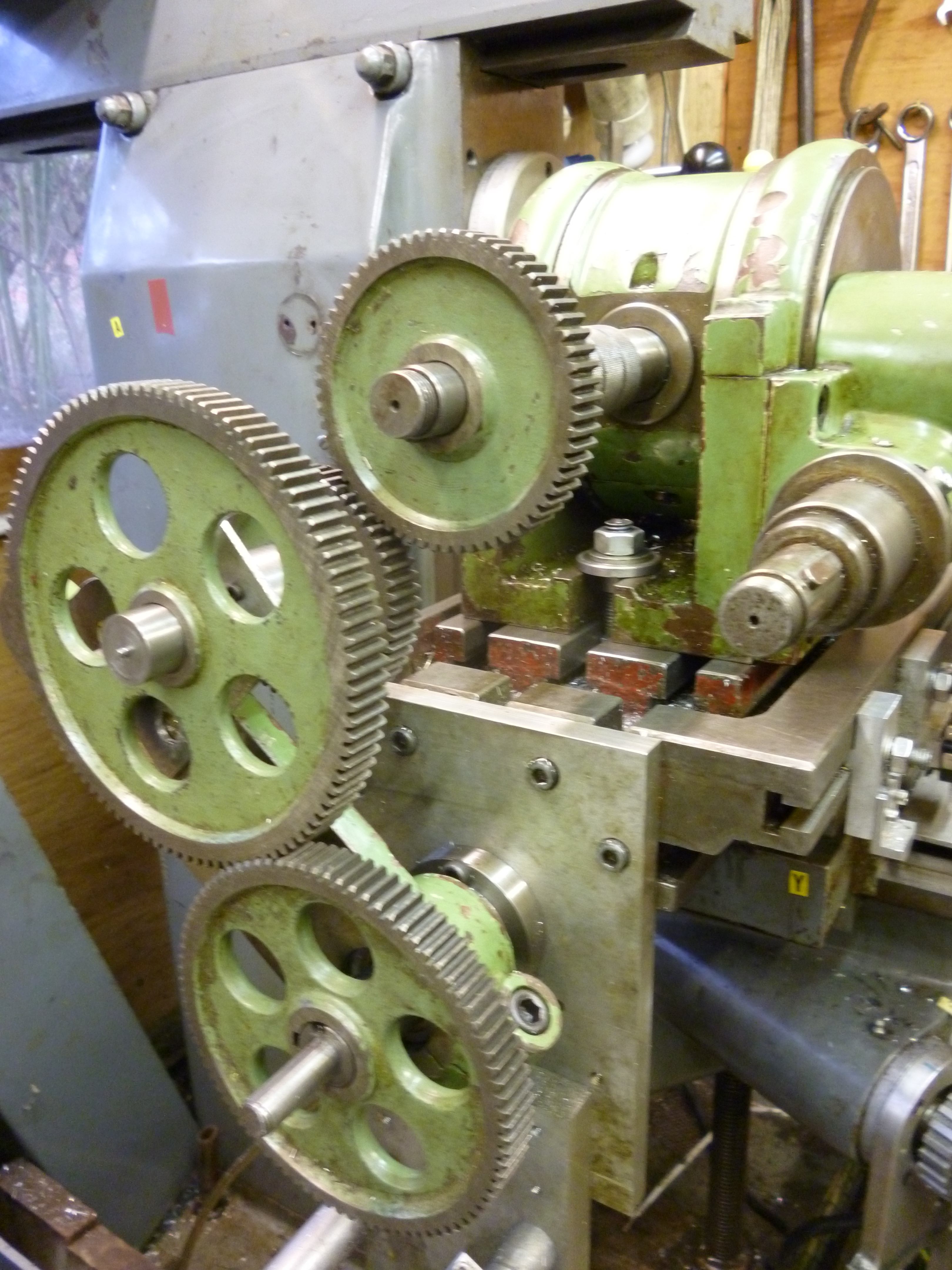
709 gear train fitted for helical milling
fig
4600 leadscrew driving shaft
The leadscrew goes into a gear train mounted on the quadrant arm and finally drives the auxiliary input on the dividing head.
One turn of the leadscrew is divided by the gear train ratio and then by 40
If the gear train is 1:1 and the leadscrew pitch is 5mm then one turn would move the workpiece by the distance 5mm:
Forty turns of the leadscrew would turn the workpiece through 360º and the lead would be 5mm * 40 ie 200mm
With a gear ratio of 1:1 the lead will be 200mm. As the gear ratio goes up to, say, 5:1 then the lead will be 1000mm.
Power feed can be used with this.
It would appear that this covers all of the longest leads that might ever be needed.
The second setup
If the dividing head is setup as above, ie, the auxiliary input is driving the main shaft when the handle turns. This can be turned round the other way. That is, a gear train goes from the auxiliary input to the leadscrew then the handle can be used to drive the main shaft with a reduction of 40:1 and drive the leadscrew with and reduction less than 1:1
Fig. Auxiliary input driving the leadscrew 462
4601 Auxiliary input driving the leadscrew
Fig. leadscrew driven by auxiliary input – 1012
With a gear ratio of 1:1 the lead will be 200mm. With a gear ratio of 1:5 the lead will be 40mm.
Power feed cannot be used with this.
The third setup
In the third setup the worm and wormwheel are disengaged. The main shaft has a handle on it and then goes through a gear box to drive the leadscrew.
fig 3
With a ratio of 1:1 one turn of the shaft will mean one turn of the leadscrew and a lead of 5mm.
With a ratio of 5:1 one turn of the shaft will mean 1/5 of a turn of the leadscrew and will give a lead of 1mm.
In practice, a more useful way of doing this is shown below
fig
In this case the gear is engaged but this gearing makes no difference, this is simply done so the user can use the existing handle on the dividing head
Power feed cannot be used with this.
There is an example of this being used in “Making flexible beam couplers”.
The fourth setup
In the fourth setup the worm and wormwheel are disengaged. The power is applied to the leadscrew. The lead screw drives a gear train that drives the shaft of the dividing head.
463 leadscrew driving dh shaft directly 1
Fig. Leadscrew driving the shaft directly 463
With a gear ratio of 1:1 one turn of the leadscrew will turn the workpiece through 360º and will produce a lead of 5mm.
with a ratio of 1:0.1 there will be a lead of 50mm.
Power feed can be used with this.

Hello John, I bought a similar dividing head with the shaft for direct dividing already inserted (like the fourth setup). I have no way of taking the shaft out, so I was wondering how these are attached. Is it screwed or a taper?
Can you send me a photo?
to johnsf23@hotmail.com
john
Sorry about the delay
This auxiliary shaft scews into the back end of the main shaft. On mine when it is screwed in then there is a small hole where, to the eye, one shaft meets the other a screw fits in and locks the two together.
hope this helps
john f