Back to home page
back to page above
The dividing head – introduction
The dividing head is essentially a horizontal (though sometimes tiltable) shaft with a wormwheel on it that can be driven round by means of a worm. The shaft has various means of holding a workpiece.
This may seem very similar to a rotary table. It is different in that there is no table to mount the workpiece on. Instead it is possible to mount a center in the shaft or mount a chuck onto it. Usually dividing heads are supplied with a tailstock. This is essential when using a center with the dividing head. It can also be very useful for supporting the workpiece when using the chuck. Most professional dividing heads, regardless of size, usually have a ratio of 40:1 between turning the handle and the shaft rotating. Strangely, smaller ones often have higher ratios, often 90:1.
On all dividing heads the worm is turned by means of a handle. Each turn of the handle can be divided by means of a dividing plate that contains a number of rings each with a different number of holes in it. The handle has a pin that can be moved to fit the holes in any one of the rings of holes.
Dividing heads can be split into three types. These are closely related to their size and complexity. These are the “plain”, the semi-universal and the universal. There is also a rather rare type that swivels in the horizontal plane.
Dividing heads are designed to divide the circle. They are not designed to turn by so many degrees though this can be done.
The plain dividing head
On the plain dividing head there is simply a fixed horizontal spindle that is rotated using a worm mechanism.

A plain dividing head 28
In this case the dividing plate is always permanently fixed in position.
The semi-universal dividing head
The semi-universal dividing head is just like the plain dividing head but the spindle can be tilted.
4316 tilting dividing head
Fig a semi-universal dividing head
On the semi-universal dividing heads the spindle will tilt so its axis will move from about 5º below the horizontal to about 5º past the vertical.
In this case the dividing plate is always permanently fixed, ie, it does not rotate.
The universal dividing head
In this case, firstly the shaft can be tilted. Secondly, and what makes the universal dividing head universal is that it has an auxiliary input at the back of it. When this is turned it rotates the dividing plate.
Universal dividing head – 567
In the case of the universal dividing head the dividing plate can either be fixed or it can be rotated by turning the auxiliary drive shaft. When used as a plain dividing head the dividing plate is locked in position. When used for helical milling the dividing plate is unlocked and can be turned by means of the auxiliary input.
Dividing heads that swivel in the horizontal plane
These are very unusual. It would seem that the one thing they can do conveniently is making bevel gears. This can be done using any of the other types but with a bit of inconvenience.

4000 swivelling dividing head
fig horizontally, swivelling dividing head
Features of the dividing head
The handle and dividing plate
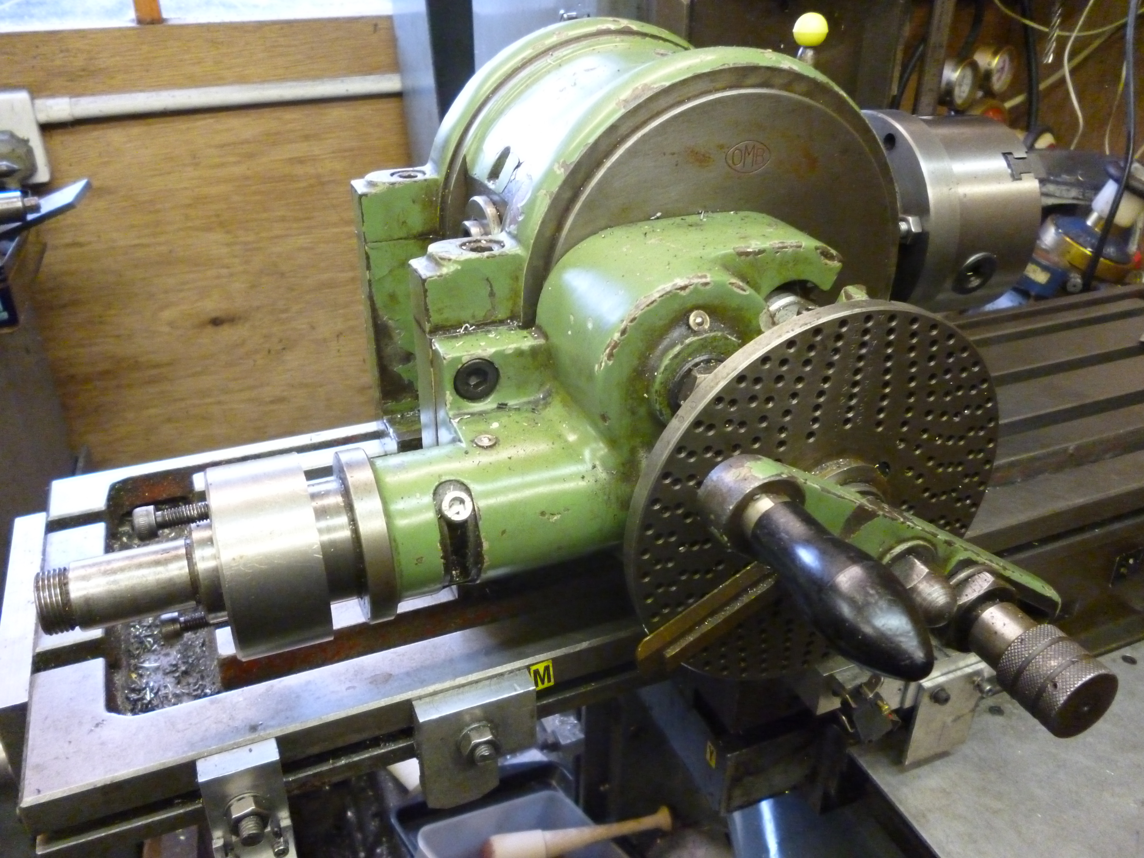
On all dividing heads the worm is turned by means of a handle. The handle either contains a retractable pin or the other end of the handle contains a pin that can be locked into a hole in a dividing plate.
Handle with separate indexing pin on a dividing head – 568
This plate has several rings of holes spaced equally around the plate. The number of holes in each ring is different. The indexing pin, whether it is in the handle or separate, can be set so the pin will fit in any hole in any one ring of holes on the division plate. Using this means that movement of the spindle on the dividing head can be made by any number of spaces.
This handle might appear to be just a handle. But when using a dividing head to make, for example, a spur gear, there are a large number of movements the operator must make using this handle. The handle shown above is just about as good as possible. The features to watch out for are:
The handle for turning and the pin for locking are separate. This means the handle is always as far out as possible.
The pin can be moved completely independently of the handle to any ring as required.
The pin can be retracted and, by twisting it, it stays in the retracted position.
The two sector arms must be completely locked together relative to each other.
The sector arms must move freely but not able to move unless pushed by the operator.
These requirements are to minimise the effort required by the operator and reduce the risk of error.
Dividing plate
The dividing plate is the key to dividing the circle. Often a dividing head is supplied with three dividing plates. Each plate contains a number of rings of holes. This means that one turn of the handle can be divided into the number of holes in the particular ring. Working this out is covered under “Dividing the circle”.
On some dividing plates the holes are only drilled to nearly halfway through the plate. There is another set of rings of holes on the other side of the plate so the plate can be fitted and used either way round.
When the dividing plate is fitted properly all of the “zero” holes will be in line and will be vertically above the shaft of the handle. Usually, next to each of the zero holes, is stamped the number of holes in the ring.

1030 dividing plate showing first holes of each ring
The ring of holes are usually arranged so as to contain as factors all of the primes up to about 47.
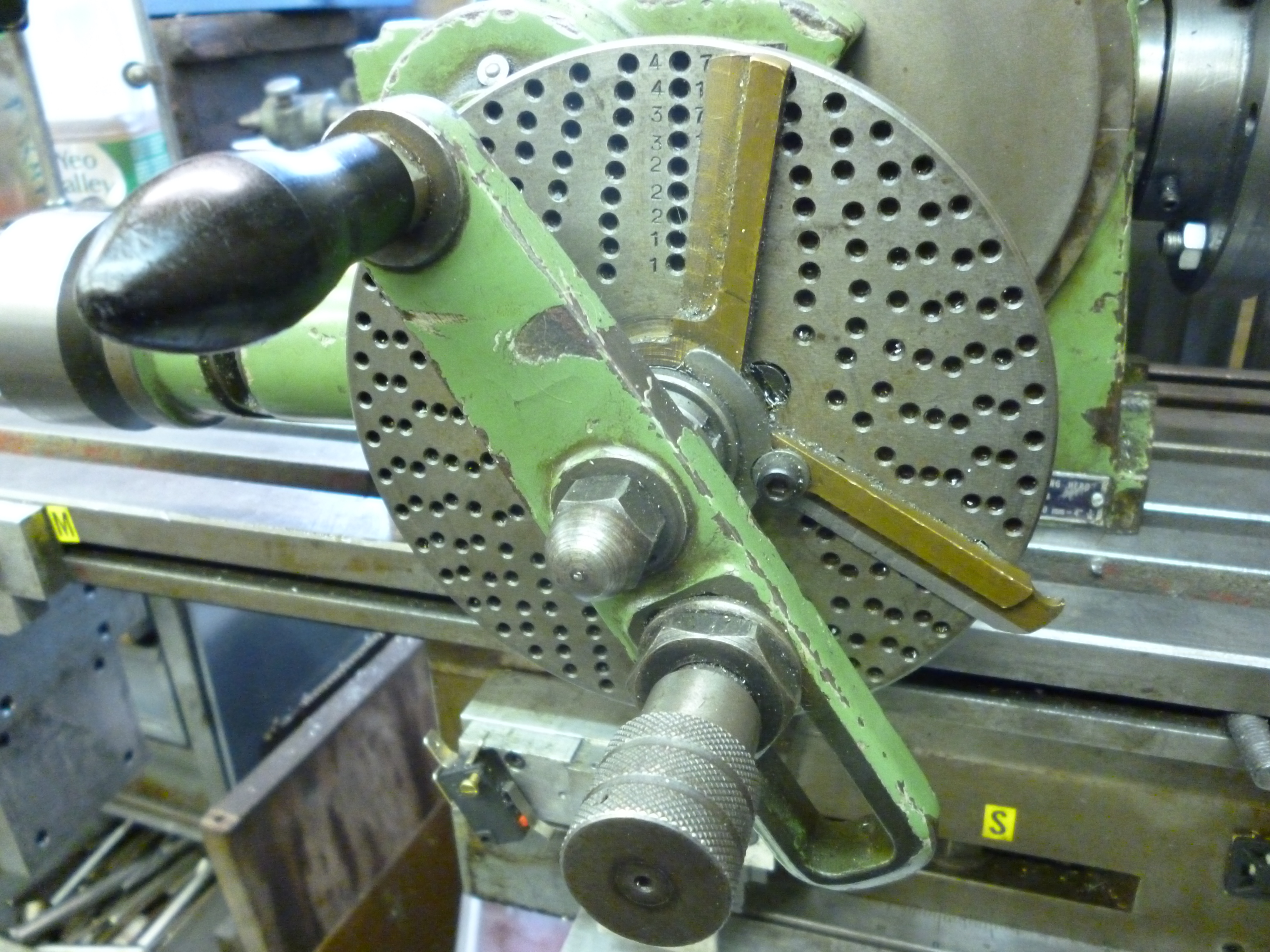
The sector arms
The two black parts in the above photo are the sector arms. These can be set so as to encompass any particular number of holes. When set like this, these arms can be locked together as a pair and can be rotated together as required.
The sector arms are a neat way of enabling the user to move the handle by a certain number of holes easily and quickly and accurately. This is an essential feature when cutting gears.
Suppose we have just cut one tooth then:
In general the pin is set to one hole. The left sector arm is touching the left of this hole. The handle is rotated clockwise so the pin is just touching the left of the right sector arm. This has moved the handle by exactly the number of holes between the sector arms. The sector arms can then be rotated clockwise till the left arm is just to the left of the new position of the pin.
Now the workpiece is in the necessary position to cut the next tooth.
Indexing ring
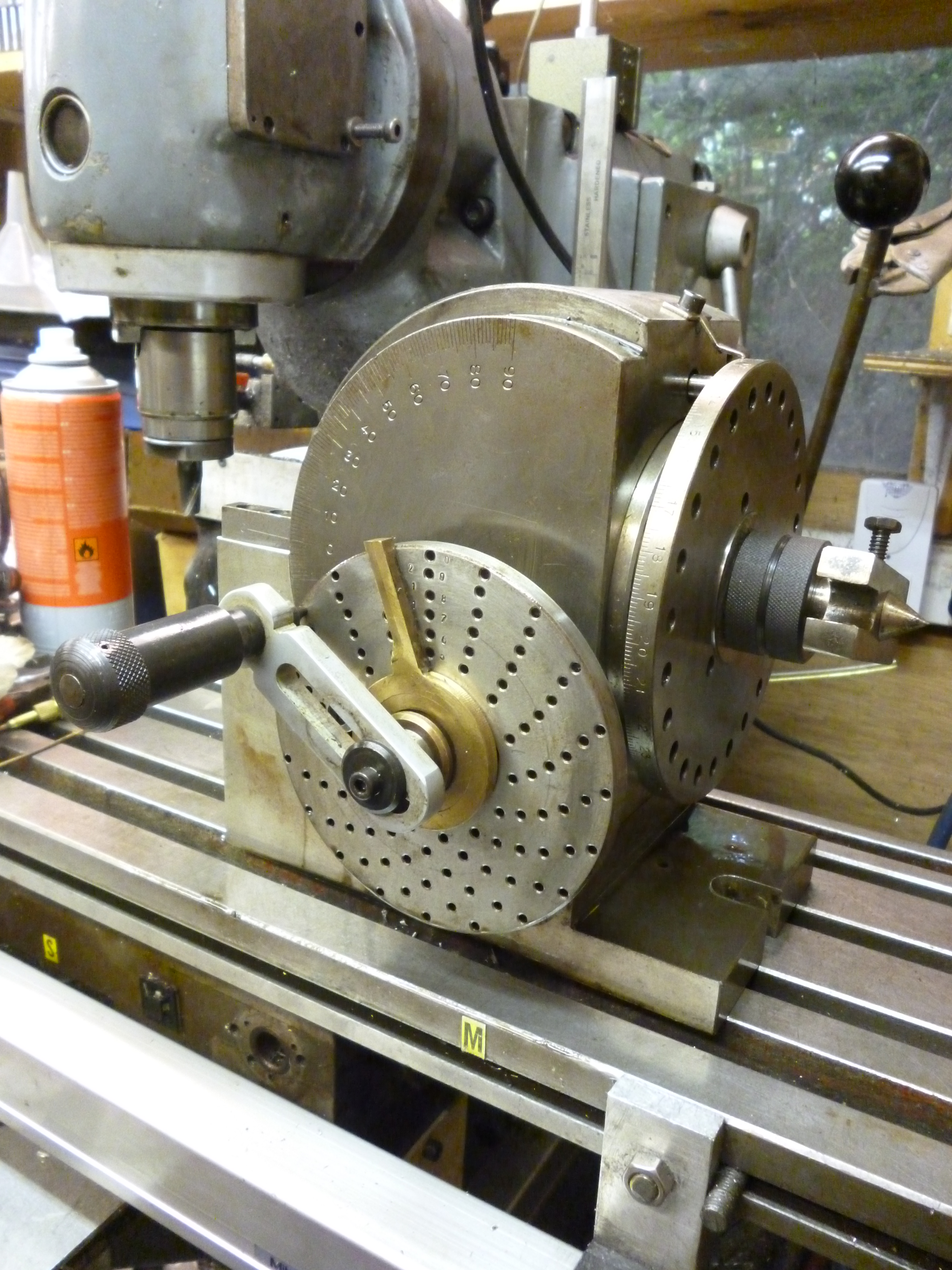
As a completely separate feature a dividing head often has an indexing feature that is separate from the division plate. This means that the shaft of the dividing head can be used as a simple index head.

628 indexing on the dividing head
In the example above, the holes for indexing are just to the left of the division plate. The indexing pin is the black knob on the top of the dividing head. On larger dividing heads, where the wormwheel is totally enclosed there may be a completely separate plate that can be fitted on the main shaft just for indexing.
Engagement of the worm and worm wheel
On all types of dividing head there is always some sort of mechanism that means that the worm can be disengaged from the wormwheel.
This has two uses. It can be used to adjust spacing to minimise the backlash between the worm and the worm wheel. But it can also be used to completely disengage the worm from the worm wheel. This would be, for example, essential when using the indexing feature.
On the plain dividing heads the shaft with the handle is fitted so the worm can be moved away from the wormwheel.
Control of engagement of worm and wormwheel – 696
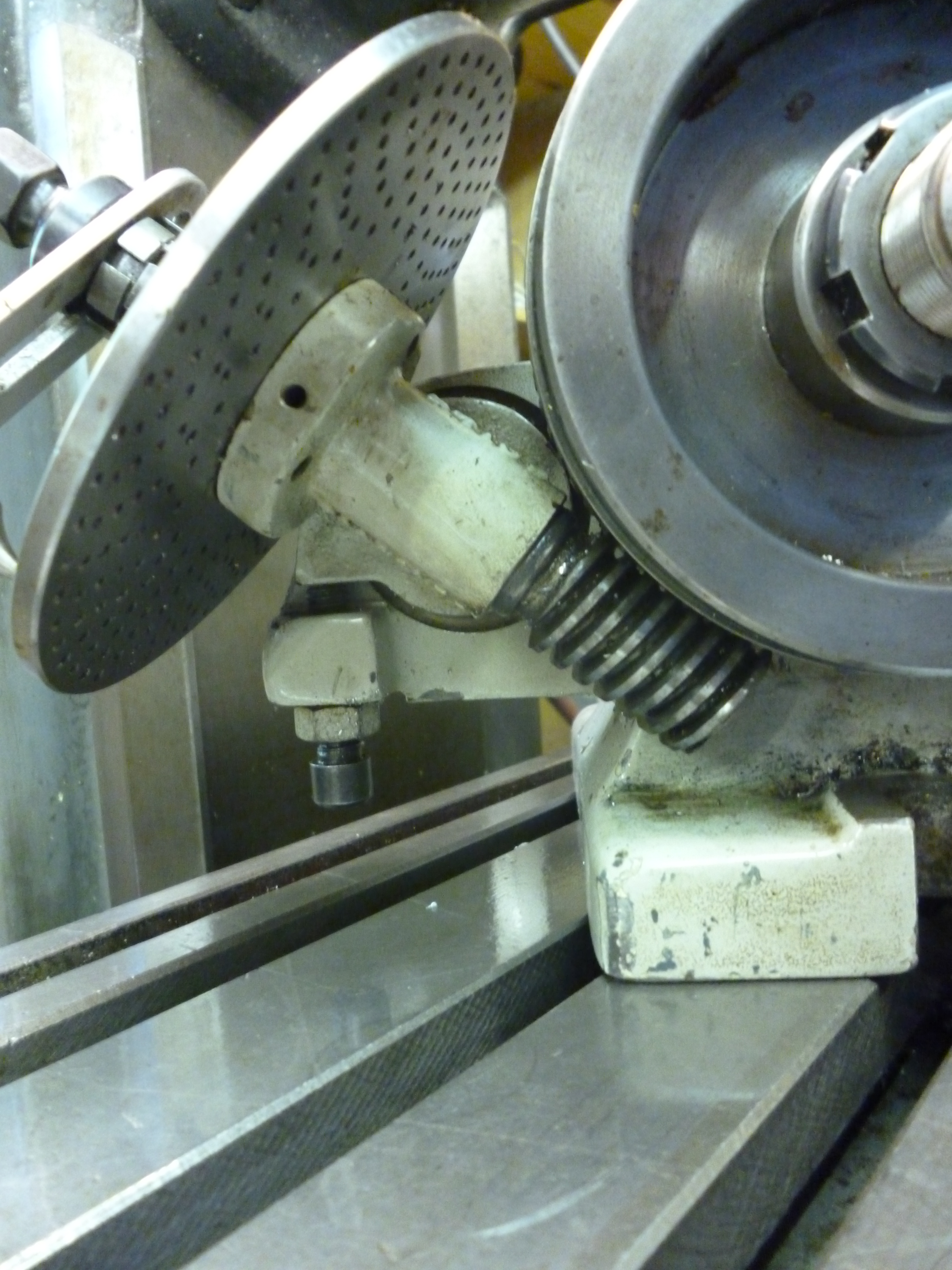
On dividing heads that can be tilted, the shaft the handle is mounted on is fitted eccentrically in a sleeve that can be rotated. This not only enables the spacing between the worm and wormwheel to be adjusted it can also be used to disengage the handle from the shaft driving the worm. The fig. shows the arm for controlling the engagement of the worm and worm wheel.

Control of engagment of worm and wormwheel on universal head – 590
If the shaft with the worm is moved so the worm is not engaged with the wormwheel then the gear that links the division plate and the series of gears that led back to the auxiliary input is also disengaged.

Gearing between auxiliary input and worm shaft – 589
In the above photo, the dividing plate and the lower gear are permanently connected together. The handle which is to the left of the dividing plate is connected to the shaft which is fitted with the worm. This is inside the dividing plate/bottom gear assembly. When the worm is disengaged this shaft moves downwards so that the bottom gear in the photo is disconnected from the gear above it. This top gear is is connected to the auxiliary input. In this situation the dividing plate etc. is free to rotate. When the worm is disengaged what happens here has no impact on what is happening to the main shaft.
When the worm is engaged The diving plate can be used in one of two ways. In the first it is locked. This is done by a small tab which is held in place by the cap screw at the top of the preceding photo. This tab fits in a slot on the back of the dividing plate.
Alternatively, when the auxiliary input is in use this tab is withdrawn. The auxiliary input drives the top gear. The worm is engaged with the wormwheel. So the top gear drives the bottom gear. This rotates the dividing plate. The pin on the handle is in one of the holes on the dividing plate. As this handle rotates so does the worm and hence the wormwheel and workpiece.
One consequence of this is that when the worm is disengaged it is not possible to drive the auxiliary input using the handle.
The spindle
The spindle always has a hole all the way through it. At the front end, the spindle, on larger dividing heads, often has a taper and/or a thread or some other means of holding a chuck.
On larger dividing heads the spindle has, at the back end, a thread so that an extension shaft can be screwed into it. This enables the dividing head spindle to be driven directly, but this will only work if the worm has been disengaged from the main shaft.Though this is a rather unusual feature it is, surprisingly, one that could be easy to implement on any homemade dividing head.
It also enables the rotation of the spindle to fed back into the auxiliary input, where fitted, to enable differential indexing.
Locking the spindle on the dividing head
Rather like the rotary table the dividing head always has some means of locking the spindle in the same way as the table can be locked on the rotary table. And it is used in a similar way. If the workpiece is being machined between two points the lock has to be off. If the workpiece is to be machined at one point, as when cutting a tooth on a spur gear, the spindle should be locked.
Control of engagment of worm and wormwheel on universal head and spindle lock- 590
The spindle lock is the lever with the yellow knob on it.
Handedness
It might seem odd but dividing heads can be either left or right handed. That is, with the dividing plate facing the user, the nose of the spindle can be either to the left of the dividing head or to its right.
This is significant is when a universal dividing head is driven by the leadscrew on the milling table. If the auxiliary input is on the left then access to the leadscrew will have to be on the left. If the table has power feed at one end then, often, the dividing head will have to have its auxiliary input at the other end of the table.
Size/Weight
A key feature of a dividing head is the center height. This is the height between the axis of rotation when the shaft is in the horizontal position and the milling table. In general, the higher the center height the better. But this of little use if the largest diameter of workpiece will not fit between the milling table and the bottom of the cutter being used.
Even more important is that it is too big if it cannot be safely and easily moved on or off the milling table. The weight goes up far faster than the center height. A center height of 100mm could easily be the most that many model engineers could safely manage.
Use of raising blocks
If the dividing head is in the horizontal position, the maximum diameter workpiece it can hold is bit less than twice its center height. This can be increase by mounting the dividing head (and the tailstock if used) on raising blocks. But whether this is useful depends on whether there is still enough space between the cutter and the milling table.
In the figure another use is shown. In this case the dividing head is raised so its axis is near the height of the spindle when it is nearly horizontal.

Use of raising “blocks” – 611
The auxiliary input
Universal dividing heads have an auxiliary input at the back of the head. This is used for helical milling. This is where, as the milling table moves along, the leadscrew is used, via a gear train, to rotate the workpiece being held by the dividing head.

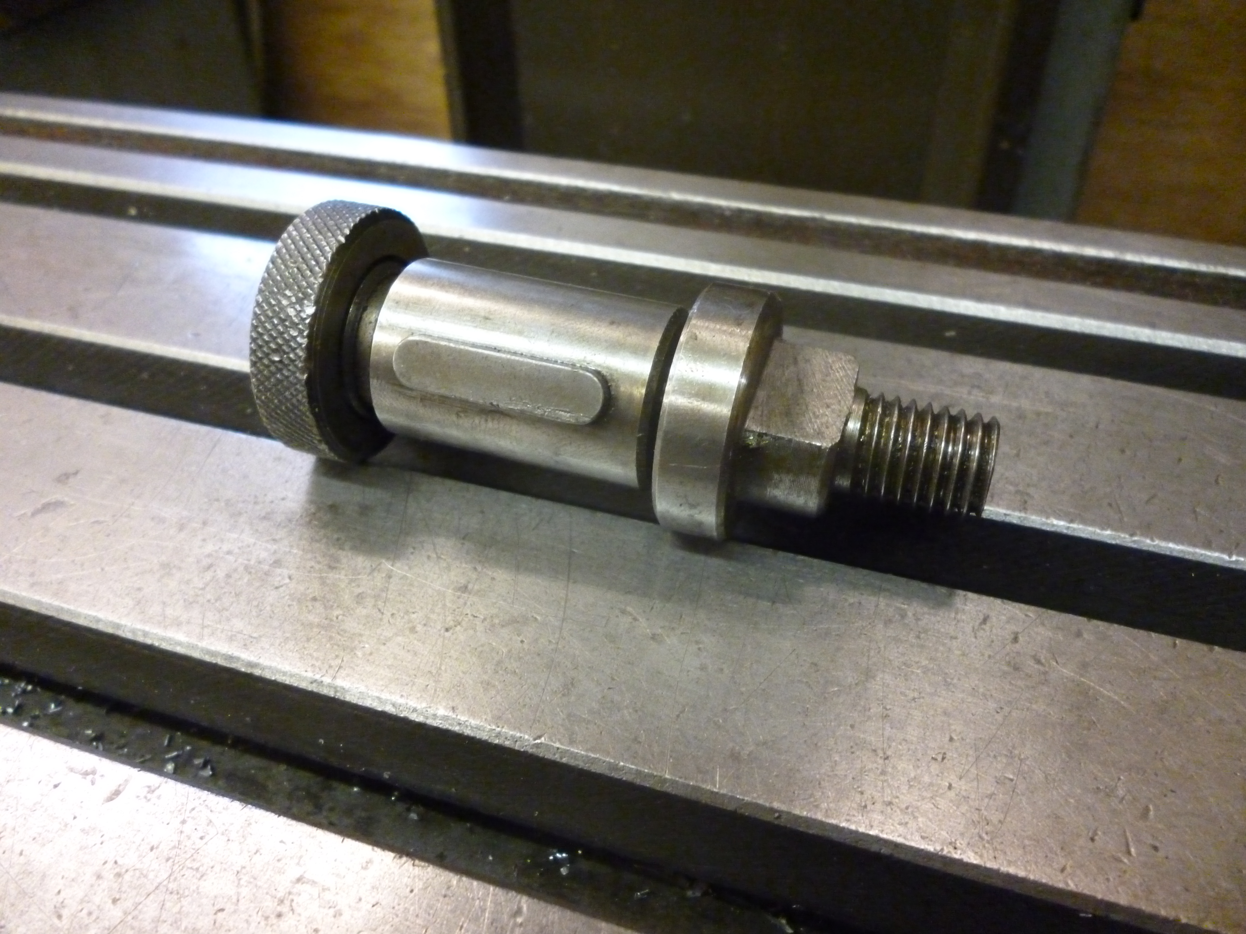
Auxiliary input shaft – 587
Notice that the exposed part of the auxiliary input is only the near end of the shaft. The large diameter bit is a boss. This is used for fitting the quadrant arm onto the dividing head.
Quadrant arm
Often when the auxiliary input is being used this will involve a gear train. The gears are mounted on an arm that fits a boss round the shaft of the auxiliary input. An arm like this is often used for a similar purpose on a lathe. On the lathe it often is designed to rotate through 90° and so is known as a quadrant arm. On a dividing head it is usually just a straight arm. It rotates simply by the angle it is fitted onto the boss on the auxiliary input of the dividing head.

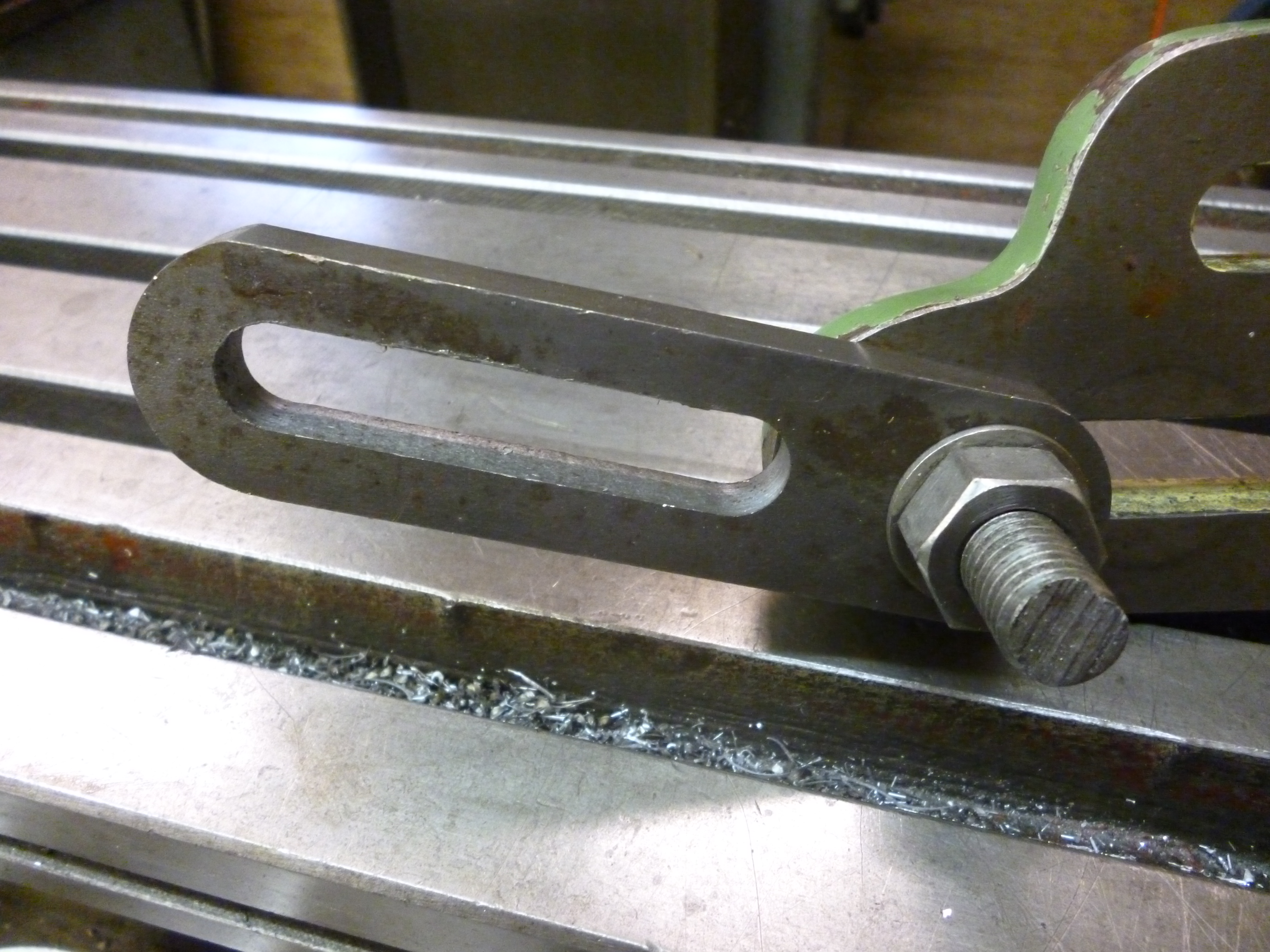
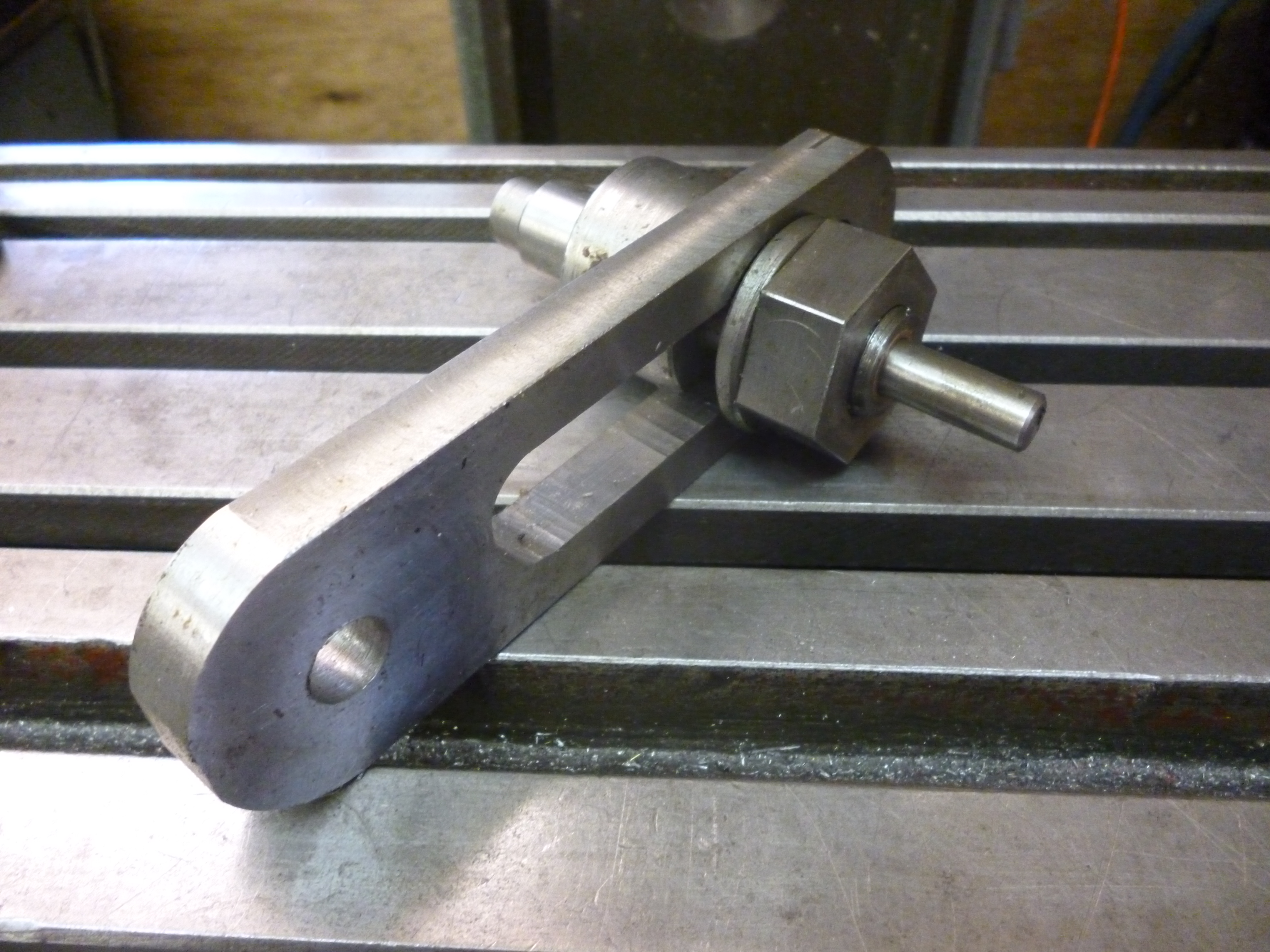
Quadrant arm – 606
Quadrant arm for fitting to a dividing head head
Stub axles
A gear train often starts with a gear on one shaft such as the end of the leadscrew. At the other end it is often on the auxiliary input to the dividing head.
Gears in between are usually fitted to stub axles that fit in the slot in the quadrant arm.
Stub axle – 608
This is covered in more detail later when helical milling is dealt with.
Extension pieces
It will be seen that the arm usually supplied does not meet all the uses the user might wish to use it for. Firstly it is not always long enough. This can be dealt with by small extension pieces.
Quadrant arm extension piece – 610
Where an extension piece is used a special stub axle is needed so that the gears on it are in the same planes as those on the ordinary stub axles on the arm.
Feed through
It is sometimes useful to have the drive coming from the front of the arm and going through to the back. This can be done with an extension piece that has a special stub axle fitted to it.
Feed through – 668
Next page – “Dividing head – holding the workpiece”

What make is the plain dividing head in picture 628 please?
This dividing head was made by Jones and Shipman of Leicester. I think I bought it on ebay for about £200.
john f
Thanks very much. I have a similar one acquired s/hand but no makers name plate on it, now I can do some more research.
Mine has “J & S” stamped on what is the edge of the chucks back plate.
john f
Gday John F
I have a Vertex semi universal but want to cut helical gears. Have you ever seen anyone drive the hand crank shaft with a gear train from mill table feed shaft? Would be doable I reckon but can’t find example on internet. Thanks for any help.
Cheers
John
sorry about the delay.
If you want to cut a helix then the usual way is to use a universal dividing head ie one that has an auxiliary input.
If you dont haqve one with this input then the method is to fit a drum on the shaft of a dividing head. There has
to be a means of fixing a template on this drum. The head of the milling machine is fited with a fixed pin that
runs against the template. So, as the milling table moves along, the pin forces the shaft of the didving head
to rotate to make a helix – according to the shape of the template.
I have done this in the past and I would think I have a picture of this somewhere on my website.
john