Back to the home page
go back to workholding
T-slots
All traditional milling machines use T-slots along the length of the milling table to hold a workpiece or some device which is used to hold the workpiece. One alternative is to us threaded holes, which can then take studs. This can be a useful alternative on homemade work holding devices because drilling a pattern of holes and tapping them can be easier than milling T-slots.
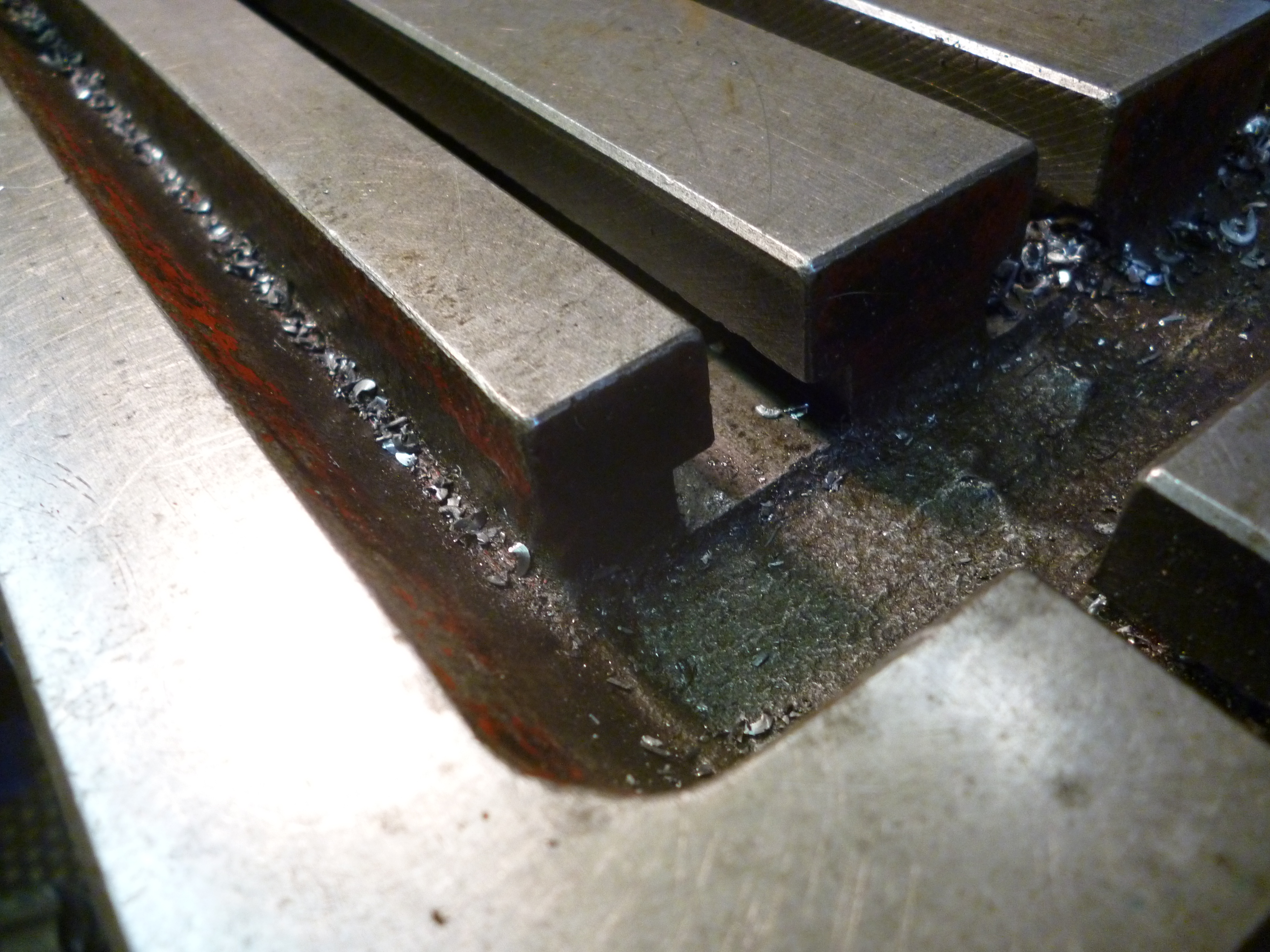
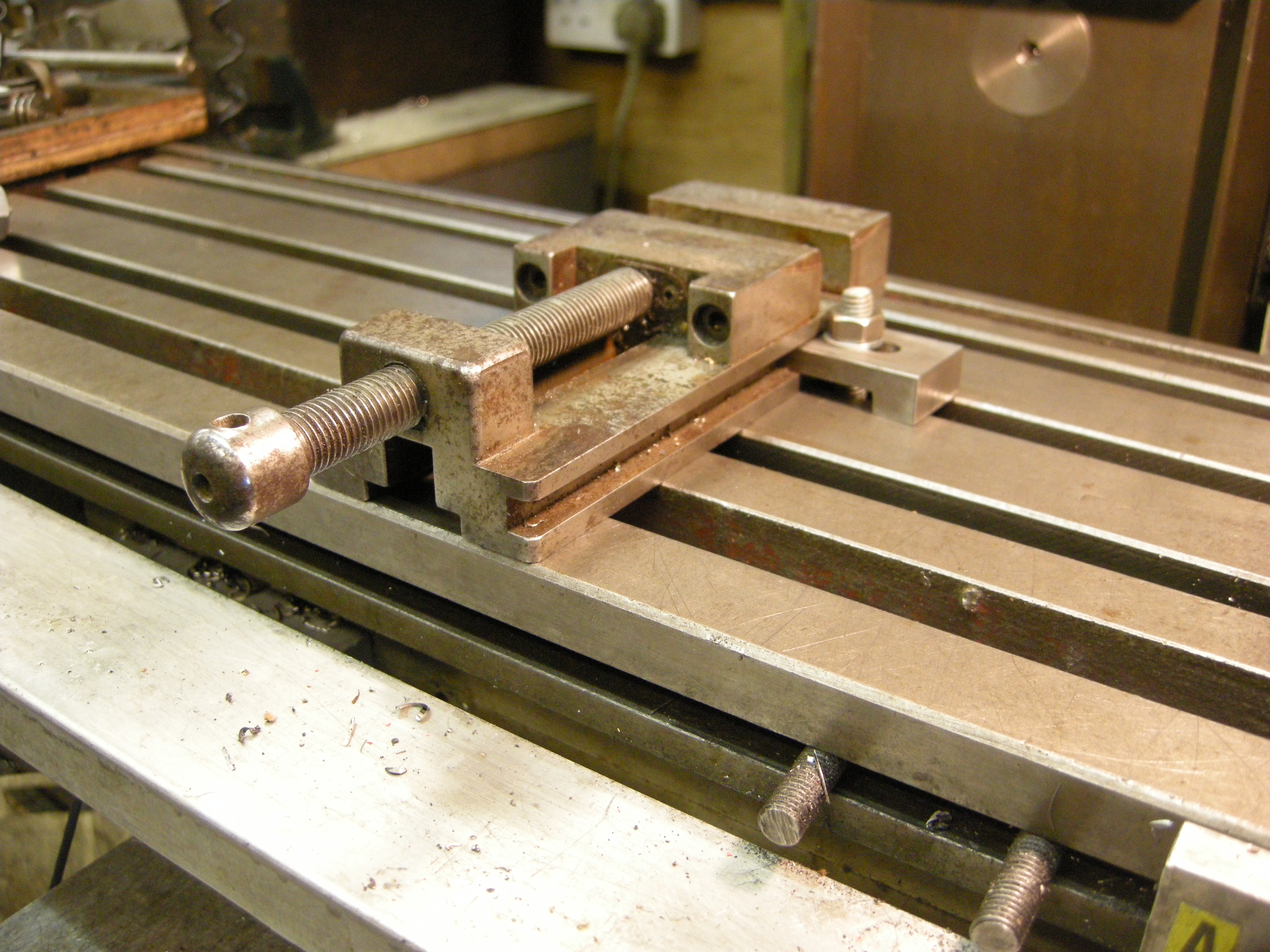
T-slots on a milling table 729
It can be seen in the above photo that the area the T-slots are in is enclosed, ie any coolant on the table is trapped and can be piped off the a collecting tank. In this case the maximum length of a T-nut is limited to the length of the space shown above. On small milling tables the T-slot extend from one edge of the table right trough to the opposite edge.
T-nuts and studding
If the milling table has T-slots then the traditional method of holding workpieces or devices that could hold workpieces is by using T-nuts. These would fit into the T-slot. They would have a threaded hole in them that could take a piece of studding or a rod with a thread on either end.

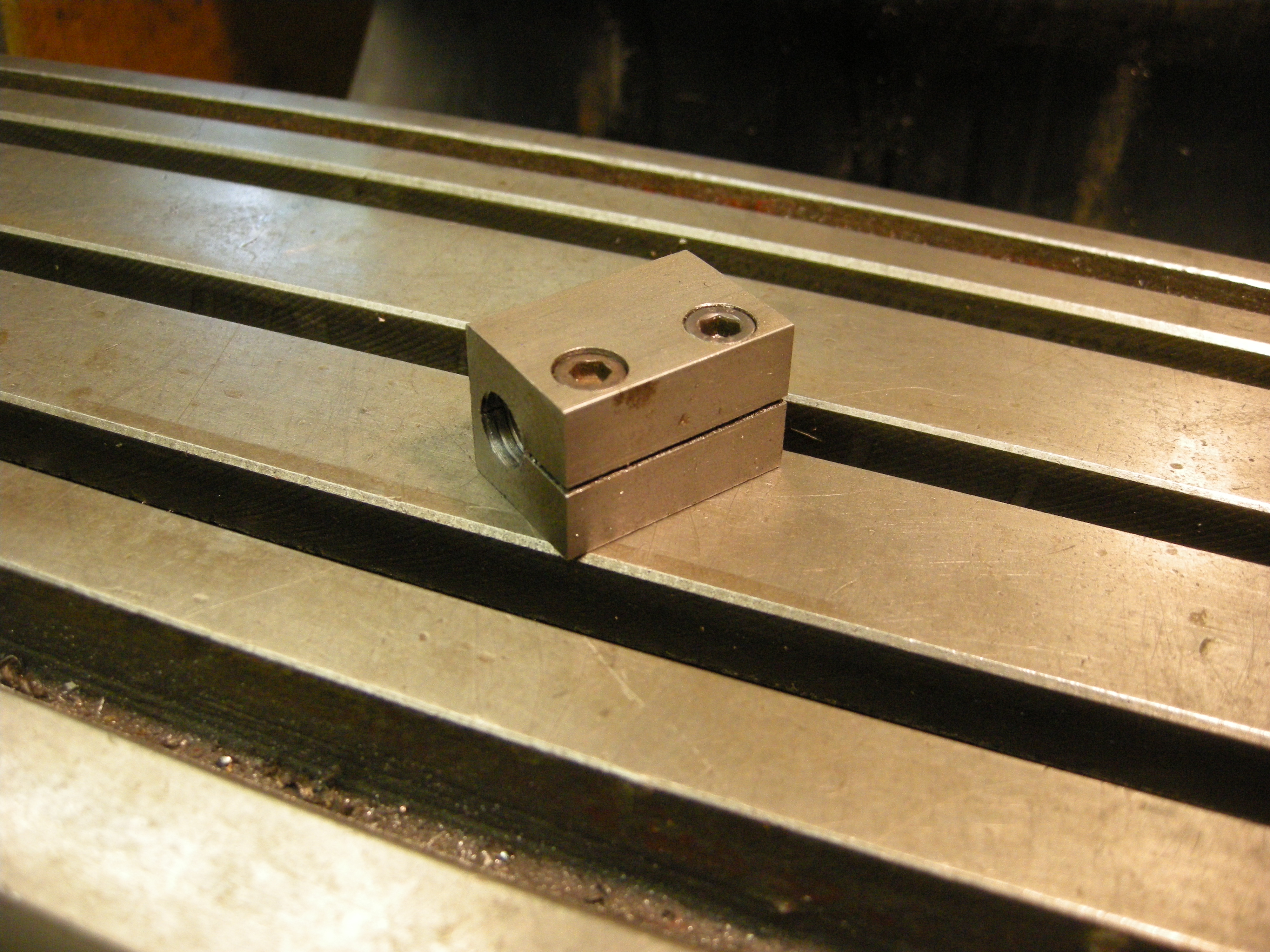
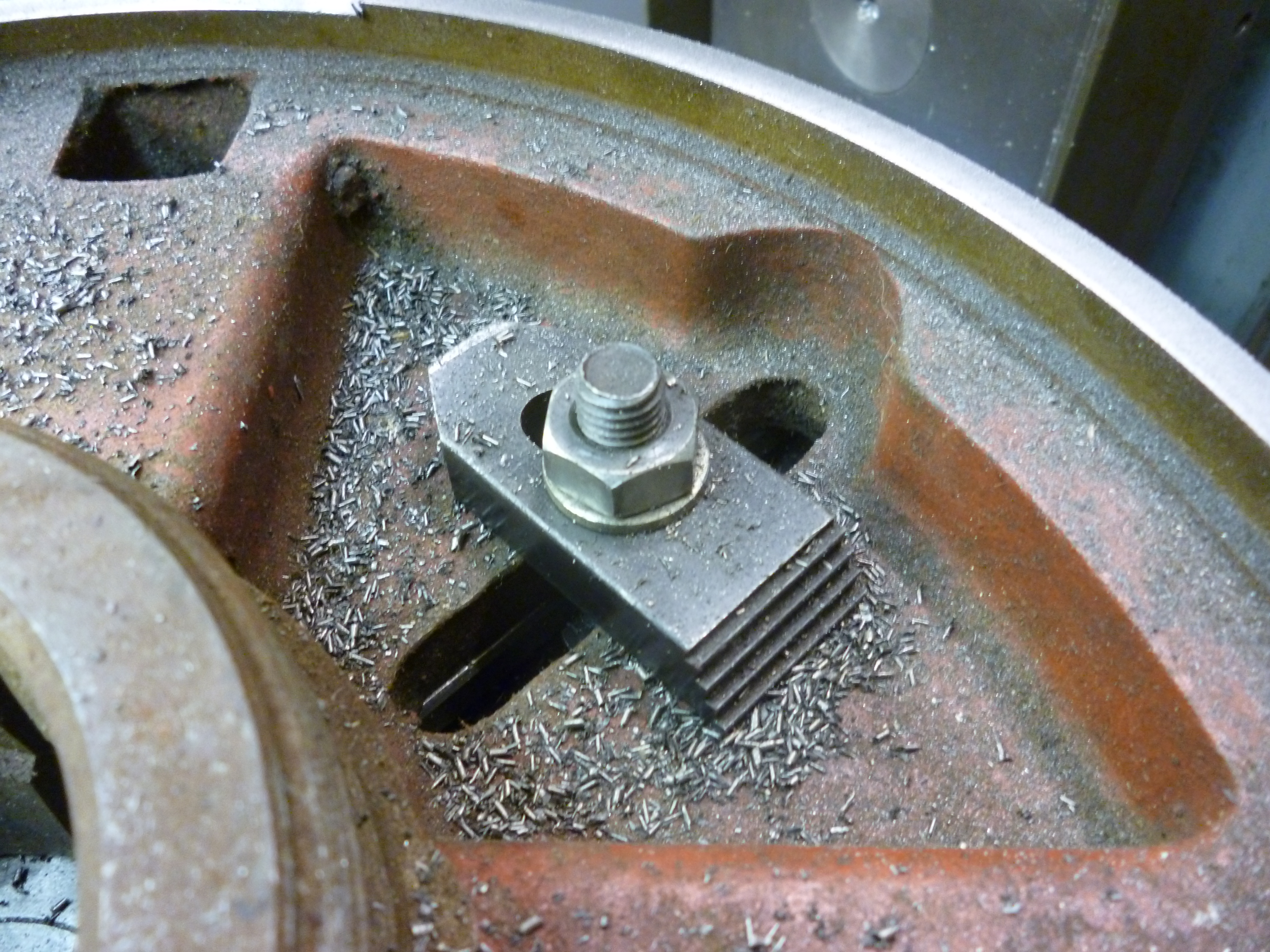
T-nut 217
This could be used to hold a clamp or bolt a vice etc to the milling table.
The nut should be big enough to make the full use of the strength of the metal available to hold it but it must be loose enough to slide along the slot easily – even if there is a small amount of swarf in the bottom of the T-slot. For a metre length table the nut should be about 30mm long. For a table about 1/2 metre long a nut about 15mm long should be strong enough.
Often, the thread on the underneath of the T-nut is spoilt deliberately so the studding cannot go all the way though.
When a complete set of bits for clamping is bought it will contain specially made studs of various lengths. But any studding will work perfectly well. Usually the studs or studding used should be the largest diameter of a standard size of material that will fit the slots on the milling table.
Wherever a T-nut and studding is used the other end will have a washer and a nut to complete it.
A T-nut can only be fitted from the end of the T-slot. However it is possible to make a T-nut in the shape of a rhombus. The point of this is that, one way; it has the cross-section that fits the T-slot. The other way it is narrow enough to be able to be fitted into the T-slot.
Fig- rhomboid T-nut
A rhomboid T-nut cannot be tightened up as much as the ordinary T-nut of the same size. It will not work in circular T-slots.
T-nuts are easy to make. Studding, either metric or imperial, can be bought very cheaply from most DIY stores. Nuts and washers are very cheap. It is a false economy not to have plenty of them readily to hand.
Some workholding devices that would usually be mounted on the milling table might have slots in them that are too small to take the biggest bolts that fit the milling table. In this case either the slots on the device can be milled to take a larger bolt or special T-nuts that fit the milling table properly but which take a smaller size of studding can be used.
For example 1-2-3 blocks might only take 10mm diameter studding but it could be useful to be able to clamp them to a milling table with 12mm slots. What is needed is T-nuts for a 12mm slot but threaded with a 10mm thread.
An advantage of using T-nuts and Studding
The main advantage of using T-nuts and studding is that very few T-nuts are needed and studding is cheap and can be made to any length required easily. But this means the user is constantly recycling the T-nuts. It will be seen further on that it is very useful to be able to have bolts of very specific lengths for holding some devices. Also on some devices, like clamps, it can save a lot of time for the clamps to be left with the last used bolt left in it. This would require many T-nuts.
Sometimes it is useful to use the holes in a workpiece to clamp it to the workholding device. At the same time it might be necessary to mill holes in the workpiece even where there might be a bolt. All of this has to be done without moving the workpiece. One advantage of using T-nuts and bolts is that the workpiece can be clamped with these at a certain place during the milling. It is then possible to remove the bolt but leaving the nut underneath. It is even possible to replace a bolt later using a T-nut underneath the workpiece.
Coach bolts – The alternative to T-nuts
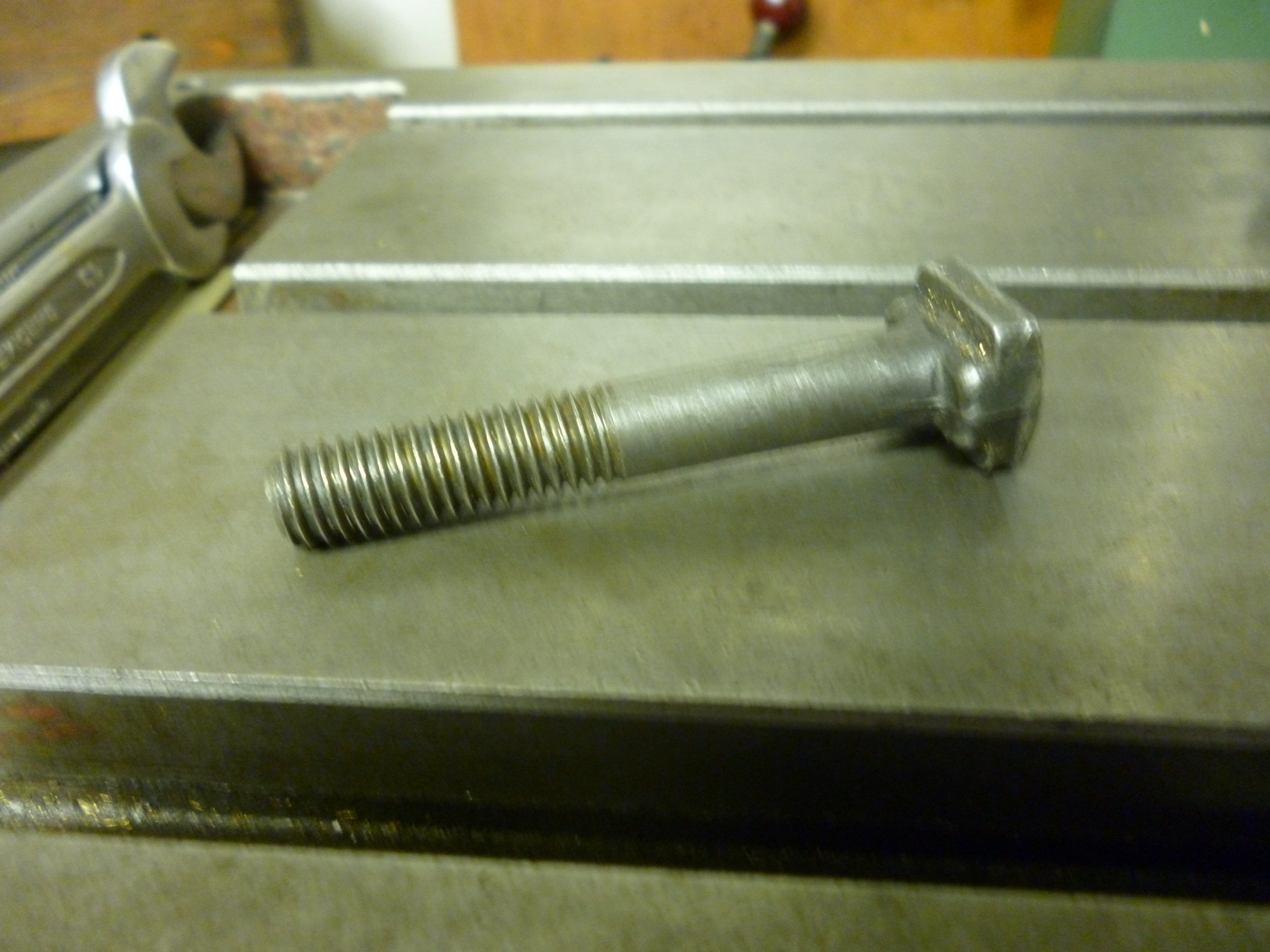
Alternatively it is possible to make a combined T-nut and studding by using a coach bolt whose head is turned and milled to fit the slot. These can also be bought in other sizes to fit any other size T-slots as necessary.

modified coachbolt 260
The head is first turned so that the depth fits the slot. The bolt is then held in a block that is threaded and can be tightened to hold the bolt.
Jig for holding a coachbolt for machining 237
This jig needs to be done up surprisingly tight if the bolt is not to creep round during milling.
Using this, the sides of the bolt can be milled to fit the width of the T-slots.
It can also be worth just skimming the sides of the square part of the shank which can be slightly bigger in places than the nominal width of the bolt.
Bolts like this are also available commercially.
Clamping bolt 624
On not using hex bolts
Usually, it is not sensible to use bolts with hex heads because the amount of metal under the edges of the slot is too small and doing this could impose too great a stress on these edges. This could damage the edge of the T-slot but it could even just break a piece of the T-slot off. This then stops anything from sliding along the slot freely. Furthermore unlike the T-nut or modified coach bolt there is nothing to stop it from rotating in the slot.
Even where a hexagonal head appears to fit the T-slot the length of the head is shorter than a T-nut would be so the stresses on the T-slot would be higher.
Forces on T-slots
With a T-nut and stud or with a combined nut and stud, i.e. modified coach bolt, there are two possible situations that can arise when using it. The first is where the stud goes through the T-slot and then though some metal, be it a workpiece or a work holding device that surrounds the stud. Then there is a washer followed by a nut.

clamping – case 1 – 522
In this case it is clear that the possible clamping force is not limited by the tensile strength of the material of the milling table but by its compressive strength, which is far greater than the tensile strength of the stud. This is the case where a vice is clamped to the milling table. This can be tightened very tightly without any fear of breaking anything. Two surfaces clamped like this can be assumed to be unmoveable.
The second situation occurs when the workpiece or workholding device does not surround the stud. This is the case when the T-nut, bolt etc are used to hold a clamp. In this case the force tends to pull the edge of the T-slot up. The sides of the T-slot are subject to a very high tensile stretching force. Considering that it is probably made of cast iron and that the bolt is made of steel means there is a risk of breaking a bit of the T-slot off.
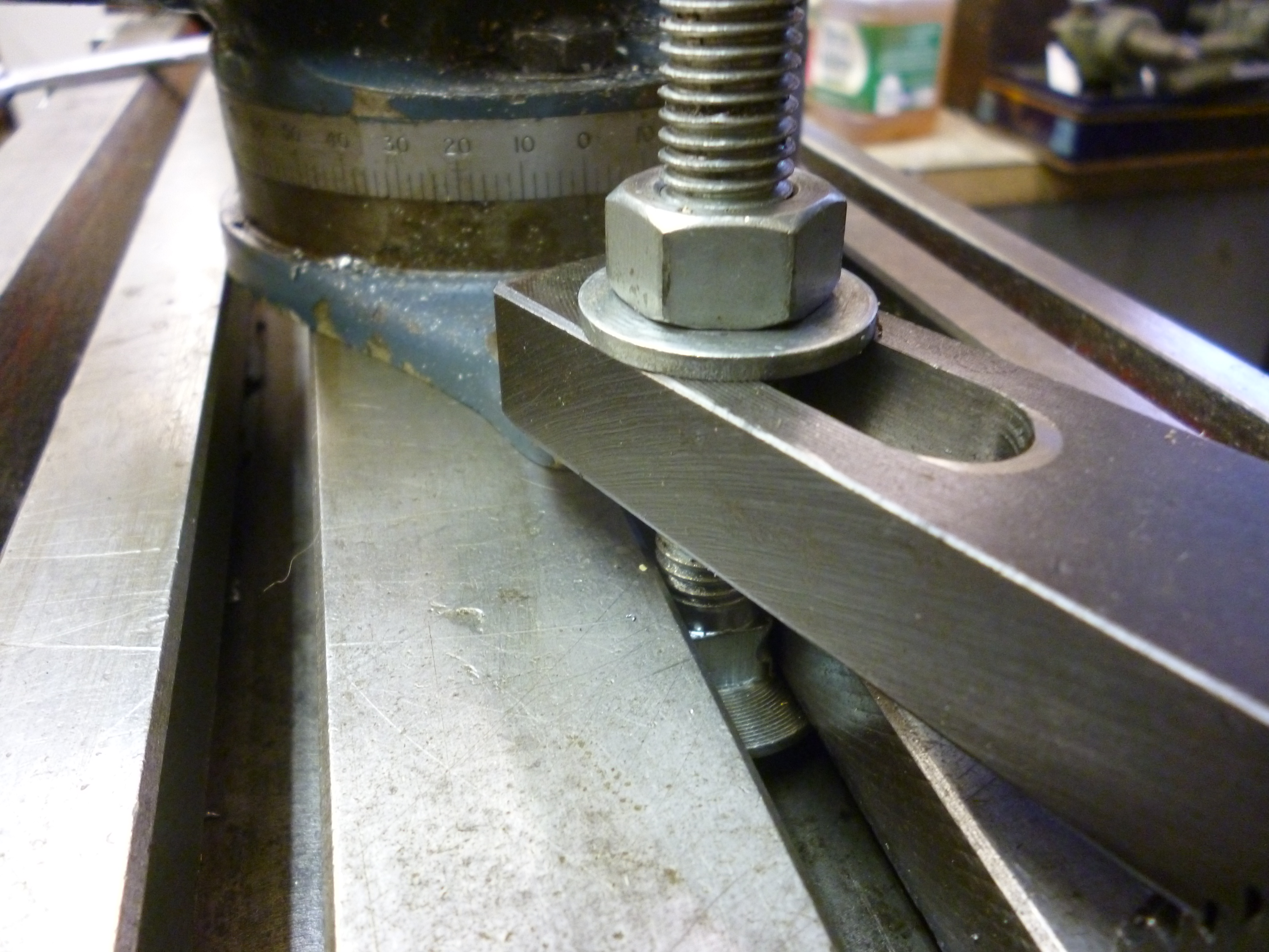
Clamping – case 2 – 523
In this case the nut can be tightened with only moderate force. In some circumstances whatever is being held this way can be forced to move. This could happen, for example, if the cutter hits a clamp.
T-slots at right angles
Some devices, for example, a rotary table, might have two sets of T-slots that intersect each other at right angles. It is easy to see that the metal on the corner of two slots like this has far less strength than that on the edge of a single T-slot. This is confirmed by the number of times one sees these corners broken off.
fig problem with intersecting t-slots
If possible try to avoid using a T-nut at this point.
Use of long bolts
As any bolts used for clamping get longer it becomes possible for a workpiece to twist in a way that does not happen when the bolts are short.

Using long bolts – 508
Long bolts will still hold the workpiece down. What is needed is some way of stopping the workpiece from rotating that does not depend upon these bolts. This could, for example, be a fence or fences against surfaces of the workpiece at the level of the surface of the milling table.
Clamping the workpiece to the milling table
Sometimes a workpiece happens to have holes in it that can be used for bolting it to the milling table.
Using an existing hole in a workpiece for clamping 48
If a hole is large a longer clamp can be used. If it is very large it is possible to clamp it from inside the hole.
As will be explained later, almost without exception, at least two clamps are required.
Surface clamps
If there are no holes in the workpiece so it can be bolted to the milling table then the alternative is clamping.
The surface clamp is a form of lever. The clamp is the lever. One end rests on the workpiece. The far end rests on a fulcrum and the force is applied downwards in between these two points. The ways a lever can work leads to a classification where the clamp as described here is representative of the third class of levers
Fig. 212 – the third class of levers – 1013
In this class of lever the force on the surface of the workpiece is always less than the force put in i.e. by tightening the bolt. As the bolt moves near the fulcrum the output force, that is, the clamping force is dramatically reduced. Therefore the bolt is always placed as close to the point where the clamp touches the workpiece. This means the clamp would, usually, clamp the workpiece near one of its edges and the bolt/stud would be as near the clamping point as possible.
Where the clamp touches the workpiece it must never slope upwards towards the clamping point. There are two reasons for this. Firstly, if it slopes upwards then if the workpiece moves the grip of the clamp is lessened and then, of course, nothing is holding it at all. Secondly, the shallower the angle the greater the area of contact. Of course the force holding the workpiece is the same whatever the area and so the resistance to sliding sideways is the same regardless of the area. The resistance to rotating is greater but, as will be seen, other methods are used to stop this. The risk of marking or distorting the workpiece is reduced.
Since the clamp must never slope upwards and since it is seldom going to be perfectly horizontal it means it has to slope slightly downwards towards the workpiece.
The number of clamps necessary
In general, if nothing else is being used to hold the workpiece, then, to prevent any possible rotation of the workpiece, two clamps, or the equivalent, are the minimum necessary to hold the workpiece when milling. Clearly if both were clamped near the same point the risk of rotation is high – generally, the further apart the two clamping points, the lower the risk of rotation.
Types of clamp
A clamp can either be flat or bent. If it is flat, for the reason given above, the height of the fulcrum will be slightly higher than the point of contact with the workpiece. Alternatively if the clamp is bent in a suitable way the fulcrum can be the milling table.

Flat clamp – 525
If the end of a flat clamp is shaped as shown then the angle at which the clamp can act upon the workpiece and still make a good contact is dramatically increased.

Modified clamp 333
Bent clamps
Fig. 215 – bent clamp
If the clamps are swan’s neck type then a single clamp will fit a fair difference in thickness of the workpiece. With clamps of this sort one end exerts pressure directly on the milling table. It is essential that it has some means of distributing the pressure over a small area to avoid damaging the table.
768 one part clamp 2
Fig. 216 – clamp with means of pressure distribution
The most flexible cost effective type of clamp is the flat sort, which is design to be used with a stepped block.
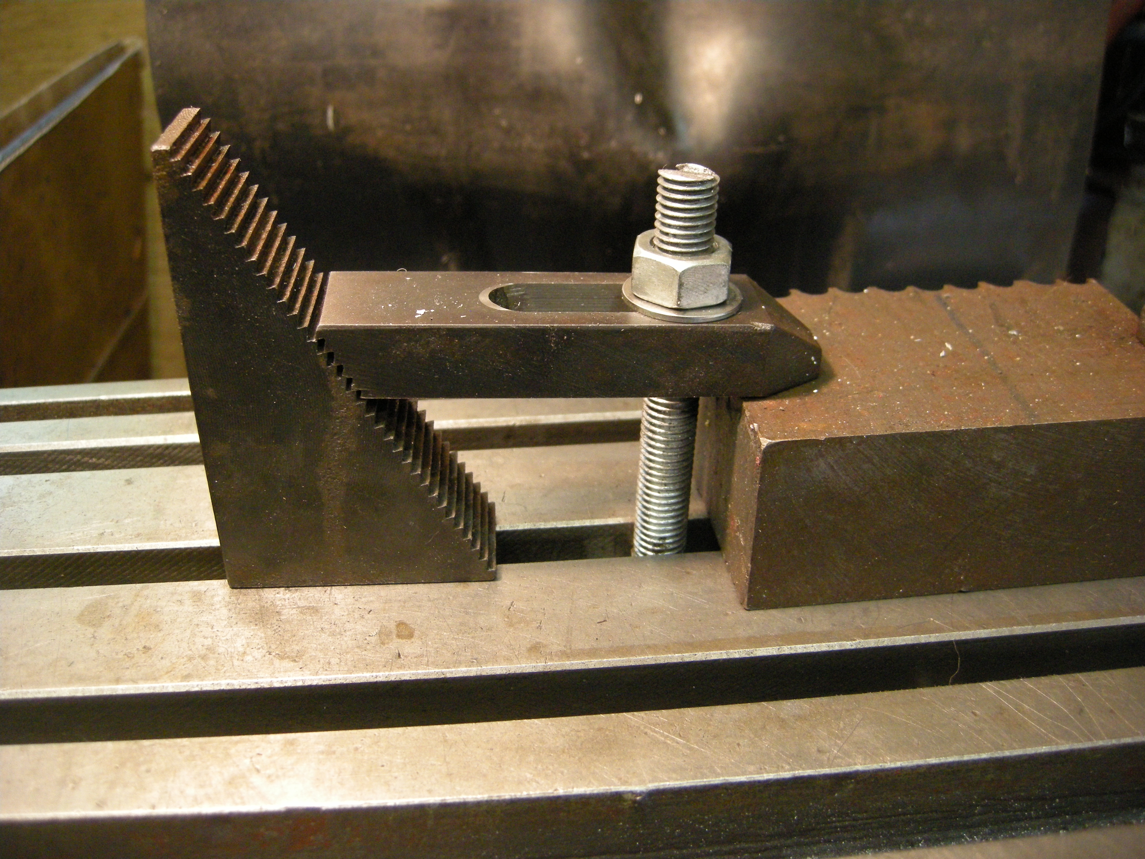
215 clamping with stepped block
The stepped blocks can only be used with a clamp that has a similarly stepped end to it.
If these clamps are bought they are usually hardened. If it is necessary to machine them, for example, to make the slot wider, they can be machined by using carbide inserts.
An alternative to using stepped blocks to adjust the height of the clamp is to fit the clamp with a screwed bolt that sets the height. The bolt can be screwed in or out of the clamp as required.

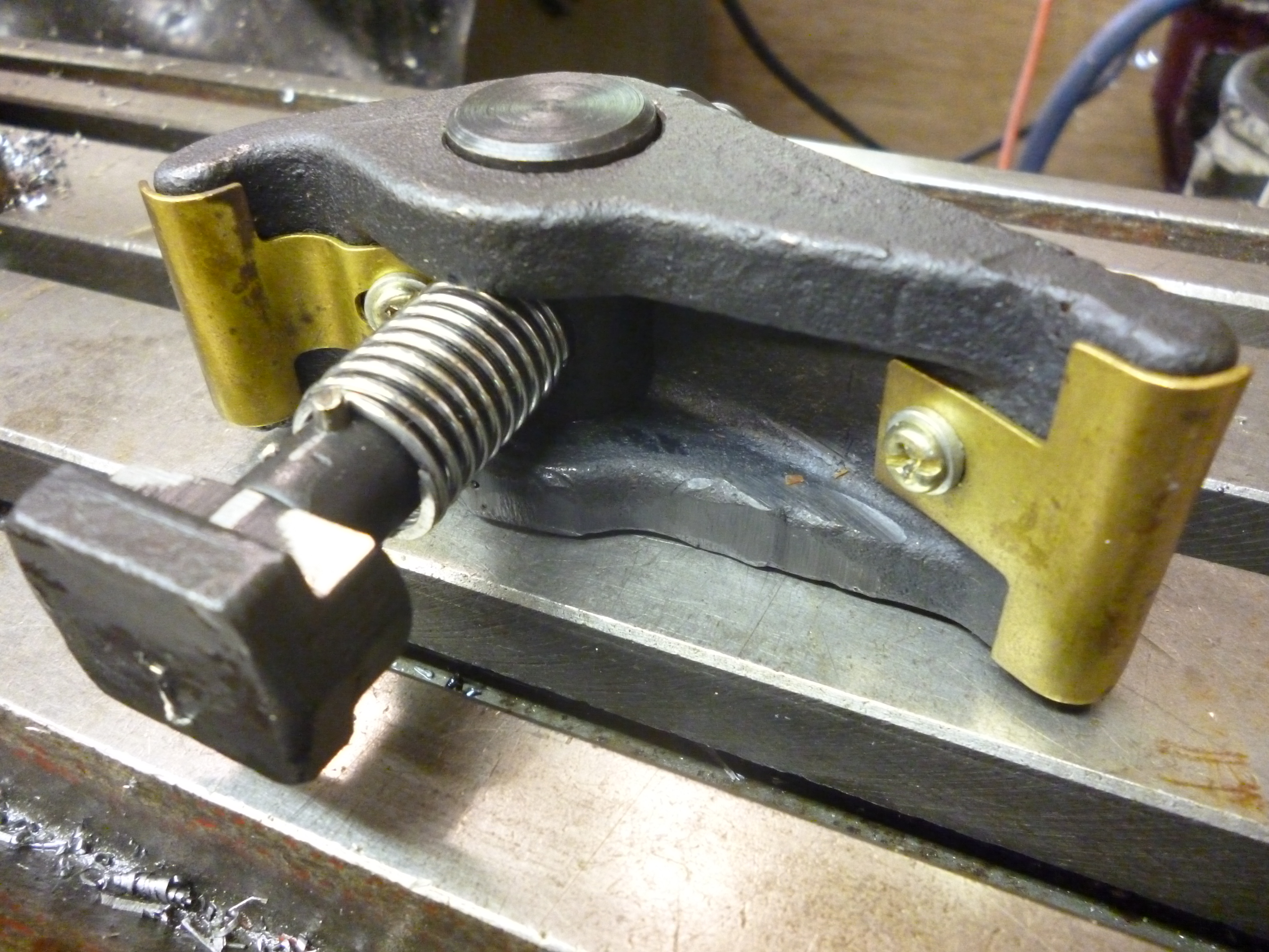
Alternative clamp 2 – 560
Notice the clamp can only be adjusted with the knob. It can only be tightened adequately with a spanner tightening the nut.
One advantage of this method is that the pivot is just one piece with the clamp and is easier to set up. If the clamp has a pivot like this and is also kept, as far as practical, with its own bolt, washer and nut, then the clamp is just one component always ready to be used without looking for anything else.
Notice that with the built in bolt it is essential that the force applied for clamping is applied to the nut and not the pivot. This is because if the pivot turns it might mark the table. One way of preventing this is to make the bottom of the fulcrum out of brass or bronze.
Size of the clamp
In general the size of the clamp used should be determined as follows. The bolt should be the largest that fits the T-slot. The clamp should then be the one with the narrowest slot that fits the bolt. Having chosen this the second parameter is the length. Short clamps give less leverage but very often the space for longer clamps is limited. Perhaps the compromise is to use the longest possible subject to the length not becoming inconvenient.
Within the home workshop, often the largest diameter T-bolts needed will be those fitting the T-slots on the milling machine’s table. These might well fit the workholding devices that are clamped to the milling table. But if these devices also have T-slots in them they will be proportionately smaller. This means it is not likely to be sufficient to have just one size of T-nut and studding, clamps etc.
It saves time to sort clamps according to the size of the largest bolt that fits the clamps and to keep these clamps, bolts etc in separate boxes.
Putting the clamp together
Wherever a bolt goes through a clamp and is then held by a nut, there must be a washer under the nut. This should not be any old washer but a washer that just fits onto the thread but is big enough to at least cover the bottom of the nut but, preferably the width of the clamp. If the slot in the clamp is significantly bigger than the diameter of the bolt then the nut that fits this bolt will not cover the clamp properly. In this case a larger and thicker washer should be made and used.
A similar situation occurs where a device, such as a vice, is clamped to something, like the milling table, where the bolt is much smaller that the slot for holding the device. In this case the washer can slide to one side of the slot. The solution to this is to make a washer that can only sit in the middle of the slot as shown.

Special washer – 315
It will be noticed that putting a chamfer on the topside of a thick washer greatly improves the appearance of the job.
It will often be found that a certain size of bolt will often be used on any particular size of clamp. It is worth having enough T-bolts so the bolt can be kept attached to the clamp even when you have finished using this clamp.
Mixed sizes
If the largest bolts that fit the milling table are, say, 12mm, it will sometimes be found that a workholding device might only take 10mm bolts. But the 10mm T-nuts will not fit. The solution is to make T-nuts that fit the T-slot that takes 12mm bolts but threaded for 10mm studding.
clamps for special purposes
Not only are clamps necessary to clamp the workpiece to the table but there are also times when it is necessary to clamp a workpiece to a rotary table or to a table on a toolmaker’s microscope. There are times when a device like a toolmaker’s vice needs to be clamped onto something.
Special clamp for toolmaker’s vice – 207
Vertical clamps
It is often useful to be able to hold a workpiece so that its wider side is vertical. One way is to hold it in a vice. This is covered later.
It is also possible to use angles plates. These are also covered later.
Vertical clamps can be improvised using toolmakers clamps.

Vertical clamping – 669
The figure shows some commercially available clamps. A key feature is the lack of height.

Vertical clamps 2 – 626
Many of the more unusual workholding devices can be useful but not very often. It is therefore always worth reusing any bits that might already be around. Most readers will already have many clamps for horizontal clamping. It is a simple matter to make a part that makes it possible to use “horizontal” clamps in a vertical manner.

Vertical clamp 3 – 670
Clamping – practical points
Finding bolts, nut and washers and fitting them to the clamp or stop takes time. It will be found that most times a clamp is used the length of bolt necessary usually within a very limited range of lengths. A lot of time can be saved if clamps are fairly permanently set up with their own bolts etc.
The same applies to many of the gadgets, which are covered later; the clamping bolts are, in most cases, of a fairly fixed size.
Sometimes a device, for example, a rotary table, may needs bolts of a special length. It is worth having a small box of special parts including these bolts kept apart especially for use with this rotary table.
Coach bolts can be bought very cheaply in metric sizes of varying lengths from Screwfix. Buy the longest size – they cost very little more. Saw them to the lengths required. But make them multiples of a unit length, say, multiples of 15mm. This makes it easier to identify which size they are.
Machining where the clamps are
Usually if two clamps hold the workpiece it is possible to machine it like this. If one of the clamps is now in the way of further machining then one clamp can be undone and moved and then used to clamp the workpiece at some other point. In doing this it is essential that the first clamp is done up really tight. This may seem obvious but it is surprising how often it is loose enough for the workpiece to move even if only slightly when doing this. The movement is not lateral in any direction but is rotational.
If it is necessary to move a clamp the solution is to clamp the workpiece with more than two clamps. With three or more clamps the workpiece will not move at all even when one clamp is moved.
Milling a part that will be milled into two or more pieces
Even if we start a milling jobs with one workpiece held by two clamps it is quite possible that by the end of the job we will have two or more pieces. Where should the clamps be? This happens when the milling machine is used to cut up a sheet of metal or where a round shape is being cut out of a sheet.
The safest method is to clamp both of the possible parts with two clamps each. When they are parted they will stay exactly where they were.
If one part is relatively small it can be allowed to fall off.
Probably the worst situation is to clamp one part with two clamps and with one clamp on the other part. In this case where the part clamped with one clamp becomes separated it cannot move away but can rotate and is likely to get spoilt by the cutter.
Use of tabs
Where a workpiece is going to be cut in two significant parts and it is not possible to clamp both of these parts properly one solution is to use tabs.
This involves doing most of the cutting but leaving the two parts connected by small tabs. These tabs are just sufficient to hold the two parts together securely. For example there could be two tabs each about 1mm thick and 10mm wide.
When the milling has been completed, the workpiece is removed, the tabs are sawn through and the remains of the tabs are filed off.
Preferred direction of holding/milling workpieces
In general, a workpiece that is longer one way than the other would be held with the long direction along the milling table. This saves time by not trying to fit it the other way and then finding there is not quite enough room for it.
The use of the x direction often has other advantages over the y direction. Often it is powered and it might have stops.
The x movement is always larger than the y movement but it is always substantially less than the length of the table. It is useful to fit two markers on the table showing the limits of where the center of the spindle can reach. This saves fitting a workpiece and then finding the cutting tool cannot reach it.
Milling the full depth of the workpiece
Often it is necessary to milling a hole or an edge right through the thickness of a workpiece, which is clamped to the table. Clearly we do not want to mark the table. The easiest way round this is to raise the workpiece up by placing it on something.
This is useful for milling the edges of sheet material especially when it is long and narrow.
The workpiece can be lifted in two distinct ways:
Parallels
Parallels are pieces of metal usually made of hardened steel. They are square or rectangular in section. The sides are square to each other and the opposite sides are parallel. Often they are about 150mm long but they can be longer and also shorter. They are very accurately made in pairs so a pair can be assumed to be identical in width and depth but not necessarily in length.
Larger ones might have an I-shaped cross section or holes in them.
Sometimes the ends are ground square but sometimes they are not.
They can be bought in sets consisting of pairs of parallels of different heights. They can also be homemade. They are still useful even if they are not hardened. But if they are not hardened they are prone to getting dings along the edges, which, unless removed, compromises their accuracy.
Pieces of HSS are often very accurate in size and can also be used as parallels.
Since parallels are usually hardened if a cutting tool should happen to run into one, the cutting edges that touch it will be spoilt.
Using wood underneath
Wood is very good for putting underneath a workpiece that is to be milled. It can be strong enough to support the workpiece. It is cheap and hence dispensable so it does not matter if it gets machined. It is easy to cut to the required shape. The thickness of the wood can be very accurate. Most plywood and MDF is quite good enough and is cheap.
If using wood underneath a piece of thin metal sheet, which is to be milled it, is necessary to use something on top of the metal sheet to spread the pressure of the clamps. Otherwise if the clamps are applied directly they can distort the sheet.
Do not leave pieces of wood or wood type materials, such as MDF, on the milling machine’s table if using cutting fluid – it is likely to stain the table. If MDF gets wet and stays wet for any length of time it swells up.
Workpiece supported on parallels and clamped to the table
Where the workpiece is a piece of sheet material that is roughly square shaped it becomes difficult to clamp along the edge of the sheet, which is being machined. In this case the edge can be supported by a parallel below and by another parallel or a piece of angle iron along the top and then clamped at either end. It is imperative that where it is clamped the clamp acts on the parallel or angle iron, then the workpiece and then the parallel.
It is also possible to use a thin piece of wood between the angle iron and the workpiece. This acts as a springy substance that will apply a pressure all the way along the edge. This is useful with thin sheet that is liable to vibrate when cut.
If cutting thin sheet with a slitting saw it is and it is only supported underneath then it is better with a slitting saw cutting downwards.
Toggle clamps
A toggle clamp is designed to clamp a workpiece very quickly and easily by hand without the need for any other tool.
This can be very useful where a large number of pieces are to be machined as efficiently as possible using a jig to hold them. In this case it is desirable to be able to get the workpiece in and out of the jig as quickly as possible and yet for it to be held securely. The strategy is that the jig holds the workpiece so it can only move in one direction, for example, in or out from the top, and it can only do this if the toggle clamp is not applied.
If a workpiece was held in place with two of these only the milling table it would not be safe. If it was held in a jig so the only way it could move would be upwards then one of these holding it down would probably be adequate.

Toggle clamp – 490
There are also toggle clamps that can be used to apply a force sideways.

Wonderful article – I am trying to find a source for side clamps like your hydrojaws or the smaller pivoted units – would you have another details ? mat.
I buy most of my stuff on ebay. Before I got these I made some out of mild steel. They worked but I dont think they were really tough enough. Side clamps seem to need to be done up more tightly than one might expect to hold the workpiece securely.
I’ll try and put some more details on the site so people can make their own.
john
If the flux is rubbed off it is very likely that the gap left will be so small any flux around will find the gap irresistable and fill it.
john