go to the home page
go to the page above this one – Milling – workholding – vices – links
Workholding – vices etc
Use of vices to hold workpieces
Apart from using clamps the most common way of holding a workpiece is by using a vice. In most cases the vice is bolted to the milling table. This is probably the most common set-up for either vertical or horizontal milling. It is usually faster to set-up a workpiece for machining using a vice than using clamps.
Vices used for milling are different from those used for drilling. When drilling all that is required is that the workpiece does not rotate. This is not difficult to achieve with a lightly constructed vice. But, when milling, very large forces can be imposed on the workpiece in almost any direction. This means that a vice used for milling is much more robust. The most obvious difference is that the force used to hold the workpiece can be much higher. If the length of the moving jaw is short but the force is high there is a tendency for the jaw to lift. To prevent this, a vice that is to be used for milling has a long moving jaw.

29 plain milling vice
Notes applicable to all vices
Fitting the vice to the milling table
Before fitting the vice to the milling table the table and the bottom of the vice must be clean and free of dings.
From the T-nut or the head of the bolt, through the material of the milling table, through the base of the vice right up to the bolt holding the vice is solid metal. Consequently the nut on the top of the bolt can be tightened very tightly since all of the metal is under compression except for the bolt itself. In general we can assume that, if these bolts are properly tightened, the vice will not move on the milling table.
A vice can be bolted to the table using slots or holes in the vice. If the vice has holes the bolt/nut arrangement has to be setup from scratch every time the vice is used. If the vice has slots it is possible to have bolt/washer/nut combination already set up that can be just slid in as required and then slid out when the vice is finished with. This saves time.
If the vice has holes instead of slots it is worth milling them into slots.
The traditional milling vice usually has slots in its base to bolt it to the milling table. There are two pairs of these slots, one on either side, and one on either end. This means the vice can easily be mounted with its jaws parallel to the milling table or at right angles to it.
Notes applicable to all vices
Holding the workpiece in the vice
When it comes to holding a workpiece in a vice the same principles apply to holding it using clamps. The workpiece must be stopped from moving along one or more of three axes. The workpiece must also be prevented from rotating about any one or more of the three axes.
Consider a small block held between the two faces of a vice whose faces are in the x/z plane. There are two types of force resisting movement of the workpiece.
There are those forces we can assume to be completely fixed – they do not rely on the friction between the workpiece and the faces of the vice. It cannot move against either face. It cannot move downwards. It cannot rotate about the x or the z-axis.
Then there are movements that are only restricted by the friction between the workpiece and the faces of the vice. These are movement upwards in the z direction, movement in the x direction and rotation about the y-axis. However tight, within practical limits, the vice is done up these frictional forces can be overcome. Usually even if the workpiece moves only by the smallest amount the tendency is for it to become even more exposed to the force of the cutter and something will have to give. The workpiece might eventually be moved right out of the way of the cutter. If this happens it will probably be severely gashed by the cutter. Alternatively the cutter might break. These outcomes are the better ones. It would also be possible for gears in the drive to the cutter to get broken.
Though we cannot eliminate this risk completely with a little thought the risk can be reduced to acceptable levels.
When horizontally milling, if the vice is lined up so the forces applied to the workpiece are right angles to the faces of the vice, then the workpiece will not slip. This might seem to be a good thing but if we consider the worst case what is going to give? Will it be the teeth on a gear in the gearbox?
The real problem is with vertical milling. Here the cutter imposes different forces on the workpiece at different times and in different directions as it rotates. The main risk is the workpiece rotating about the y-axis (if the jaws are along the x-axis).
This risk increases as the length of the workpiece in the vice in the x direction gets less and less and as the height of the workpiece increases. I.e. a square will easily rotate about the y-axis. Similarly when the overall height of a workpiece is greater than the length of the workpiece being held in the jaws. These are very rough guides. The tougher the material being cut the higher the forces and the greater the risk. The rate at which metal is removed will increase the forces and will increase the risk. A blunt cutter will greatly increase the force required to cut the metal.
In the end, most things can be machined safely if the rate at which metal is removed is slow enough.
If we need to machine the end of a workpiece sticking out of the side of the vice then the workpiece should be long enough to at least reach to the center of the vice. But if we are machining across an end of a workpiece sticking out of the side of the vice it does happen that all the forces ever applied to the workpiece are against either of the faces of the vice which will not move.
To sum up, generally when using a vice we want to machine along the length of something. There are other means of holding workpieces if we need to machine the ends of them.
As far as possible the workpiece should be in the center of the vice. This ensures the two jaws of the vice will be parallel. If this is not the case then the force holding the workpiece will be at one end of it only and it will tend to swivel found this point. If the workpiece is short and has to be held at the side of the vice one way is to put a piece of scrap metal the same thickness in the same place on the other side of the vice.
Doing this the workpiece is held at a point and can still rotate.
After tightening the vice just tight, tap the workpiece with a hammer to make sure it is sitting firmly on the bottom of the vice. Then tighten hard. If the workpiece is sitting on one or two parallels then it/these should now resist moving when wiggled by hand. Generally the force of one arm is sufficient to tighten a vice. Never use a hammer or extend the handle. Too much force can bend the leadscrew in the vice.
In principle the resistance against the workpiece in the vice moving should be dependent solely upon the force applied to its surface. In practice it would seem the larger the area touching the vice the more sure the hold on the workpiece. The reason for this can easily be seen by trying the following experiment. Clamp a bar about 150mm (6 inches) long along the x-axis of the milling table. Tighten clamp hard. Hit end of bar along the x-axis with a hammer. It will not move. Without altering the tightness of the clamp hit the bar with the same sort of force at the unclamped end at right angles to the x-axis. It will rotate about the clamped point.
The same applies with a workpiece held in a vice that is sticking up.
If the workpiece is held on the end of a round or square bar different effects can be achieved by milling with this set-up with the end in the horizontal plane and by holding it so that the end is in the vertical plane.
Jaws lifting
The assumption when holding a part with parallel sides is that the jaws of the vice are also parallel and therefore hold the workpiece securely. It will be noticed that the vices used for milling have a long moving jaw. The reason for this is that it reduces the chances of the moving jaw lifting when pressed against the workpiece.
Vices without long moving jaw cannot do this and are not suitable for holding workpieces for milling.
One way of avoiding this problem is to hold the workpiece on the moving jaw side with a round rod.
Fig using a round rod in a vice
Holding short workpieces in the vice
Holding short workpieces in a vice is not always as simple as one might think. It is rather as if it is being held by just one clamp. It will not moved sideways or up or down. If the force is high enough it can rotate.
If the workpiece is sitting on the bottom of the vice or on a parallel this reduces the tendency to rotate.
Often, if the forces being applied are low enough the job can be done.
If all else fails the four-jaw chuck fixture usually works.
Notes applicable to all vices
Alignment of a workpiece in the vice – horizontal
The most usual way of aligning a workpiece in a milling vice is to place it on the bottom of the vice assuming that this is horizontal. For this to work both the workpiece and the vice must be clean.
The vice should be tightened up but not really tight. A softheaded mallet should be used to hit the top of the workpiece. It should soon be clear from the sound that the workpiece is in contact with the bottom of the vice.
If the workpiece is much wider than the vice as more accurate way is not to rely on the bottom of the vice at all. Instead, the workpiece is supported on 1-2-3 blocks at either end of the bottom of the workpiece so that it is just a bit higher than the bottom of the vice.

800 using 1-2-3 blocks
Fig using 1-2-3 blocks to hold a workpiece so it is horizontal
Alignment of a workpiece in the vice – vertical
Usually a workpiece is aligned with the bottom of the vice. But if a workpiece is held vertically and the end is not flat it has to be aligned using a square.
It is very useful to have a square which has an adjustable T-piece to get the most accurate vertical angle possible. It would also be possible to check this with a DTI.
It can be a bit difficult to set a workpiece vertical using the square. One trick is to close the jaws to just before they start gripping the workpiece. At this point the edge of the workpiece is aligned, using the square, so its edge is at right angles to the edge of the vice. When this has been done the workpiece is pushed at the front top backwards so it is tight between the top of the back jaw and the bottom of the front jaw. Like this it will not move left or right. With it like this the vice can be tightened up and the workpiece will not have slipped.

507 adjustable square in use
Fig. Using an adjustable square 507
Using this setup the chance of the workpiece rotating is very high. It is only possible to use very light cuts.
Setting a workpiece at an angle in a vice
This can be done using a bevel protractor as shown.

593 aligning workpiece in vice
Fig. Setting the angle of a workpiece in a vice 593
Notice the narrow arm of the protractor is touching the top of the jaw of the vice. The wide arm is touching the surface of the workpiece.
Of course, this is only going to work properly if the jaw being used by the protractor of the vice is horizontal.
Notes applicable to all vices
Alignment of a workpiece in the vice – use of stops
Suppose the vice has its jaws parallel to the milling table. If two similar workpieces are put in it one after the other they will both fit in the vice in exactly the position in both the y and z directions but not in the x direction. If we have some method of fixing them in the x direction the position of the workpieces is the same in both cases. If there are many of them they will all be held in the same position relative to the milling table.
The simplest way of exploiting this is to fix a stop mechanism to the vice. This can be seen in the following fig.
731 vice stop
Fig. vice stop 731
It is also possible to make a more general purpose stop as shown:
287 vice stop
Fig. General purpose vice stop 287
It is also possible to set an angle plate at the side of a vice but at right angles to the vice. This acts as a stop along the x axis.

570 angle plate as vice stop
Fig. Using an angle plate as a vice stop 570
Notes applicable to all vices
Use of Parallels
A parallel is simple a piece of metal with parallel sides. Often they are sold in sets about 150mm long. In a set of parallels all of the parallels will be of the same thickness but the heights will vary. For each height there will be a pair of identical parallels.
Parallels are usually hardened. If they are homemade and are not hardened they are venerable to being knocked and a ding will form. This happens most easily along the corners. These can be removed with a fine file.
In this case, the two pairs of sides will be of equal thickness, so these sides will be parallel – hence the name parallels.
One of the main uses of parallels is to lift a workpiece up in a vice so it can be machined. This means the maximum height of a pair of parallels that is going to be useful for doing this is a bit less than the height of the jaws of the biggest vice that will be used.
Except when the workpiece is not much wider than the parallel it should be supported using two parallels of the same height spaced well apart.
Even so, within limits, there are few sizes of parallels that will be found be useless. You can never have too many parallels.
Whatever system of parallels is used the vice should be firmly tightened and then the workpiece should be banged down onto the parallel(s) with a copper headed hammer. Then the vice should be tightened hard.
If the workpiece is truly tight against the parallel(s) then, if the parallel is pushed with a finger you should feel some resistance to its movement. Also it should not be possible to wiggle it at all in the vertical plane.
Often it is necessary to raise the workpiece using a parallel on its side but the workpiece is wider than the parallels available. In this case if the workpiece is raised using the parallel required but the moving facing of the vice uses another parallel as shown in the Fig. to clamp the workpiece against the fixed jaw.
Fig. raising a workpiece where it is wider than the parallel
It is possible to buy sets of very thin parallels but the above trick usually makes these unnecessary. If a thin parallel is needed it is often the case that while trying to set things up the parallel will fall over. This can be solved by putting a bit of grease on the parallel and squeezing it against the fix jaw. It will be enough to make the parallel stick to it.
Apart from this common sort there are endless varieties of parallel. They can be longer or shorter. They can be very thin to very thick. They will usually be supplied in pairs.
If a workpiece is setup using parallels and then is another similar part is made using the same setup then all of the surfaces of the vice and the parallels should be cleaned between one job and the next.
Parallels should always be cleaned before use and cleaned again when putting them away.
Notes applicable to all vices
Use of parallels etc
milling the edge of a thin sheet
Parallels can also be used to hold thin material so that it is rigid enough to be milled along an edge. Since the parallels are often about 150mm long this also extends the maximum length of the material that can be machined.
Though the workpiece is held rigidly along its length the risk is that it will bend in the vertical plane. It is worth remembering that the rigidity of the workpiece in the vertical plane is, at its top, is a lot less than it is half way between the top now and halfway down to the top of the parallel supporting it.

413 holding long thin workpiece 4
Fig. Using parallels to hold a long, thin workpiece 413
The parallel vertical on the left provides a strong backing to stiffen the workpiece. The parallel under the workpiece raises it to the required height. The parallel bottom right merely lifts up the final parallel, top right. This clamps the workpiece and supports it along its length.
Sometimes, if the workpiece vibrates when cutting it is possible to clamp the ends of the parallels on either side of it using toolmaker’s clamps.
Notes applicable to all vices
Use of thin parallels
It might be thought that thin parallels would be good for holding thin workpieces. But they are not. The problem is that they fall over.
The easiest solution to holding thin workpieces is the trick described above.
Use of wavy parallels
One solution to the thin parallel not staying upright is the wavy parallel. This is a thin parallel but instead of being flat it is wavy. It is also springy so it can be flattened but will spring back when the pressure is released. These are even thinner than the thin parallel, but will stand upright without any trouble. As the vice is tightened up they will flatten but they will always be upright. They are useful for holding very thin workpieces.
If wavy parallels are squashed too much they will not spring back to their original width.
Again what these offer can be done in other ways. Are they worth the space they take up? Probably not.
Use of short parallels
Sometimes a workpiece has something projecting on it that means it cannot be clamped in a vice securely enough to machine it. The way round this is to use short parallels on end to clamp it on surfaces not near the moving vice jaw.
It will be found that though the end surfaces of a pair of parallels are often not accurately ground those on short parallels usually are so the ends of these parallels can be used to hold the workpiece.
Fig. Using a short parallel 415
Use of blocks
Similar to parallels in their possible uses are blocks. One common sort of block is the 1-2-3 block. These are so called because a common size for them is 1in x 2in x 3in. Blocks can be used to hold a workpiece rigidly when the workpiece would otherwise be too high to hold safely in the vice.
Blocks are also useful to hold very long workpieces. It is often difficult to ensure they are parallel to the milling table but the use of blocks ensures they are.

545 vice with blocks 5
Fig. Using 1-2-3 blocks to hold a long workpiece 545
Use of soft jaws
All vices are provided with hardened jaws. These are screwed to the body of the vice. It is quite possible to change these hardened jaws for ones made of a softer material.
Soft jaws can be machined to support workpieces that are very thin or made of soft material like plastics so they can be machined without being spoilt.
They can have dowels in them to fit workpieces and so hold them. They can be cut to hold parts at angles to the base of the vice.
Fig. use of soft jaws
Fig. Soft jaws with dowels holding a round workpiece
All of these require the hardened jaws taken out and then replaced. This will need the jaws to be readjusted to make them horizontal.
sacrificial parallels
Sometimes a workpiece is to be machined along the edges of the top surface but is too thin to be held sufficiently above the jaws. In this case it can be held lower in the vice but with some parallel pieces of stock material between the workpiece and each of the vices jaws.
However unless the workpiece is in contact with a reasonable width of the vice it is very easy for it to swivel about the point where it is held in the vice. This is particularly true if the workpiece sticks out of the vice by more than the width of it being held in the vice.
Use of other types of jaws
It is usually possible to remove the hard jaws from a vice. They can then be replaced with jaws made of some softer, i.e., machinable metal, – mild steel or aluminium. One use of this is that the jaws can be machined to provide level surfaces to hold thin workpieces that would not project above the top of the jaws.
These jaws can be machined to hold round shapes better, either vertically or horizontally by machining a v-shape in the jaw. These jaws can also be machined into strange shapes in order to hold strangely shaped workpieces.
If the jaws are temporarily replaced then it does not necessarily mean that when the usual ones are put back they will be horizontal. This can be a serious nuisance.
One way round this is to use “parallels” made of rectangular steel bar against the existing hardened jaws.
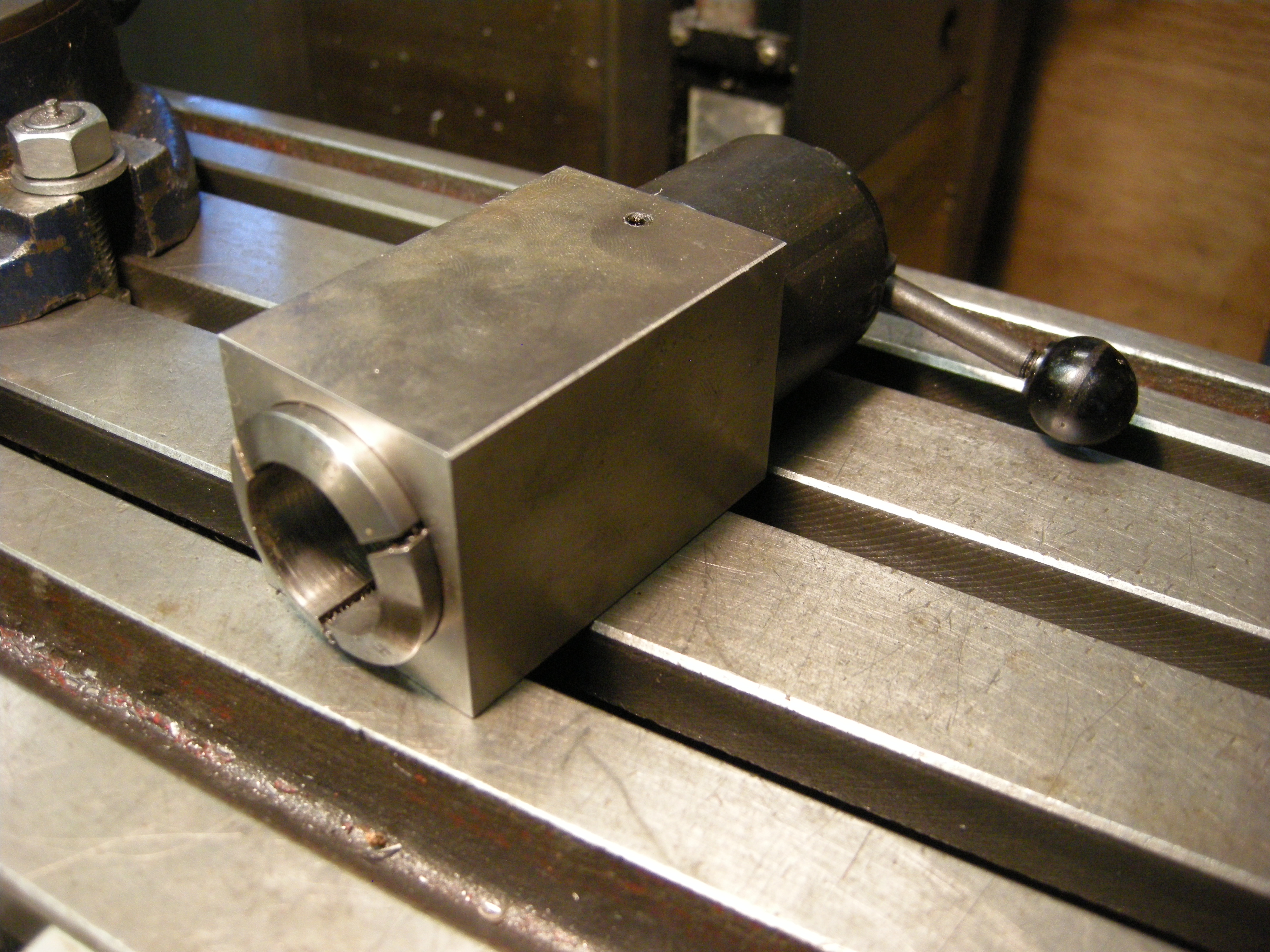
Collet blocks
One way of holding round and some other shapes – square and hexagonal is by using collet blocks.
Collet blocks used as rotating collets are covered elsewhere. Collet blocks are covered here because they are often used in vices where they are only rotated in a very simple way.
Collet blocks are blocks of steel designed to take a specific style of collet. One of the most common is the Hardinge 5C collet. Usually there are two blocks – one is square and the other is hexagonal. Since both have parallel sides either can easily be held in a vice though the hexagonal one might not fit well in some smaller vices. The collet block should be held in the center of the vice’s jaws.
112 collet block square with collet
Fig. Square collet block 112

113 hexagonal collet block
Fig. Hexagonal collet block 113
Fig. One way to hold a hexagonal collet block 546
The beauty of the collet block is that it turns a round shape, the collet, which can be hard to hold into a square or hexagonal shape, which is easy to hold. Of course, only the end of the workpiece can be machined but if the part in the collet is not needed it can easily be turned off in a lathe.
But the collet block can be used to do more than this. This is because the block can be rotated in the vice to give 90° turns with the square block or 60° turns with the hexagonal block. This allows for a very simple and cost effective form of indexing.
If a large number of bits are being machined by holding them in a collet then it can be useful to have a collet stop. In the case of the 5C collet this screws into an internal thread in the end of the collet. This ensures that each part in pushed into the collet by the same amount.
The only problem with this is that the position of the collet block laterally in the vice is not well defined. This can be done using a stop fitted to the collet is the case of the 5C type collet, or a stop fixed to the vice or a separate one bolted to the table of the milling machine.
Collet blocks for ER type collets
These work the same as the 5C collet blocks.
Fig ER collet blocks
One difference is that the closing nut is a larger diameter than the collet block. This can be got round by using short parallels to hold the collet block.
Fig holding ER collet blocks
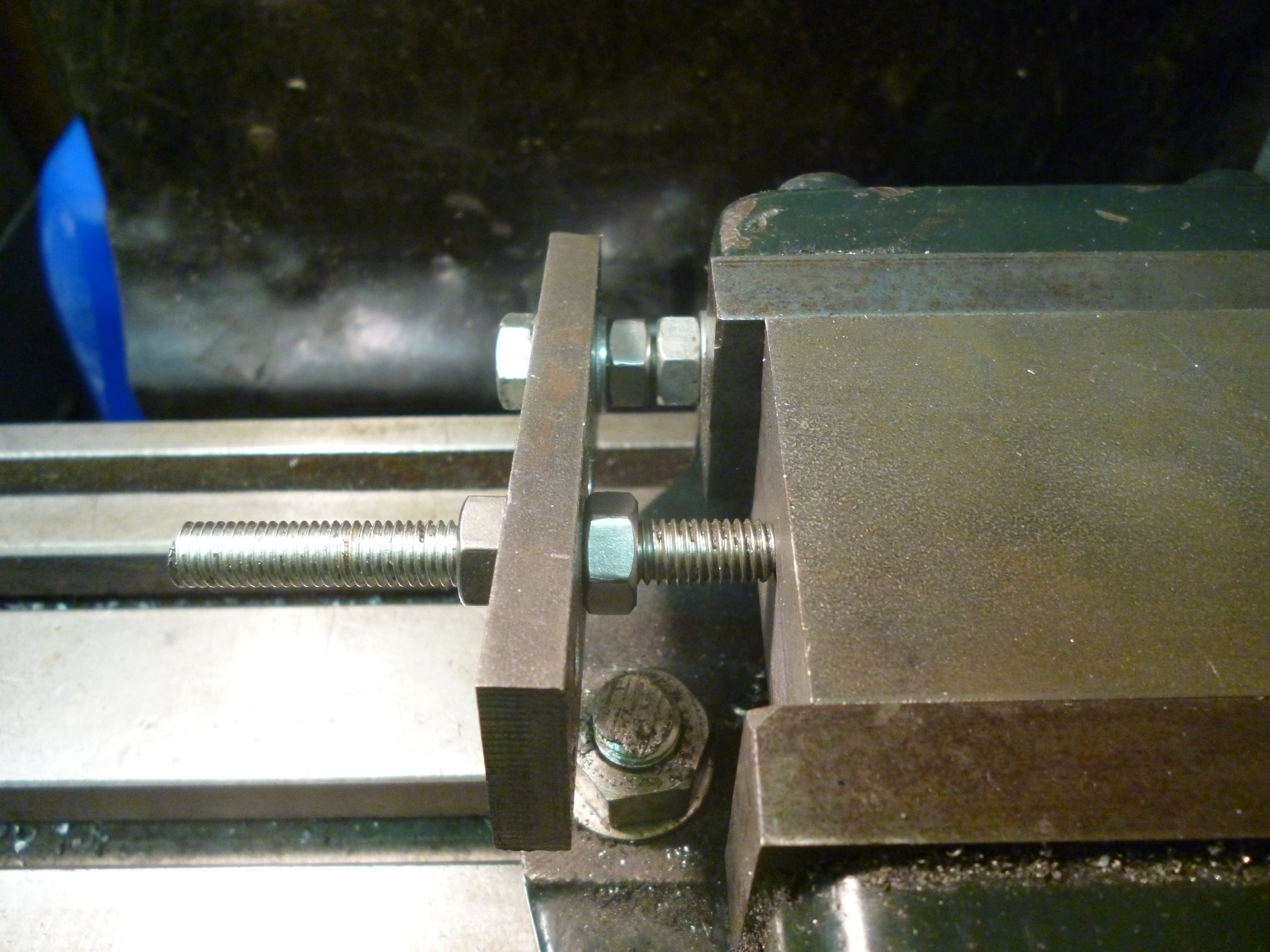
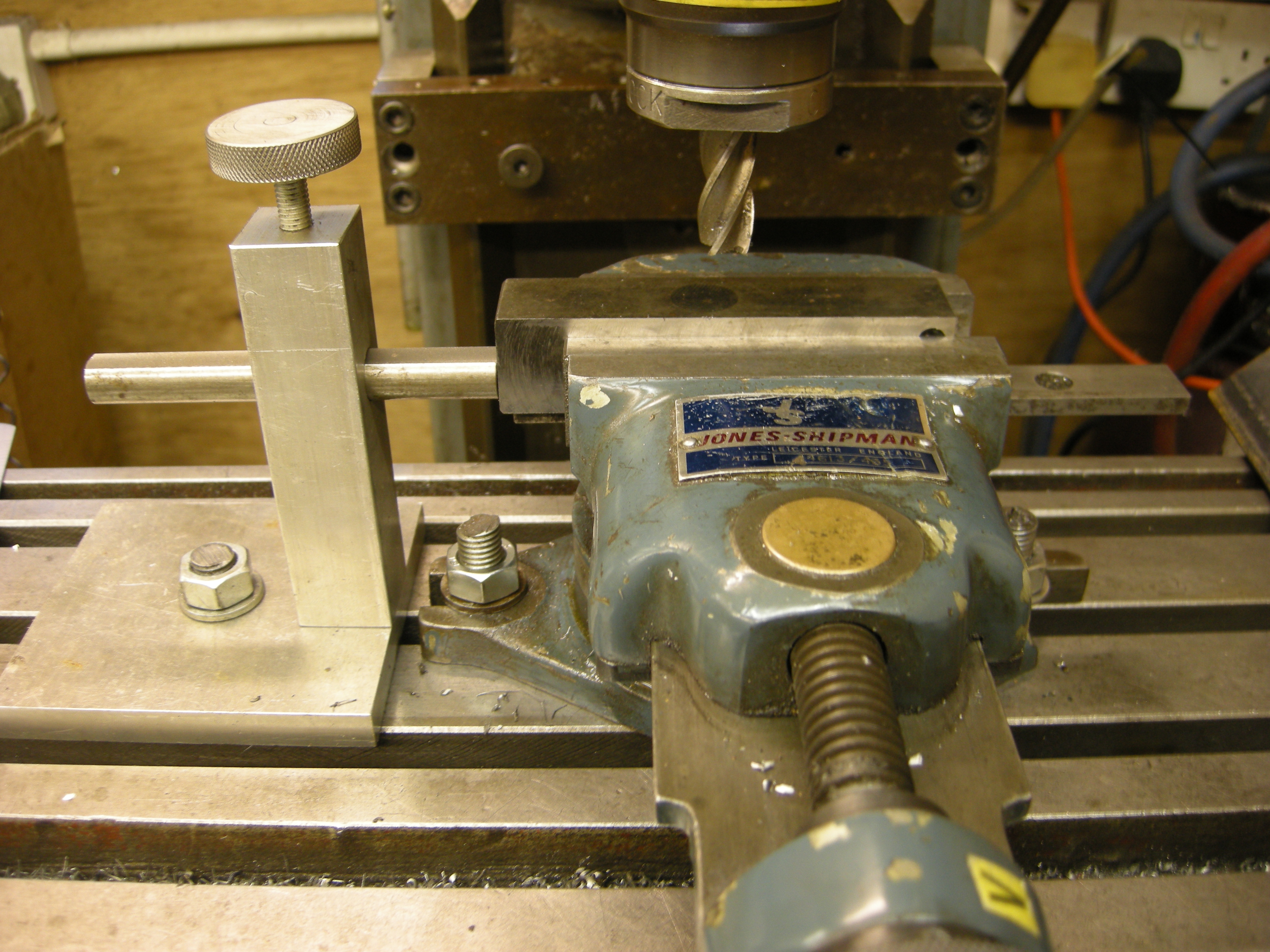
Holding studding
Studding can be held by making a square piece that has a thread matching that of the studding made exactly in the center of it. This piece is slit though one side. The studding is locked by means of two nuts locked at either end of this piece.

231 holding a threaded workpiece 1
It might seem that studding could be held using soft jaws. But, often, what will be found is that the studding rotates, very slowly, as it is being milled.
Vice in a vice
Often a very small workpiece cannot be conveniently held in a standard vice. One way round this is to hold the workpiece in a very small vice and then to hold this small vice in a larger vice. This could be useful where we needed to machine both ends of a workpiece but the workpiece was too narrow to stick out of both sides of the usual vice. The jaws of the small vice will be, of course, at 90° degrees to the first vice.

722 vice in a vice
Whatever properties the large vice has, for example, swivel, tilt etc all become to some extent, properties of the small vice. But allowance has to be made, for example, for the change in height of the workpiece and that it has been rotated by 90º.
Notes relating to all vices – Holding very irregular shapes
Where a workpiece had uneven surfaces, traditionally, two opposite surfaces would be filed till they were fairly flat and parallel to each other. It could then be held in the vice.
If the shape is not too rough it might be possible to hold it by putting pieces of wood between it and both of the jaws of the vice.
In this case the aim is not to machine it completely like this. The aim is to produce just enough of two flat surfaces so that it can be held without the wood in the vice.
Consider a very complex shape that has no surfaces with which to hold it in a vice. An example of this would be a small casting of a human body.
The solution to this to make a small box that can be held in the vice. The casting is fitted into this box and the empty space is filled. The filling can be a low melting point metal so long as the filler has a significantly lower melting point than the casting and the filler does not wet the casting or epoxy resin or plaster of paris.
Use of vices
Comparison with clamping
The main advantage of a vice compared to clamping is speed. The speed arises because for a large number of different jobs the vice can be used and the workpiece is held by just a few turns of the handle.
Clamps not only take time but most set-ups are only relevant to one particular job.
But on the other hand clamping will solve many different jobs that cannot be done in a vice.
In general if a job can be done with a vice it will be quicker. If it cannot be done with a vice it probably can be done using clamps.
Particular types of vices
The plain milling vice
The plain milling vice is the most useful of all the different types of vice available.
One of its advantages is that because of its simplicity it is lower than many of the other types. On small milling machines this can be an important advantage.
Plain milling vice – Machining long workpieces
Where the workpiece is too long but rigid enough to be machined it is often easier to hold it, horizontally, by supporting it on blocks on either side of the vice as shown.
fig
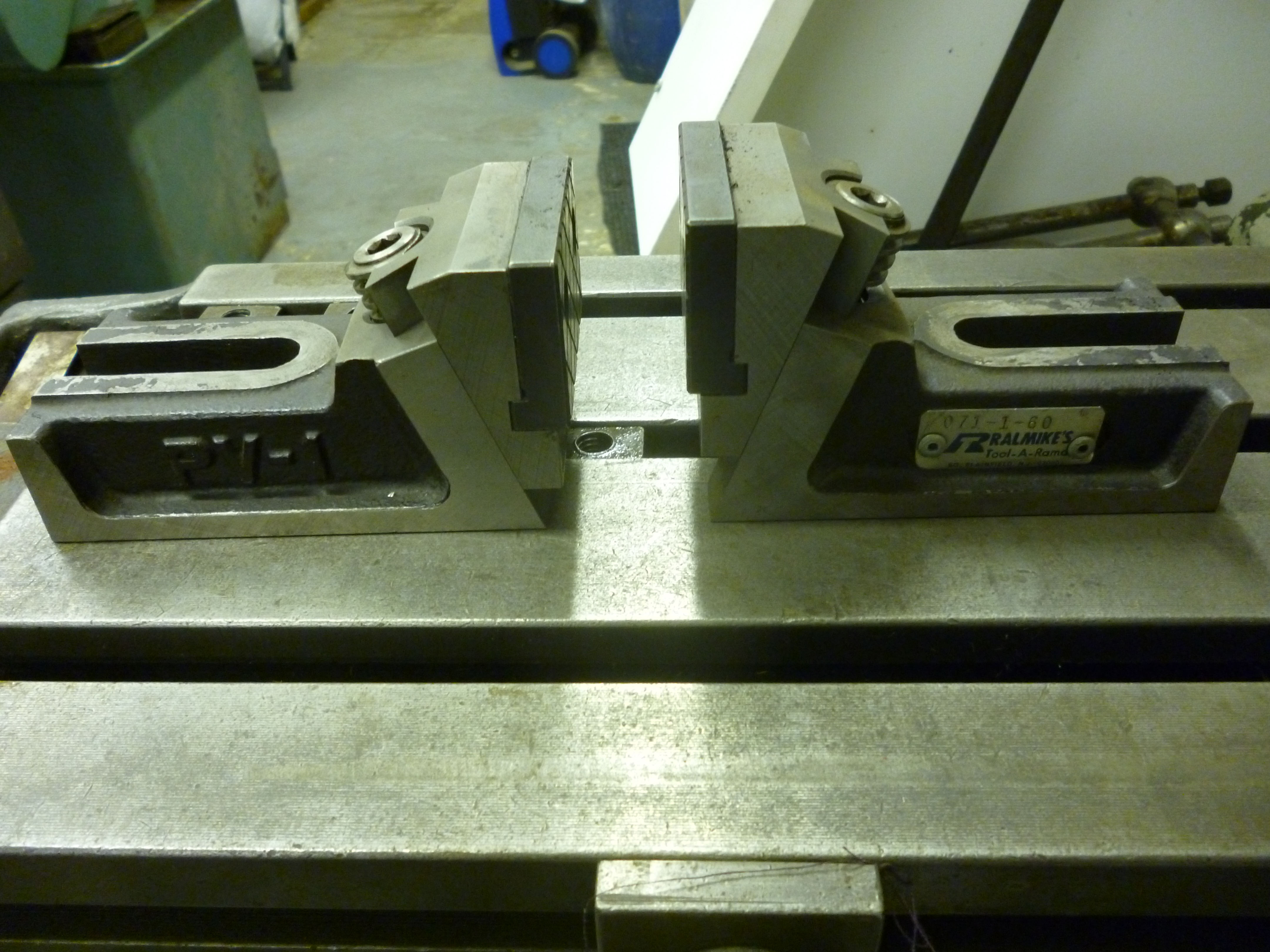
It is also possible to hold it more securely holding it in two vices mounted side by side. It is very convenient if the height of the bottom of the jaws of both of these vices is the same.
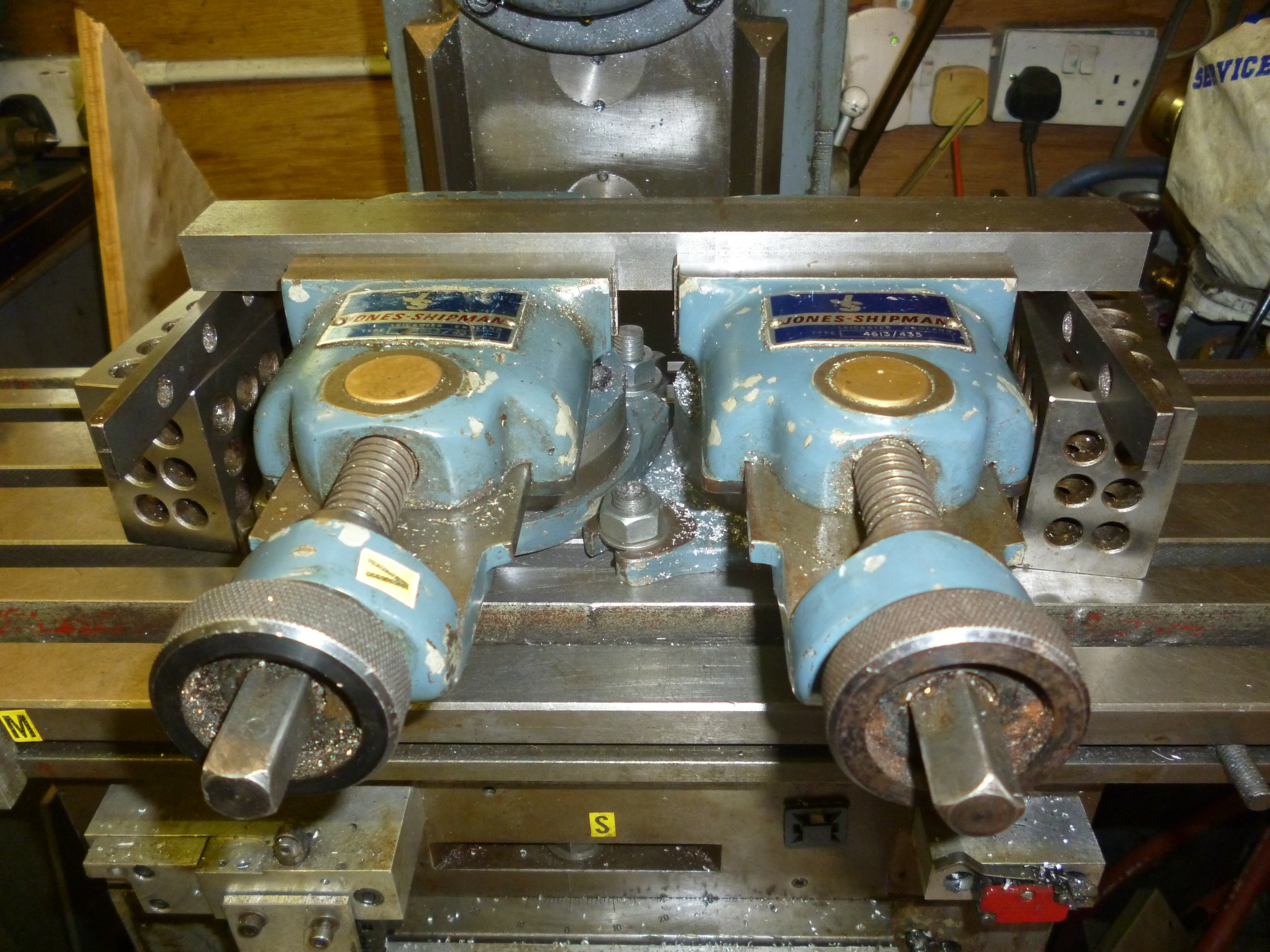
649 Using two vices
Fig. Using two vices 649
(the only pair of vices available were swivel vices.)
Even when two vices look the same it does not follow that the bottoms of both vices are at the same height. In this case the workpiece is actually resting on two 1-2-3 blocks.
A pair of vices has to be aligned so that the fixed jaws are in line.
However they must also be parallel to the milling table. Set one vice up and set it so it is square. Put the second vice near it loosely. Put a long parallel in the first vice and then tighten the second vice on it. The second vice will now be square and lined up with the first vice. Tighten it tightly to the milling table.
If this cannot be done then the first vice needs to be moved slightly and the whole process repeated till the second vice also fits.
Use of plain milling vice – Engine frames
One job best done on a milling machine is the machining of the horn blocks after they have been fitted to the frames of an engine.
The problem is that it is very desirable that the horn blocks are identical on both sides of the frame. Firstly the width of the space for each axle box must be accurate and the spacing between the spaces for the axle boxes must also be accurate.
One approach is to fit the frames together as they will be on the final engine. It is possible to use the buffer beams and any other spacers to do this. One alternative is to make some dummy spacers especially for this job. These are made to hold the two frames as close together as practical.
Alternatively, when the frames are finally assembled the horn blocks will be on the inside of the frames. But if the frames are swapped round the hornblocks will be on the outside. The frames can then be clamped together like this for machining.
It is now possible to machine the horn blocks so the width for each axle box is the same and the spacing of the axles is the same.
Often the length of the frames is far longer than the width of the vice. This does not matter. It is not going to introduce any errors if the frames, bolted together, are passed through the vice as needed to mill each pair of hornblocks.
In all cases it is essential that the frames are aligned to be parallel with the x-axis of the milling table. This can be done not using the bottom of the vice to align the frames but to use 1-2-3 blocks and parallels on each side of the vice to ensure the frames are horizontal.
Plain milling vice – head tilted
Cutting a keyway broach
Keyway broaches are often used to cut keyways in parts like gears that have to be fixed to a rotating shaft.
A common arrangement is for a section of soft tool steel, about 150mm long, to be made in a T-shape. The head of the T is to give it strength. It is the stem of the T that cuts the teeth. The teeth are like large saw teeth but also the cutting edge is on a slope so the first tooth cuts very little and the next a bit more and so on.

715 keyway broach
Fig. a typical keyway broach – 715
All of this can be made using a plain milling vice. The workpiece is held on a parallel so that the sides of the T can be cut away.
The workpiece is now refitted in the vice at a slight angle and the stem of the T is cut to give the required slope. It is kept in this position so the top of the stem of the T is horizontal.
Saw tooth shaped teeth are cut using a dovetail cutter held with the vertical head at an angle as shown.
Each cut will cut the rake of one tooth and, at the same time, the large clearance angle for the previous tooth. It can be seen from the drawing that if the dovetail cutter cuts with a 60° angle then if the rake is set to 2º then the large clearance angle will be 28º and the angle of tilt of the head will also be 28º. A second cut will be needed to make a first clearance angle of about 5º.
However, this will produce a cut with a sharp angle at the points where the broach is at its thinness. At the same time this component is highly stressed when used. This could be solved by grinding off the tips of the cutting corners of the dovetail cutter.

366 cutting a broach 3
Fig. 370 cutting the teeth on a broach 366
Fig. 371 drawing of the geometry of the teeth of the broach – 1020
This then needs to be hardened and annealed.
To use this broach it is necessary to make a bush that fits into the hole of the gear etc that needs the keyway. This bush has a square hole in one side of it. This holds the wide bit, i.e. the top of the T, of the broach but not the cutting teeth.
The broach is pushed through using some sort of press. It is usually necessary to cut the keyway in several passes. After each pass a filler of about 1.0mm thick is added to the space between the bush and the back of the broach.
Design of a broach
It is essential that at any time there are at least two teeth of the broach cutting the workpiece. But, large teeth are easier to cut and sharpen and make a bigger space for any swarf to accumulate in. Each tooth can be expected to cut from 2 to 4 thou per pass, that is, about 0.05mm to 0.10mm. The distance between the cutting edge and the start of the second clearance angle, the land, should be about 1.0mm.
Suppose the workpiece is about 10mm thick then the spacing of the teeth could be 4mm. If the broach is about 150mm long then it will have about 30 teeth. If a tooth can cut 0.05mm each then 30 teeth can cut 1.5mm.
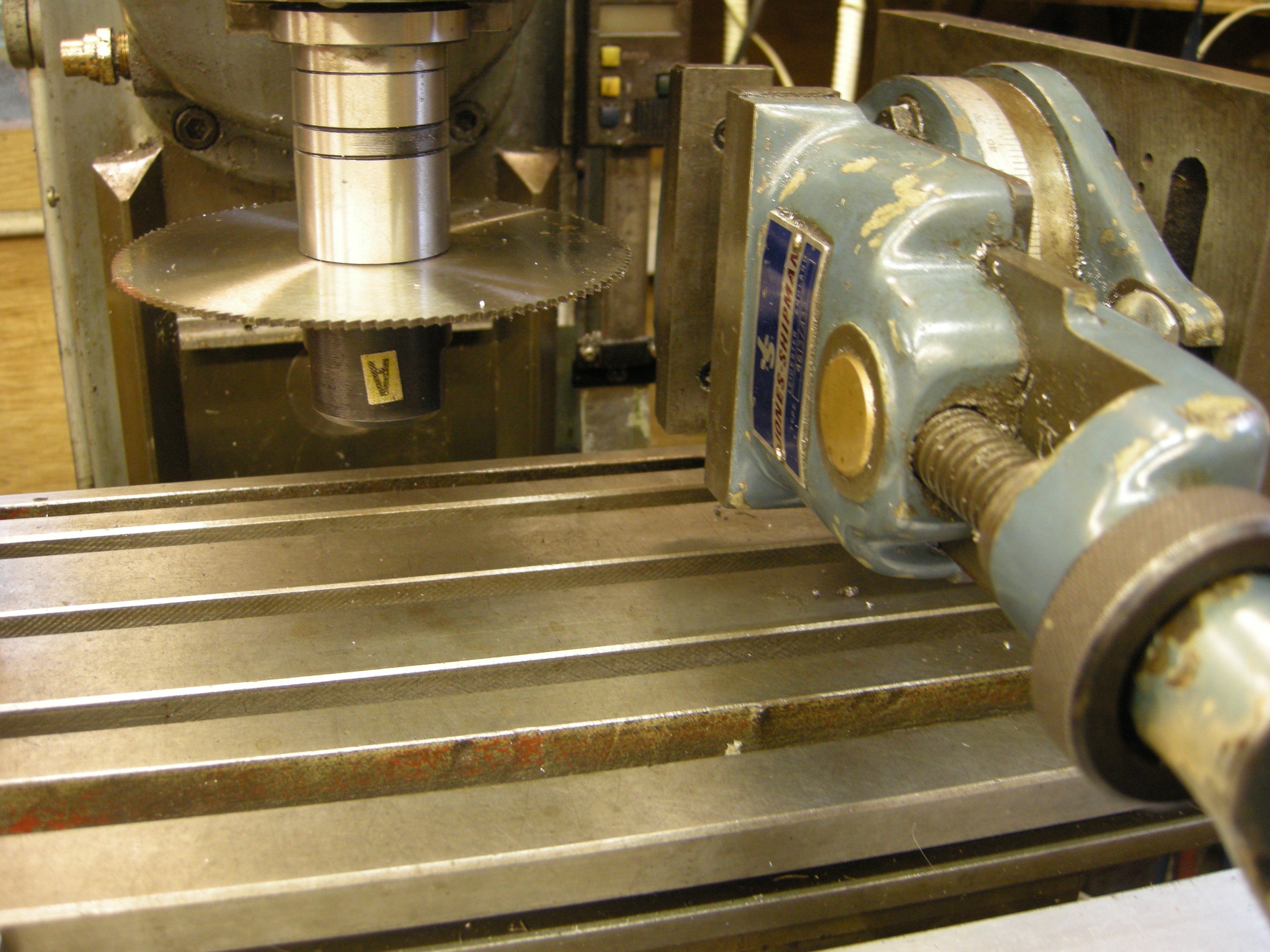
Use of plain vice – horizontal milling
This is one of the most common ways of using a horizontal milling machine. Since the arbor with the cutter is coming out from the column of the machine the cutter will be cutting in the x/z plane. The workpiece will get cut as it moves from left to right or, more commonly, from right to left.
If the face of the vice lies along the y-axis it is almost impossible for the workpiece to “slip” in the vice and so considerable force can be used to cut it.
In this situation is possible to use wide cutters such as a slab cutter with two face cutters on either side of it so that the top and two sides of a workpiece can be cut in one pass.

430 horizontal milling with a vice
Fig. Vice as commonly used for horizontal milling 430
Most of the larger type of vice that would be used for this will be found to have slots in the front and back positions so the vice will fit easily this way round.
Emulating horizontal milling
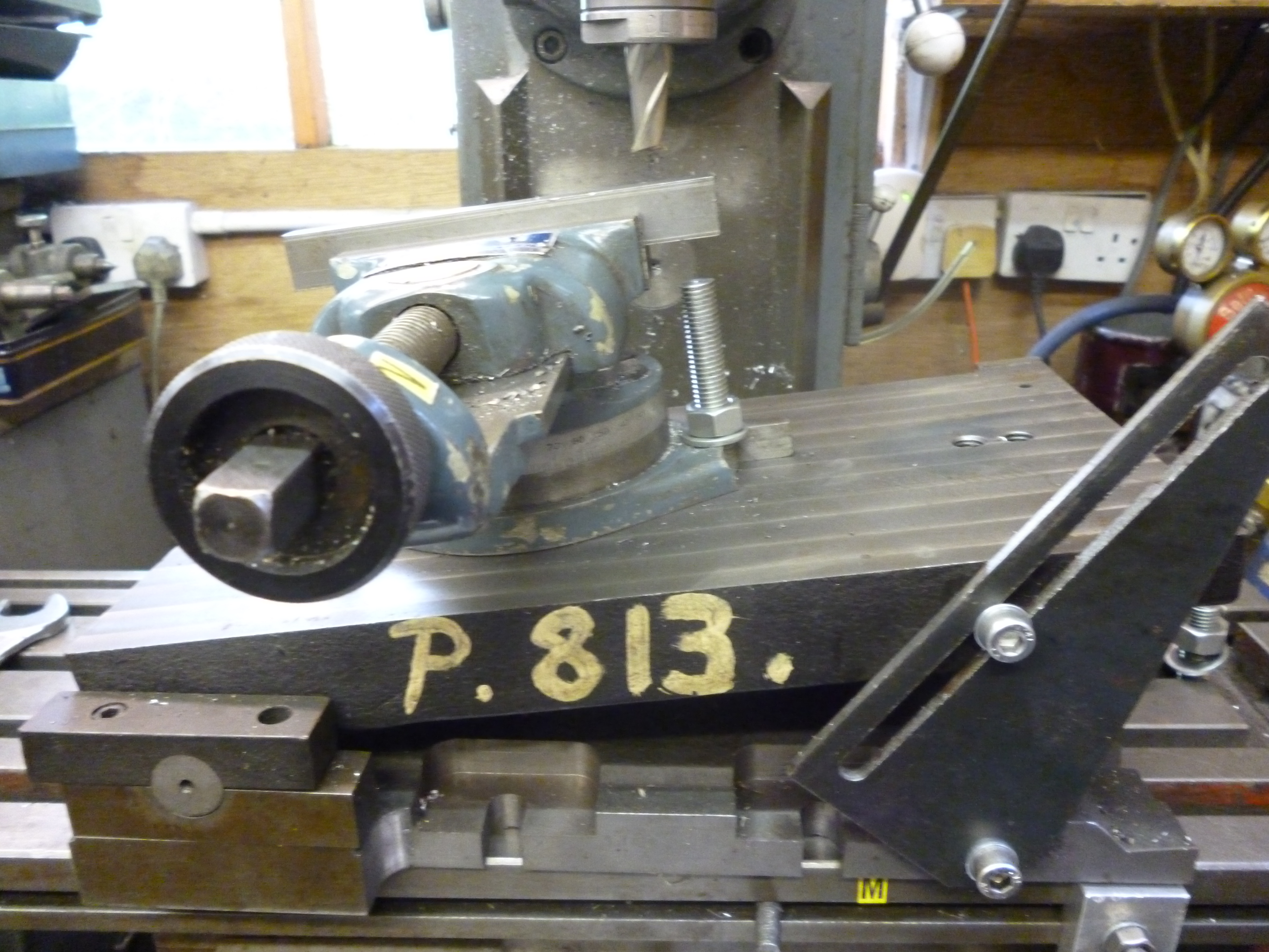
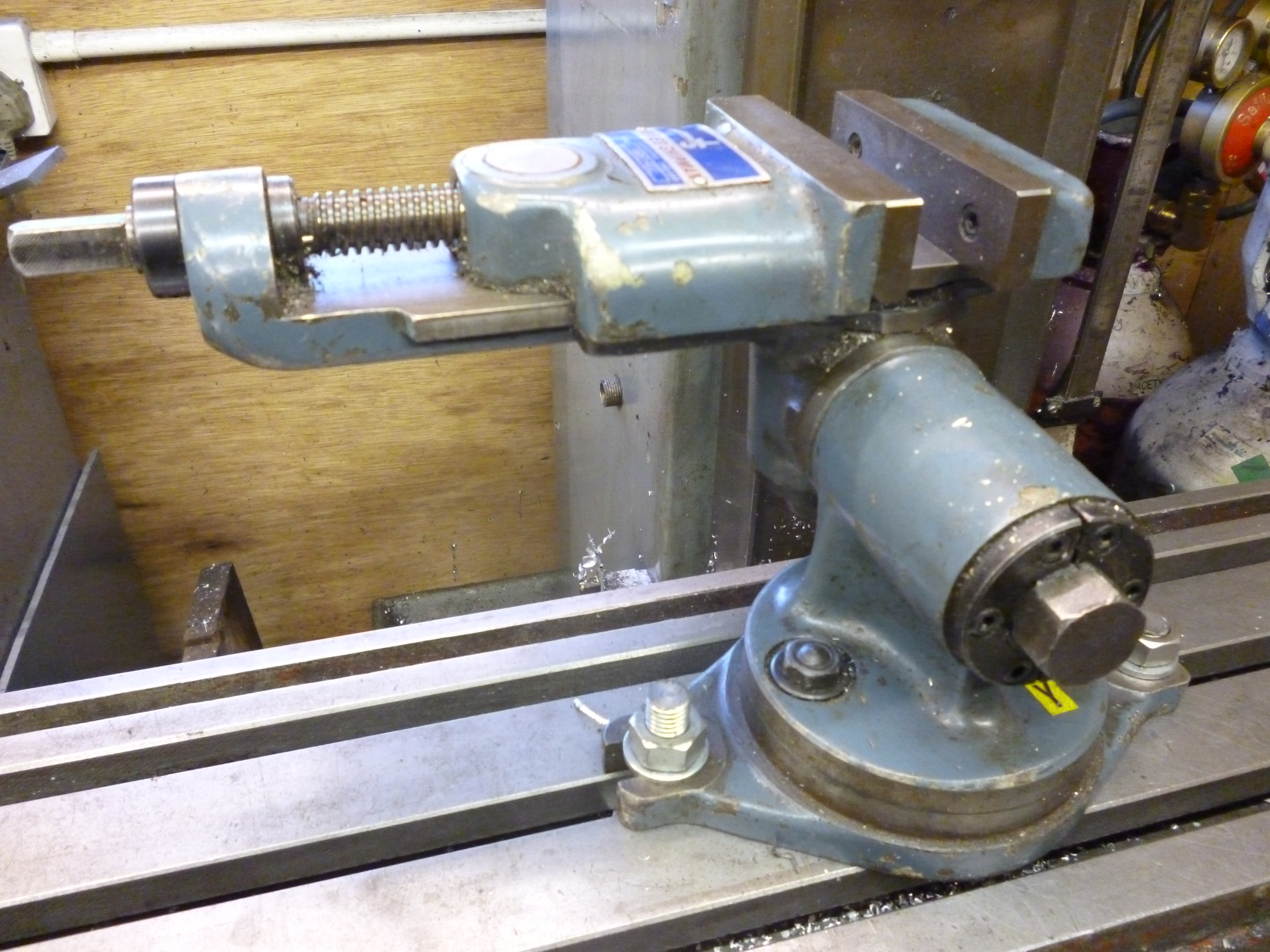
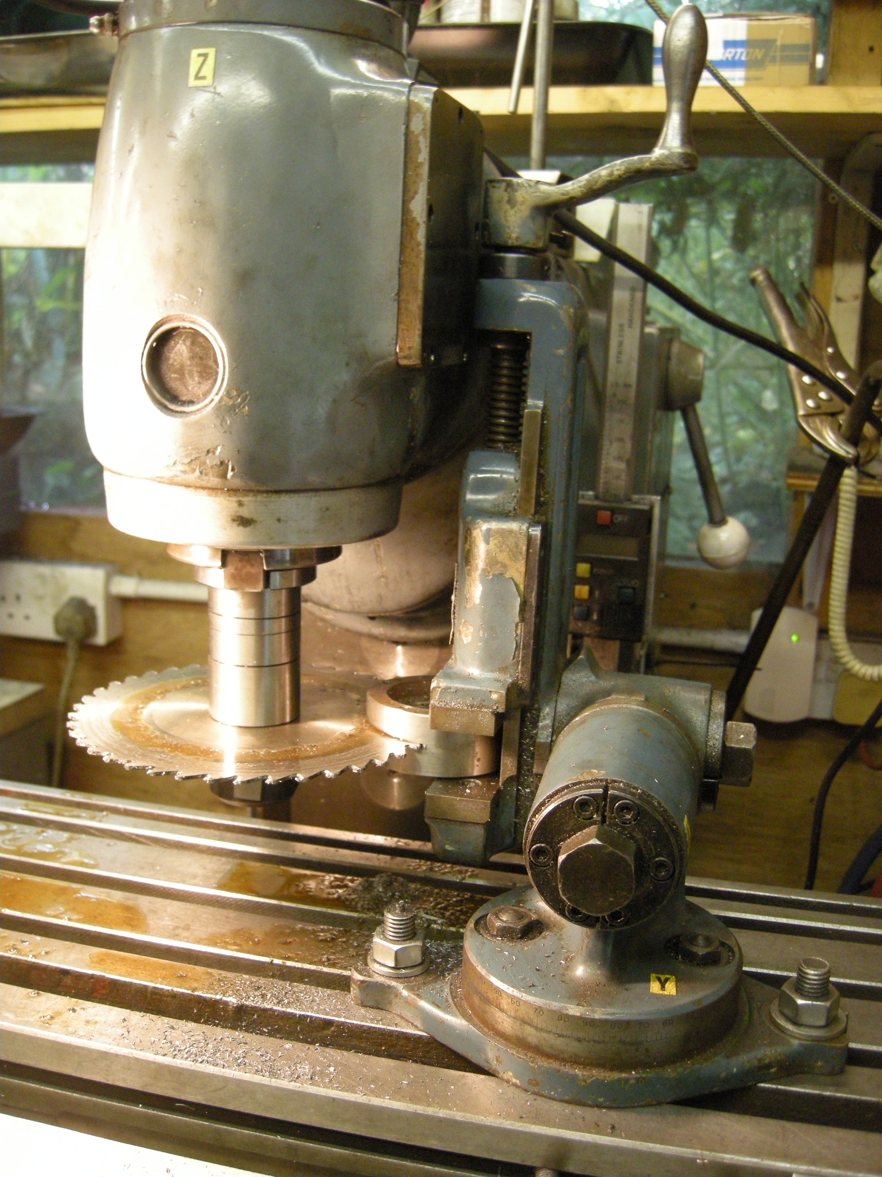
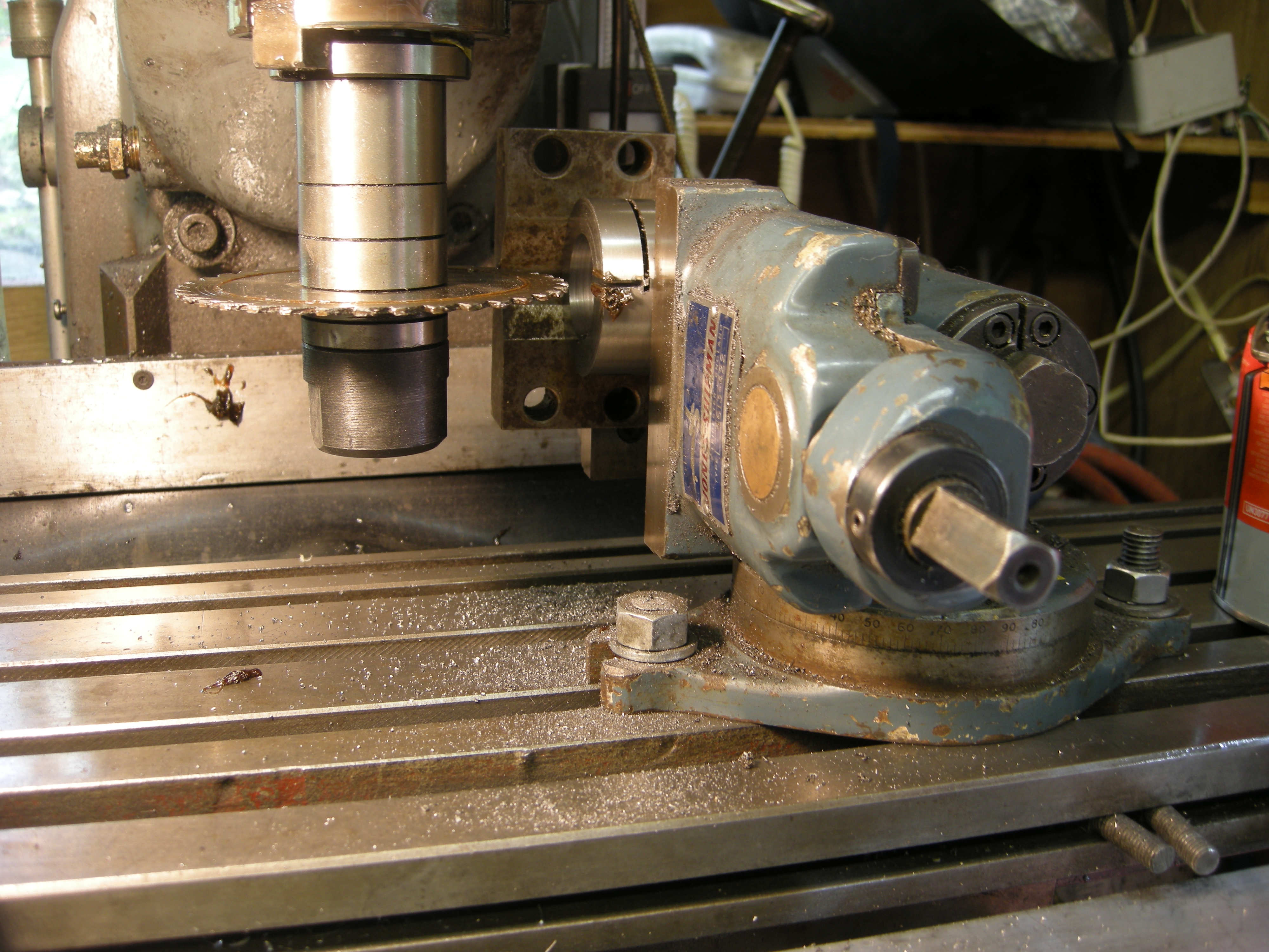
Plain milling vice mounted on an angle plate – Using a stub arbor
If the workpiece is held in a vice mounted on an angle plate and the cutter is held in a stub arbor held in the vertical socket then this combination emulates a horizontal milling machine with a vice mounted on the milling table. The vice jaws are at right angles to the cutter.
341 horiz on vert angle plate vice
Fig. Emulating a horizontal milling machine 341
(at the time of taking this photo there was not an angle plate big enough to take the plain vice.)
This setup is not as rigid as it would be if it was a horizontal mill largely because the arbor is not supported at the far end. Furthermore it is more difficult to setup the workpiece than if the vice was horizontal.
Of course the vice could also have its jaws horizontal. If the jaws are vertical the top of the vice is clear of the vertical head. If the vice is turned so the jaws are horizontal, what is now the top of the vice will clash with the vertical head.
One solution to this is to use cutters with a much larger diameter so that the vice is further away from the head.
In the following examples it can easily be seen that they are all examples of horizontal milling, i.e. a horizontal type cutter is being used but on a vertical milling machine.
Use of plain milling vice with stub arbor – Making a collar with one slit
A common component is the collar. This is simply a ring that can be clamped to a round shaft.
It can either be a straight round ring or it can have tags on the side of the ring. The clamping action can be done by a bolt that is completely in the width of the ring or by a bolt going through the tags.
In either case the ring has to be split. In the first case, anywhere round the ring, or in the second, by slitting through the tag.
If it is a plain ring, it can be turned on the lathe and a hole drilled and bored on the lathe. The bolt has to be held within the width of the ring. This means that the ring has to be countersunk to take the head of the cap screw. The ring is then slit by holding it in a vice and then slit with a slitting saw held in a stub arbor.
Very often when this is done the ring closes up and if it is slit all the way through it will clamp the slitting saw and this will probably break.
The way round this is to cut it almost all the way through. Then remove it from the vice and cut what is left using a hacksaw.
The hole will now be very slightly too small. It can be enlarged by using a piece of shim that just fits the slit as it is now, mounting it in the lathe, and reboring it to enlarge the hole to the original size.
Fig. slitting a collar one way
Fig. slitting a collar the other way
Plain milling vice on an angle plate – head vertical – vertical mode
Cutting a rack
As we have already seen, if we wanted to use a horizontal cutter but we only have a vertical spindle, the usual solution is to mount the cutter in a stub arbor. The workpiece is mounted in a vice held on an angle plate.
Fig. 376 cutting a rack 681
Clearly the length of rack that can be cut like this is limited due to the workpiece hitting the body of the vertical head. In this case it is about 50m. But it is possible to cut the rack from the middle of the workpiece to one end and then turn it round and cut it to the other end. This would give 100mm.
Plain milling vice mounted on angle plate with boring head
Round to flat adapter
This combination is very useful for cutting out cylindrical shapes from rectangular ones. In practice it is often easier to hold the workpiece in a vice clamped to the angle plate than to clamp the workpiece on the angle plate.
An example of this would be the base for a smoke box. But this is just one case of a component that allows a round shape to fit against a flat surface.

419 round to flat adapter 2
Fig. Machining a round to flat adapter 419
Usually, when boring a hole it is easy to measure the size of the hole and increase the radius of the boring head as required. In this case there is only part of the hole. The easiest way get round this is to set the cutting diameter of the boring head first.
see – setting the outside cutting diameter of a boring head
The boring head then needs to be centered with respect to the workpiece. With the tip of the cutter above the end of the workpiece it should be possible to find a position where the tip of the cutter is just above one corner of the workpiece and then the other. When this is the case the center of the workpiece is aligned with the spindle, i.e. the axis of rotation of the boring head. At this point the y-axis can be locked.
The workpiece can be moved away from the boring head till, when the cutter is lowered so it just touches the workpiece, it just snicks it. The workpiece is raised as it is being cut. Then the workpiece is lowered, fed towards the cutter and the whole cutting cycle repeated till the job is finished.
Drill vices
It will be seen that milling vices have one very long movable jaw. This is ostensibly to ensure that it cannot tilt even very slightly from one side or the other.
A drilling vice does not have such a long movable jaw and it would seem that allowing for its lack of robustness if the workpiece is held in the middle of it, it can be used quite satisfactorily on a milling machine for light milling.
Its main merit is that it is much cheaper to produce and, hence, to buy.
Toolmaker’s vice
This is just like an ordinary vice except it is generally more accurate. They are often designed for use on grinding machines where magnetic chucks hold them. They often do not have any easy way to clamp them to the table. Some have slots along the sides that can be used to clamp them.

207 toolmakers vice
They can be useful on a milling machine because they can come in very low profiles or very narrow widths. This may allow them to be useful when space is at a premium.
Unless the extra accuracy is needed it does not do any more for you than an ordinary vice would with a lot less trouble.
The rack vice
A rack vice can be used to hold a workpiece that is too wide to fit in an ordinary vice. However in some cases a workpiece like this can be machined just as well by clamping it to the table directly or on parallels.
This can be an easy way of holding a workpiece so the whole of the top surface can be milled.
The rack vices made by Jones and Shipman have faces that have a rough finish and are made so that as they are forced against the workpiece they force it downwards. These vices are designed to get the bottom surface of the workpiece hard down onto the bottom of the vice. The only way of being sure of this is if the bottom of the workpiece touches the bottom of the vice or something else that is parallel to the bottom, i.e., a pair of parallels.

9 rack vice
The force pulling the workpiece downwards is so great that if parallels are placed underneath it, it becomes impossible to pull them out. It is almost impossible to set an edge of the workpiece to be vertical or any other angle if this conflicts with the bottom of the workpiece touching the bottom of the vice.
If the workpiece is tall and the cuts are heavy it is possible for the workpiece to come loose in completely unexpected ways using this sort of vice. It is caused by one or both jaws slowly working their way downwards. It will happen very slowly. If this happens it will be noticed that the workpiece slowly creeps sideways in the vice. Unless machining stops immediately the workpiece will come completely loose.
This is caused by hard, intermittent cutting action. It is easy to show. Fit a large piece of metal into the vice. Screw it up tight. Bang it on the side with a mallet 6-12 times. It will slowly loosen and will become more and more loose till it is completely free.
The best thing to do with these is to removed the screw and springs in the jaws and fit the jaws back in so they are completely rigid.
If the workpiece is simply held between the floating jaws, the vice can be properly tightened. This will happen when both of the jaws have been pushed to their lowest possible position.

426 machining a wedge
Fig. 380 Using a rack vice to cut a tapered surface 426
On the other hand if a workpiece is held on one side but not the other the jaws will move down move on one side than the other and the workpiece will only be held properly on one side.
Fig. Rack vice – uneven jaws 412
In this photo the workpiece is meant to be tilted but the jaws are not.
Squaring up
The rack vice is ideal for squaring up. This is the process of making a block of metal with all of the sides square to each other. This is partly because it is likely to be the vice with the biggest opening.
When machining a large surface it is always best to be able to machine it in one pass. If it is small it might be possible to use a face cutter. If not then the best option is a fly cutter or a boring head being used as a fly cutter.

715 cutting a surface using a rack vice
Fig. machining a surface using a rack vice and a boring head 715
This is a fundamental process. Many components can be seen as being made from something that started life as a block of metal. A block simply has 6 sides, all of which are at right angles to each other.
The part is then cut out from this rectangular shape. Many other parts can be seen as being cut from a cylindrical shape such as wheels and cylinders. These are best squared up on the lathe.
Since the whole surface of each of the sides needs to be machined, usually, the easiest way of holding the workpiece is by using a vice. It might seem that a block with six sides will involve turning the block so that each side can be machined in turn. However it is easy to see that, if done properly, it is possible to machine three sides at one setting. It then needs to be turned, only once, to machine the other three sides.
Of course to machine three sides in one go means that the whole of each of the three sides must be completely clear for the machining. The key to doing this is to mount the work piece on parallels and with parallels at either end holding the work piece clear of the jaws.

295 squaring up a block
Fig. Squaring up a block 295
The top surface is cut in one pass using a face cutter or fly cutter. The sides are cut using an endmill. In the example shown the parallels are needed at either end because the sides of the workpiece do not reach out beyond the sides of the vice. Similarly the workpiece is raised up so the end mill will not touch the bottom of the vice.
After the first three surfaces have been cut the workpiece is turned over and rotated through 90°
The only assumption, given the workpiece is firmly held down parallel to the bottom of the vice, is that the bottom is flat and parallel to the milling table. All of the right angles produced are dependent upon the vertical head being at right angles to the milling table in both the x/z and the y/z planes.
see setting the vice parallel to the milling table
Two part vice
A two part vice is really a variation on the side clamp. It usually has one fixed clamp and one adjustable. The benefit of this is that it can hold workpieces that are far wider than can be held by any other vice, even the rack vice.
644 two part vice
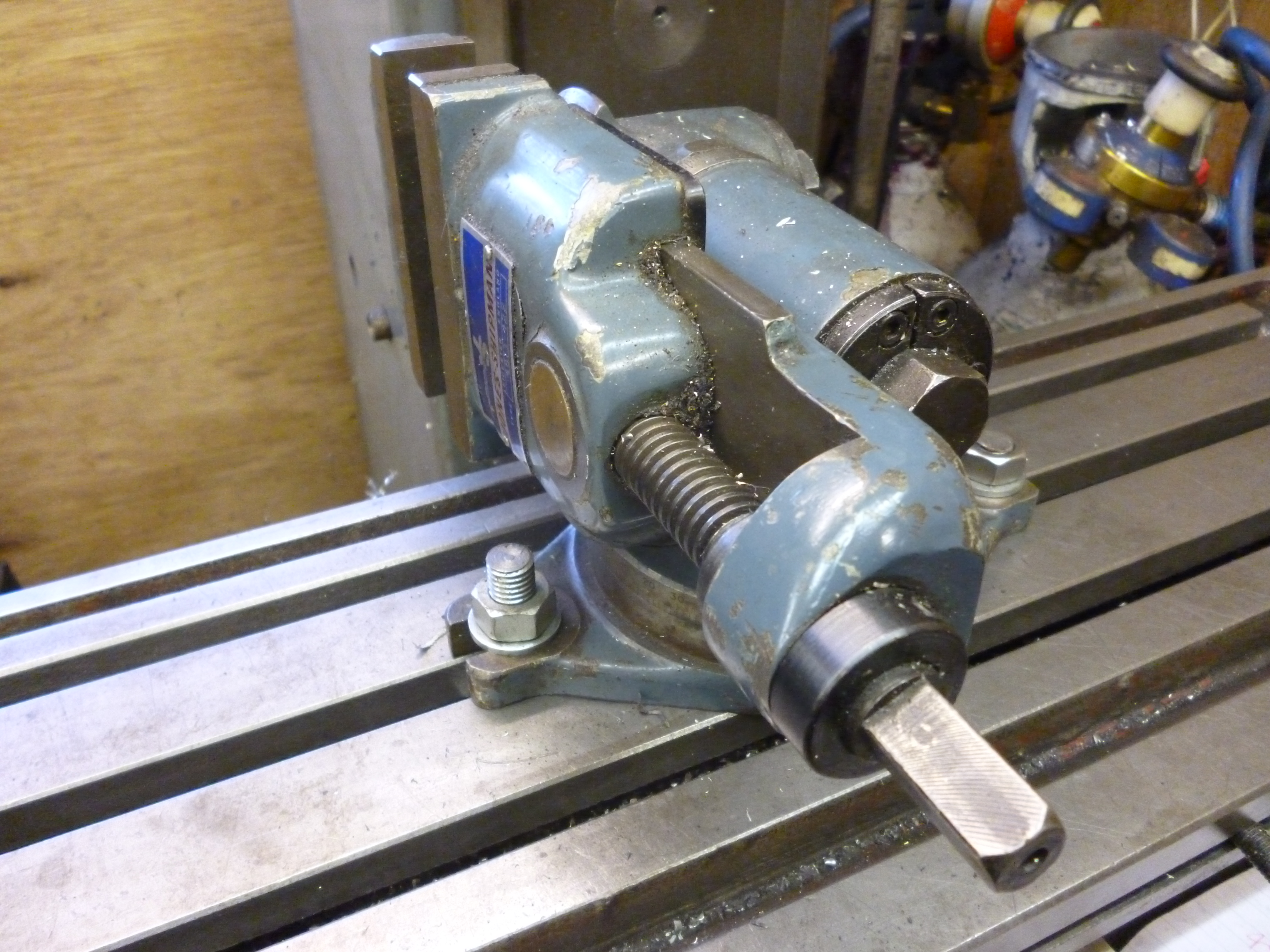
Swivel vice – intro
A swivel vice is useful for making it possible to make cuts at one angle on a workpiece and then making other cuts at an angle to the first. This is the most obvious use but there is another class of uses. These are where the jaws of the vice are probably parallel or at right angles to the milling table but, for one reason or another, it is useful to be able to swivel the base in order to make it possible to clamp the vice onto something.

4 swivel vice
Fig. A swivel vice 4
Aligning a swivel vice
A swivel vice should first be set to zero by its own scale. It can then be aligned as for a plain milling vice.
see Aligning a vice at an angle
Cuts can be made like this and then it can be rotated using its own scale. This scale is often graduated only to one or two degrees. So you would be lucky to get the angle any better than about a fifth of a degree using this. The value of this feature can easily be over estimated.
Swivel vice – making cuts at different angles with head tilted
Making an ellipse
In the following figure a swivel vice is being used to cut an ellipse by cutting a piece of round material at an angle. The part shown below was made to hold a partially mirrored surface at 45° in a brass tube. The shape is an ellipse. The first cut cuts the surface on one side. The second cut cuts it off.
Fig. Cutting a tube at an angle 539
If cutting at 45° was all that mattered it might seem any vice could do this. But it is easy to see that in this case the problem would be clamping the vice. With the swivel vice this is not a problem.
Fig. Elliptical part 527
Swivelling vice on an angle plate
In the figure the angle plate has had the slot widened at a most inconvenient place. However the swivel vice has been fitted with its base at an angle so it can be securely clamped. However, because of the swivel feature, the jaws, on the other side, are vertical as required.

420 advantage of swivel vice
Fig. Swivelling vice on an angle plate 420
A plain milling vice, which does not swivel, may be difficult to clamp at odd angles because the slots on the vice might not match the slots on the table. A swivel vice gets round this problem.
Tilting vice
The most common vices that tilt, tilt in just one way. They tilt in the front/back direction, not left/right.
If precision is necessary a protractor must be used. The protractor must be at right angles to the face of the jaws when measuring the angle of the tilt.

640 tilting vice
Fig. tilting vice 640
Simulating a tilting vice
A tilting vice can be simulated by using a tilting table with a vice mounted on it. The tilting table must be aligned first. Then the vice must be aligned with the table in the horizontal position. Then the table can be tilted.
594 vice on tilting table
Fig. Swivel vice on tilting table 594
This arrangement can be used to simulate a left/right tilt or a front/back tilt.
Tilting vice – compound angles
Though the tilting vice might only tilt in one plane it can be used to machine compound angles. This is done be holding the workpiece at the second angle in the vice. The resultant angles can be found using the table XXX in the appendices.
Sine vice
A sine vice is really just a tilting vice that tilts in the front/back direction. It can be used to make a very accurate angles.
Fig. – sine vice – xxx
But, again, this is useless unless the vice is accurately aligned when it is in the horizontal position.
Setting the angle on a sine vice
The sine vice works like a sine bar. A stack of slip gauges is put underneath it to set the angle. Since the distance from the point about the vice tilts to the point the slip gauges are in contact with is very accurately set, the angle can be computed.
The length between the axis of rotation and the roller is a fixed length. This is the hypotenuse of a right angle triangle. The height of this triangle is the height of the stack of slip gauges. The relationship between these and the angle α is:
Sine α = opposite (height of the slip gauges)
Hypotenuse (length from axis to roller)
See sine bars and slip gauges
A sine vice might be metric or imperial. Consider the common one made by Jones and Shipman. To be able to make very small angles would require a stack of slip gauges with a smaller height than that of the thinnest slip gauge. But the vice is constructed so the with no slip gauges it tilts slightly below the horizontal. To be horizontal it needs a slip gauge of exactly 0.100 inches thick. It is then easy to make up any size bigger than this. So for whatever height is required 0.100in has to be added to this.
Swivel and tilt vice
A swivel and tilt vice can be useful as a swivelling vice or as a tilting one. But in order to be able to do this it is much higher than a plain vice.

10 swivel and tilt vice
Fig. Swivel and tilt vice 10
Swivel and tilt vices usually have the swivel next to the table of the milling machine and then the tilt. They usually have the tilt feature tilting in the front/back direction rather than the left/right direction. It may not be immediately obvious but the two are not variations of the same thing but are fundamentally different.
If we have a swivel vice with a front/back tilt then, if the vice is rotated through 90º, the front/back tilt remains a front/back tilt.
Many workpieces are much longer than they are wide. Very often we want to cut a long edge at an angle. We can do this by using the front/back tilt but not the left/right tilt. If the workpiece is squarish in shape we can do this to one side and we can rotate the workpiece in the vice and do the side at right angles to it.
Swivel, tilt, and tilt vice
These vices have a swivel followed by one tilt, front/back then another tilt, left/right. This is, of course, equivalent to a swivel, left/right tilt followed by a front back tilt.
Fig. swivel, tilt, and tilt vice
The left/right tilt allows for a long workpiece in the vice to be tilted so that the workpiece has the end at the top. If the area of the workpiece is small it is possible to machine when it is horizontal with an endmill using the flutes of the endmill to do the cutting. When the area is large then this is much better because it can be cut, in several passes using the end of an endmill.
Fig. machining the end of a bar
Swivel, tilt and swivel vice.
A common swivel, tilt, swivel vice is that which used to be made by Jones and Shipman. These are easily available on the Internet for very modest prices. Everything here will refer to one of these.

x477 swivel tilt and swivel 1
Fig. Swivel, tilt and swivel vice 477
They were probable designed not for milling but for grinding tools bits. It is very good for holding a piece of HSS and grinding it so that it has three faces at various angles to each other. The angles are not computed but are measured as we move the swivel and two tilts until we get the angles wanted. For small jobs they are quite suitable for using on a small milling machine though they are not as rigid as a conventional vice. They also take up more of the height on the milling table.
Any of the combinations of swivel tilt and swivel can be used but they have to be used in the order they come on the vice. (In each case the unused variation is in “neutral”.) If the tilt is turned through 90º then the final swivel which would otherwise be in the horizontal plane now becomes a “tilt” in the vertical plane.
This vice can be seen as having three axes of rotation. The first is the swivel at the base. The second is a horizontal axis that does the tilt. And then the third is a swivel on the part that tilts.
Swivel, tilt and swivel – the problem
It is quite possible to set this vice up so the jaws are aligned, for example, horizontally along the x-axis. But there might be a 30° swivel one way on the first swivel and a 30° swivel the other way on the second swivel.
If the vice is tilted, now, the position of the workpiece is necessarily where one might have expected it to be.
If the vice is set up so the tilting axis is at right angles to the milling table then, if the workpiece presented a surface of a square bar to start with, it will now present the end of the square bar, still aligned with the side of the bar which is now facing vertically.
Alignment of the swivel, tilt and swivel vice
All three movements of this vice are calibrated. For many purposes these are good enough.
The alignment problem here is the horizontal tilt axis. It is possible for the jaws of the vice to be lined up vertically and horizontally yet not be correct. In the figure the first swivel is at 20° but the top one is at 20° the other way.

612 problem with the swivel, tilt and swivel vice
Fig. The problem when aligning a swivel, tilt and swivel vice 612
It does not appear to be easy to set the vice up so the axis of the tilt is perfectly at right angles to the milling table.
This is further complicated by the nature of the tilt and second swivel joints. They are both made with tapers. They both have a useful feature whereby the taper is forced apart if is is unscrewed far enough. But the other consequence of his is it is very difficult to adjust these joints precisely by tapping with a soft headed mallet.
The problem lies around getting the horizontal axis at right angles to the milling table.
1 set the bottom swivel to zero.
2 set the top swivel to zero
3 rotate about the horizontal axis till top surface of the jaws is vertical
4 rotate the top swivel till the inside surface of the jaw is vertical
5 rotate till the top surface of the jaw is horizontal
6 rotate whole vice till the inside of the jaw is parallel to the milling table
Use of a swivel, tilt and swivel vice
With this vice the jaws can be set at any angle in any plane or at any angle to any plane. A good idea of what can be done can be seen by looking at all the simple permutations. The top of the jaws is taken as the datum.
In most cases the height of the vice is greater than that of a simpler vice. In general it is less rigid than that of the equivalent simpler vice.
Case A – Top of jaws in x/y plane – jaws along x-axis
In this case the vice behave just like an ordinary vice. But it is much higher.

477 swivel tilt and swivel 1
Fig. Tops of jaws in x/y plane jaws along x axis 477
Case B – Top of jaws in x/y plane – jaws along y-axis
In this case it is the same as a swivelled vice turned through 90°.
479 swivel tilt and swivel 3
Fig. Top of jaws in x/y plane jaws along the y axis 479
Case C – Top of jaws in the y/z plane – jaws along the y axis
With a stub arbour in the vertical head, this is equivalent to a horizontal milling machine fitted with a plain vice. The jaws are in line with the cutter.
265 slitting collar 2
Fig. Top of jaws in the y/z plane jaws along the y axis 265
use of swivel, tilt and swivel vice
jaws in y/z plane along z axis
Case D – Top of jaws in the y/z plane – jaws along the z axis
478 swivel tilt and swivel 2
Fig. Top of the jaws in the y/z plane jaws along the z axis 478
Case D – example 1
One use of the swivel tilt and swivel vice is to set it up so the jaws are vertical. This can be used to hold long, thin workpieces “on end” so the end can be machined.

512 sts used to mill end of bar
Fig. Machining the end of a workpiece 512
Case D example 2
If the cutter is a horizontal one on a stub arbor in the vertical socket then this is equivalent to horizontal milling with the vice the usual way round.
342 horiz on vert tilting vice vert jaws
Fig. “horizontal” milling 342
It is quicker than using a vice mounted on an angle plate.
Case D – example 3 – boring an Int. 30 taper
In this example the vice is swivelled so that it can be used to hold a boring tool in the vertical position. This is being used to bore a Int. 30 taper. This results in a hole that is parallel and exactly coaxial with the axis if the taper. Notice the hole will only be parallel to the axis of the spindle if the vertical head is aligned so the axis of its spindle is at right angles to the table (in both the x/z and y/z planes).

633 boring a int 30 taper
Fig. Boring a Int 30 taper 633
Case D – example 4
Making a round to flat adapter
The swivel tilt and swivel vice can be a quick way of making a round to flat adapter.
Fig. 410
Case D – machining a rack
Machining a rack
If the workpiece is held vertically in the vice and a suitable cutter is mounted on a stub arbor this setup can be used to cut a rack. This is really just a variation on using a vertical machine as a horizontal machine.
This is odd in that the height of the vice is actually an advantage.
Fig. cutting a rack
The details of cutting a rack can be found at:
see calculations for cutting a rack.
The main limitations of this method is the length of the rack that can be cut.
Top of jaws in the x/z plane
Variations on this are of little interest because of the difficulty of seeing what is going on. Furthermore there is nothing that can be done with these variations that cannot be done some other way.

hi nice advice about vices, i just got a jones and shipman of ebay paid £65 for the vice has a repair at the bottom of the base and no handle, i can make one will arrive this week some time. going to use the vice on my metal shaper and small horizontal milling machine, i only take small cuts. not had much luck with the milling machine the 1 inch flat belt keeps slipping i get it to run right one day all the best Genyk
Thanks
john f
Try using some powdered resin on your belt it will improve its grip.
Thank you
john
how can i raise height of vise to get closer to mill chuck thanks
This is not usually a problem. The problem is usually a lack of height.
however, in your case, the solution is to make a plate roughly the shape of the bottom of your vice and sandwiched it between the table and the vice.
A long time ago I bought a hofman rotary table which had a dividing device the bottom of which was lower than the bottom of the rotary table. The previous owner of this had made a plate out of steel about 2 inches thick that fitted between the milling table and the bottom of the rotary table this meant the rotary table could now be installed anywhere on the milling table.
john f