go to “Milling – workholding”
Sub-tables
A sub-table is really just a plate. Usually it is rectangular. It needs some means of bolting it to something else – often the milling table. It also needs to be possible to fit either a workpiece or other workholding device onto it. This would usually be dome with T-slots.

513 sub table
Fig. A sub-table 513
It is desirable that whatever means is used to bolt the sub table to the milling table that the surface is free of any protruding bolts etc.
Use of sub-tables
Fitting devices to the milling table
An example of the use for this is where a device like a dividing head which is usually used along the length of the milling table but needs to be used at right angles to the milling table.
There are two problems here. Firstly the width of the milling table is not wide enough. Secondly the slots for bolting the dividing head are in the wrong place. With the sub-table the effective width of the table is increased. Also, with the sub-table the T-slots are now at right angles so there is no problem bolting the dividing head onto it.
Similarly suppose a dividing head is to be fitted to a milling table with its axis along the x-axis of the milling table but it is to be tilted towards the user. The solution would be a sine table. But the long length of this would be at right angles to the x-axis of the milling table. The solution to this is a plate that fits the sine table but is wide enough to fit the length of the dividing head.

364 bevel gear cut using subtable
Fig. Dividing head fitted to sub-table 364
Use of sub-tables – Machining very long workpieces
One use of this is where the cut needed is longer than the milling machine at hand can actually manage in one go. Where the workpiece has a long straight edge this can be done with just a fence as was shown earlier.
If the workpiece does not have a suitable edge then the sub-table is used to simulate one.
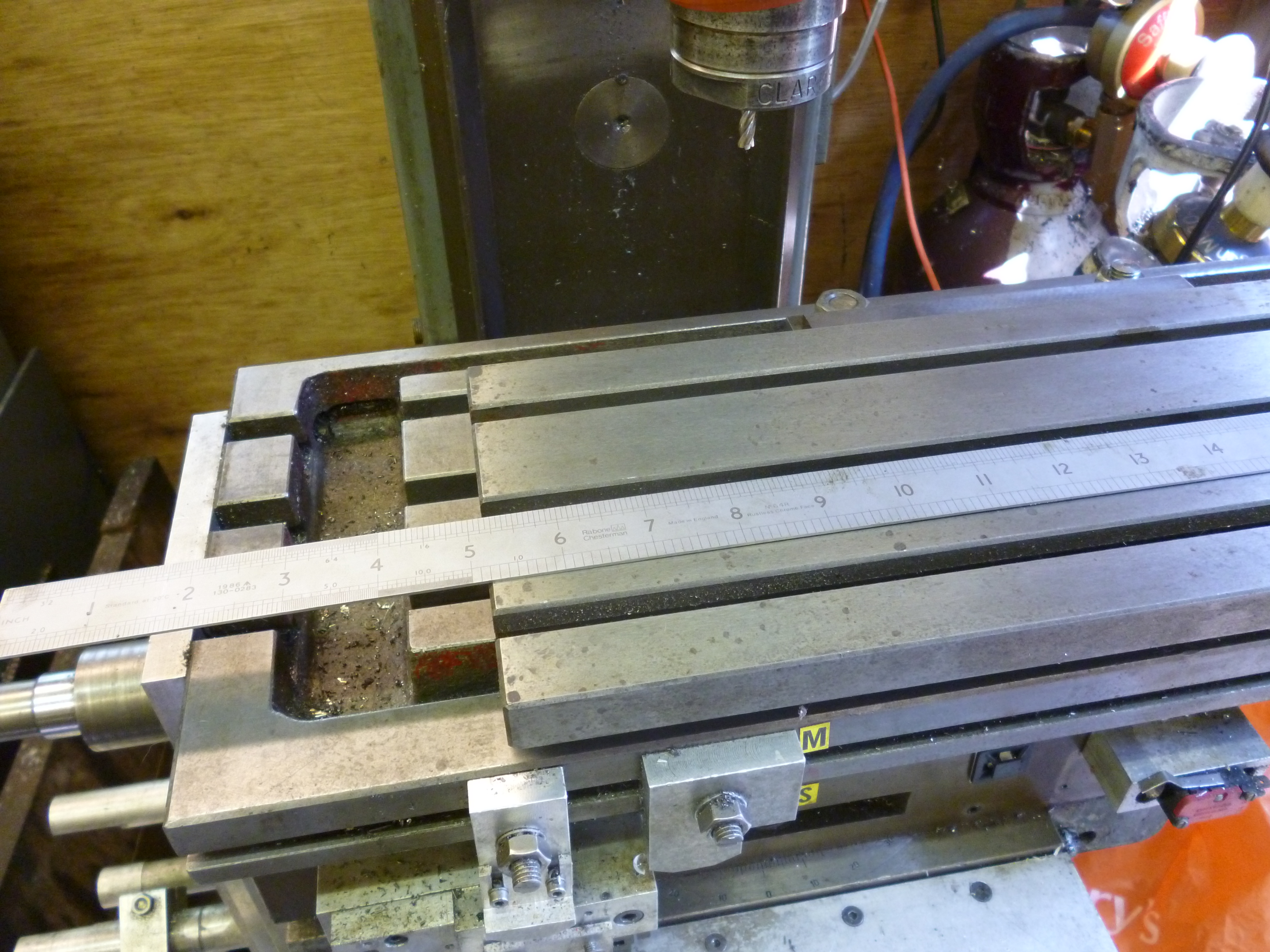
Two short fences are set up on the milling table. They both must be in line with each other and both must be parallel to the milling table. The workpiece is clamped to the sub-table. If the workpiece is rigid enough it can hang over the ends of the sub-table. In the example a 2ft ruler represent the workpiece. The sub-table is clamped to the main milling table and against the fence in one position so that one end of the workpiece can be machined by the cutter.
In this case the edge of the sub-table is higher than the fences. This is resolved by putting a parallel in between the sub-table and the fences. But if the sub-table is pushed it makes the fences tilt. The fences have to be pushed down against the milling table whilst the sub-table is being clamped. (The clamps are left out of the following photos.) The two foot ruler represents the workpiece. In all cases the workpiece is clamped to the sub-table throughout the job. In all cases the sub-table is clamped so it is parallel to the fences.

597 milling using fences 1
Fig. Machining the right hand end of the workpiece 597
The workpiece can be moved to the right in the usual way and machined as required.
598 milling using fences 2
Fig. machining the middle of the workpiece 598
The sub-table can now be slid to the right and the middle part of the workpiece can be machined.

596 milling using fences 3
Fig. Machining the left hand of the workpiece 596
Then the sub-table is slid along the fence into the last position and clamped again to the main milling table. The workpiece is machined again.
A similar technique was shown earlier using fences but not using a sub-table. But that would only work if the workpiece had a long straight edge on it (and in the right direction). This will work with a workpiece without a straight edge or, if it has a straight edge, with this edge at an angle to the x axis.
See MEW 100 p26
Swivelling sub-table
Swivelling sub-tables also exist. It is clamped to the milling machine table and the workpiece is clamped to it. It is clamped using a bearing so that the table swivels around this bearing. For whatever angle is needed the table is clamped at the far end using either an inbuilt clamp or just a standard milling clamp.
The fig. shows one made using the long milling table available from Arc Euro Trade.

466 swivelling sub-table 1
Fig. Swivelling sub-table 466
It could be used for machining tapered flutes. In such a case the workpiece has to be mounted so that the imaginary point where the lines of the two edges of the flute meet has to coincide with the axis of rotation of the swivelling sub-table. This means that the length of the swivelling sub-table needed might be significantly longer than the length of the flute to be machined.
The length is from the wide end of the flute to the point where the sides of the flute would meet when extended far enough. This is the point where the bearing about which the table swivels has to be.
In many cases it does not matter if the bearing arrangement stands higher than the surface of the swivelling table.
Making a swivelling sub-table
This is an example of where the hole for the bearings cannot be bored easily on a lathe or on a rotary table on a milling machine because of the length of the workpiece. But it can be bored using a boring head on a milling machine.
