Workholding using angle plates
Introduction
An angle plate is simply a piece of cast iron or steel that has two flat surfaces at right angles to each other. The two ends of the angle plate are also flat and at right angles to both of the two other surfaces. On some angle plates there can be webbing between the two surfaces to add to the rigidity of the surfaces. In this case inside surfaces are often just the rough surface of the original casting.
Most angle plates have on the two main surfaces slots so either face can have a workpiece, other device or the milling table attached to it. Notice the direction of the slots on one face will usually at right angles to the slots on the other face. This means that whatever is mounted on the angle plate can be move in up to two directions as needed.

20 webbed angle plate
Fig. Webbed angle plate 20
Some angle plates are made thicker so they are rigid enough without any stiffening and do not need webs at the ends. This means the internal surfaces can be machined accurately and flat. It will be seen that this is a very useful facility especially where space is limited.

21 angle plate with flat internal surfaces
Fig. An angle plate with flat internal surfaces 21
If the angle plate does not have holes in it where they are needed then they can often be drilled in it. This is not a good idea to do this too often. But it is worth doing it to achieve a common set-up like fitting a rotary table to the angle plate. In this case it can be convenient to drill and tap these holes so that studs can be fitted into them. This is can be easier than trying to clamp the rotary table using loose bolts and nuts.
Use of an angle plate
The main purpose of the angle plate is that it effectively rotates one surface, for example, a milling table, into another surface at right angles to the first.
If a workpiece is clamped to an angle plate, it effectively rotates it through 90º. When a flattish workpiece is clamped to the milling table it is usually with the large surface horizontal. In this position it is not always easy to machine the sides of the workpiece as might be required. But if we use an angle plate to turn it through 90º we can easily machine the sides.
Fig. holding a workpiece on an angle plate to machine its sides
Similarly it is possible to hold a long thin workpiece on end on an angle plate. It is then possible to machine the end of the workpiece.

543 angle plate
Fig machining the end of a long thin workpiece 543
Increasing the effective size of an angle plate
An angle plate can be made larger by bolting a flat plate or rectangular tube onto the front of it. If some rectangular tube is used allowance has to be made for the tube bending slightly under pressure. One solution to this is to fit the nut onto the bolt inside the tube on the side where something is being clamped to the tube.

404 extending angle plate
Fig. Rotary table mounted on angle plate using rectangular tube 404
Use of angle plate on end
Though it would be usual to use the two large surfaces on an angle plate the ends of the two sides are always flat and at right angles to the two sides. This end surface could be mounted on the milling table. It would have to be clamped to the table. The possible advantage of this is that very often the length of an angle plate is longer than the height of either of its sides.
Examples of the use of an angle plate on end
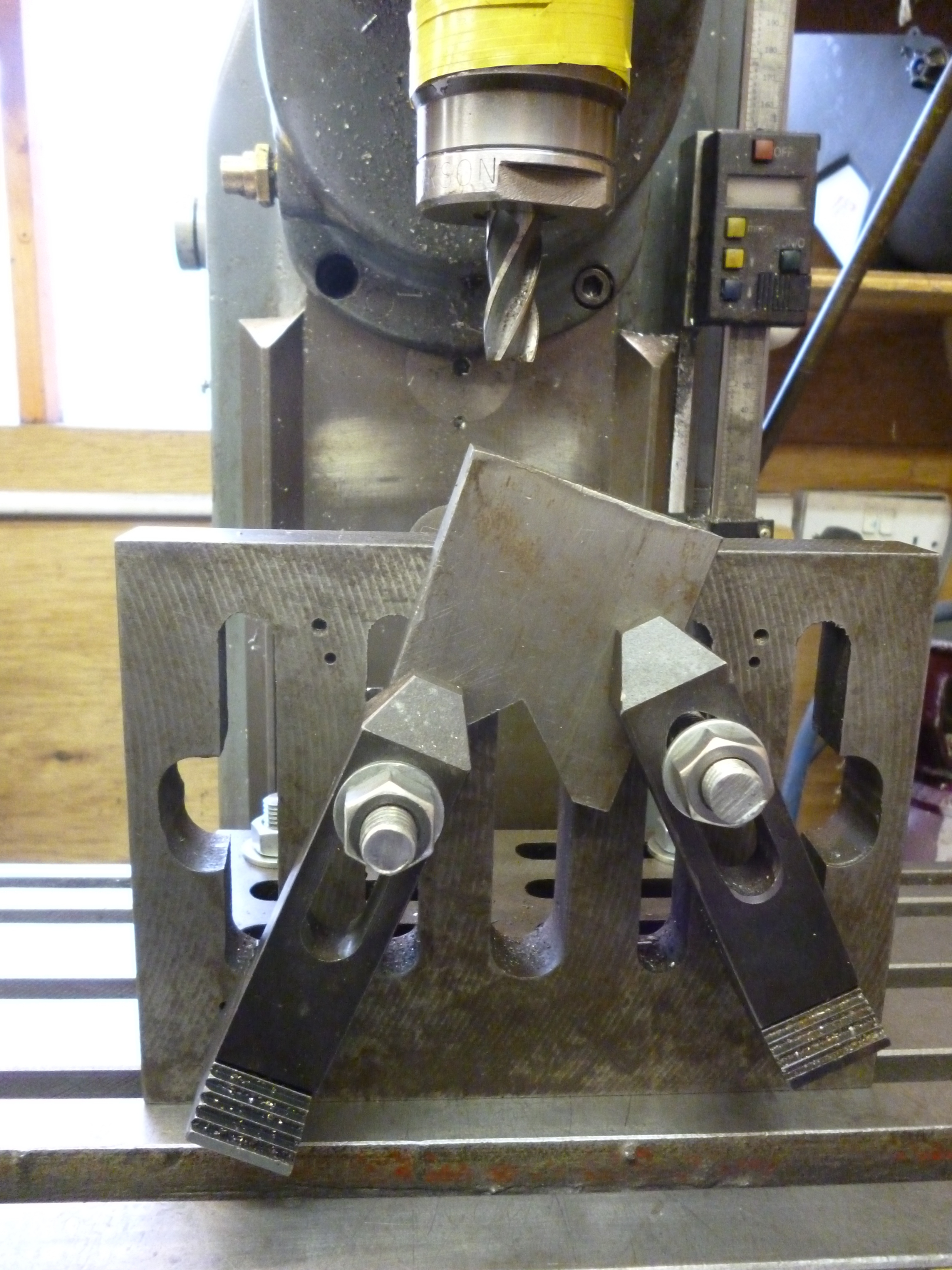
Matching two V-blocks
It might seem that two V-blocks of apparently the same size from the same manufacturer would form a pair even if not matched. In practice they can differ so much as not to be usable as a pair.
If they are going to be machined to make them match then it is easiest to match the two V surfaces and then machine the others to match. One way of doing this is to mount the V-blocks on the angle of an angle plate and then clamp them together. This might necessitate drilling holes in the webs so they can be bolted together. Then the other surfaces on the V-blocks can easily be machined to match each other.
fig – machining two V-blocks mounted together
Use of an angle plate for aligning
An angle plate can be seen as being equivalent to a square but of much greater thickness. Because of this it can be used to align two edges at right angles but where one is at a different height to the other.
This can be used for aligning vices

298 protractor, angle plate and square
Fig aligning a vice using a parallel, angle plate and square
Use of an angle plate as a stop
An angle plate bolted to the milling table to one side of a vice can be used as a stop when holding a workpiece in the vice.
Fig an angle plate as a stop
There is more on this under “Vices”
Angle plate used to mill accurate angles
One advantage of mounting a workpiece on an angle plate compared to using a tilting vice is that it can be used to mill one surface at an angle to another.
The workpiece can be mounted using clamps on the angle plate using a precision protractor. All of this can be done while the surface being used is horizontal.
543 angle plate 10
Fig. Machining an edge at an angle 543
Any method that could be used to align a workpiece clamped on the milling table, such a fences, could be used here.
Angle plates for milling edges of sheets
A setup as shown above could also be used for milling the edge of a flattish component.
Using an angle plate
Machining flutes on connecting and coupling rods
On many engines the connecting rods and coupling rods are fluted. It might seem that they could be clamped to the milling table and then milled out with an endmill.
This is not the best way to do this. Firstly the bottom of the flute has rounded corners. This can be done by grinding the required radius on the slot drill that is going to be used to mill the flutes. The ends of the flutes are not round such that the axis of the round corner is in the plane of the rod. It is “swept out”, i.e., the axis of the round part is in the plane of the rod.
This means that most of the flute can be machined with the rod flat on the milling table. But the end of the flute has to be machined with the rod held vertically. The machining can be done with a fly cutter or a T-slot cutter modified for this job.
The connecting rod has to be held near the top of an angle plate since the length of the tool is limited. The workpiece is clamped to the angle plate.

453 connecting rod
Fig. Machining a connecting rod with a Woodruff cutter 453
If a connecting rod is fluted at all then it is fluted on both sides.
Use of an angle plate with cylindrical squares
If the angle plate has two cylindrical squares mounted on it this can provide a horizontal surface at right angles to a vertical one. This is really useful for clamping flat thin workpieces in the vertical position with the bottom of the workpiece parallel to the table. Many parts are of this sort, one example is a parallel.
The squares can be set to the same height using a height gauge. The workpiece rests on the cylindrical squares and is clamped to the angle plate. It would also be possible to make two or even more parts at the same time like this. This is a situation where only one clamp might seem to be enough for light machining. It would be with a thick workpiece but it would not be enough to stop a thin workpiece vibrating. The top of the workpieces is machined with whatever will give the best finish. The part is removed and any burr removed from it. It is returned the other way up and milled to the width required.
This would be more accurate than trying to make parallels in a vice because the parallels being made are resting on two, accurate points that could be wide apart compared to resting on a narrow, hopefully flat surface at the bottom of the vice.
Fig making a parallel
Angle plate compared to use of cylindrical squares
The great advantage that the angle plate has over the cylindrical squares is that it is possible to mount a workpiece on it whilst it is in a convenient position, that is, the surface is horizontal when the angle plate is held in a bench vice. The plate can then be mounted so this face is now vertical with the workpiece still on it.
Use of angle plates – head horizontal – vertical mode
Extending the area for vertical milling – 2
But if the angle plate is the other way round, the distance in the y direction is much smaller but the space from the cutter downwards is greater.

448 vert milling horiz mode 2
Fig. Extending the milling area 2 448
This configuration allows, in principle, for the user to use a horizontal milling machine as a vertical milling machine. But it is easy to see that it is very difficult for the user to see what is going on. It is also difficult to set up the workpiece, not only because it is inaccessible but because the surface is vertical. The only way to do this is to take the angle plate off the machine, fit it in a vice and mounted the workpiece with the surface horizontal.
This setup not only increases in the new “y” direction but since the angle could be turned round the depth in the “z” direction is also increased. But this does require an angle plate with flat internal surfaces.

Fig. Increasing the depth in the “z” direction 447
Extending the area for vertical milling – 3
Suppose it is necessary to mill a piece of metal in a position further from the edge of the metal than the distance from the cutter to the column? One-way is to mount the workpiece on an angle plate at one end of the table and to rotate the head so that is horizontal. If this is done it is important to check that the gears in the head will be adequately lubricated for the work being done.
Fig. Extending the milling area 3 431
Angle plate used to enable horizontal milling on a vertical milling machine
If a vertical milling machine is fitted with a stub arbor and the table is fitted with a large angle plate with the working surface in either the x/z or y/z plane then this set-up is equivalent to a horizontal milling machine.
This is useful if the machine does not have the ability to be used as a horizontal machine. Even if it does it can be useful because it is sometimes easier to do this than remove the vertical head, set the machine for horizontal milling, do the milling and then replace the vertical head.
Fig. Horizontal milling on a vertical mill 340
Example
It is a very common requirement is to mill very narrow slots in a piece of angle steel to make a buffer beam. These side frames slot into these slots.
Fig slots in buffer beam
The workpiece could be held in a vice and cut using a small endmill. If the endmill is very small and if the job is done too quickly it easily breaks.
It would be much better to do this with a slitting saw on a horizontal machine. This can be done as described above. A stub arbor is fitted to the vertical drive socket. A slitting saw is fitted to the stub arbor. An angle plate is clamped to the table. The workpiece is clamped to the angle plate. It is only practical to set up the workpiece with the angle plate held in the (bench) vice.
Fig. 323 Milling slots in a buffer beam 405
All of the arrangements for doing this with a vice mounted on the angle plate or vices that tilt left/right are covered later.
Use of angle plates – vertical mode
Machining the end of very long workpieces
Where the machine has a vertical head fitted to the column the space behind the tool is fixed and not very large. If however the head rotates on the turret then if it is turned to one side the space suddenly becomes much bigger.
Furthermore if the head is rotated further it becomes possible to machine the end of a workpiece that is too big to be machined in the normal space between the table and the tool. The workpiece is not on the milling table but behind it. But there are not slot on the back of the milling table. This can be solved by placing an angle plate next to the edge and clamping it to the milling table. The workpiece is then clamped to this angle plate.
Fig. – machining the end of a very long workpiece – SMEE
Use of angle plates – horizontal mode
Vertical milling on a horizontal machine
An angle plate can be used to turn a horizontal milling machine into a vertical one. If the vertical type cutter is in the horizontal spindle then it is necessary to rotate the milling table through 90 to get there.
Fig. Vertical milling on a horizontal machine 449
