go to the page above his one – “Workholding – links”
Tilting Devices
When it is necessary to tilt a workpiece (workholding device are covered later) there are several choices. Most of them are only suitable for a certain range of angles.
Tilting tables are often graduated but these graduations can vary considerably in their accuracy. (This is also true of other devices such as vices, which are covered later.)
Tilting devices that depend upon the sine bar principle can be setup, accurately, because they use this principle.
If a device tilts, say, up to 30° from the horizontal then if a workpiece is placed on it one way round it will tilt down 30° below the horizontal. Similarly, if the device is fitted the other way round then it will tilt up 30° above the horizontal.
It might seem that if it was necessary to tilt a dividing head then simply putting something underneath it at one end would achieve the required result. But, firstly, it is usually necessary to set the device at an accurate angle. Secondly it is always necessary to fixed it to the milling table securely. This means to pieces of metal are needed at either end. They both need to have their top surface at the right angle at the point where they are clamped. Even then they will only work properly if they are a certain distance apart.
If the two ends of whatever was being tilted were a long distance apart this would be a possible solution.
The wedge
The simple way of tilting a device (or workpiece) is by means of a wedge.
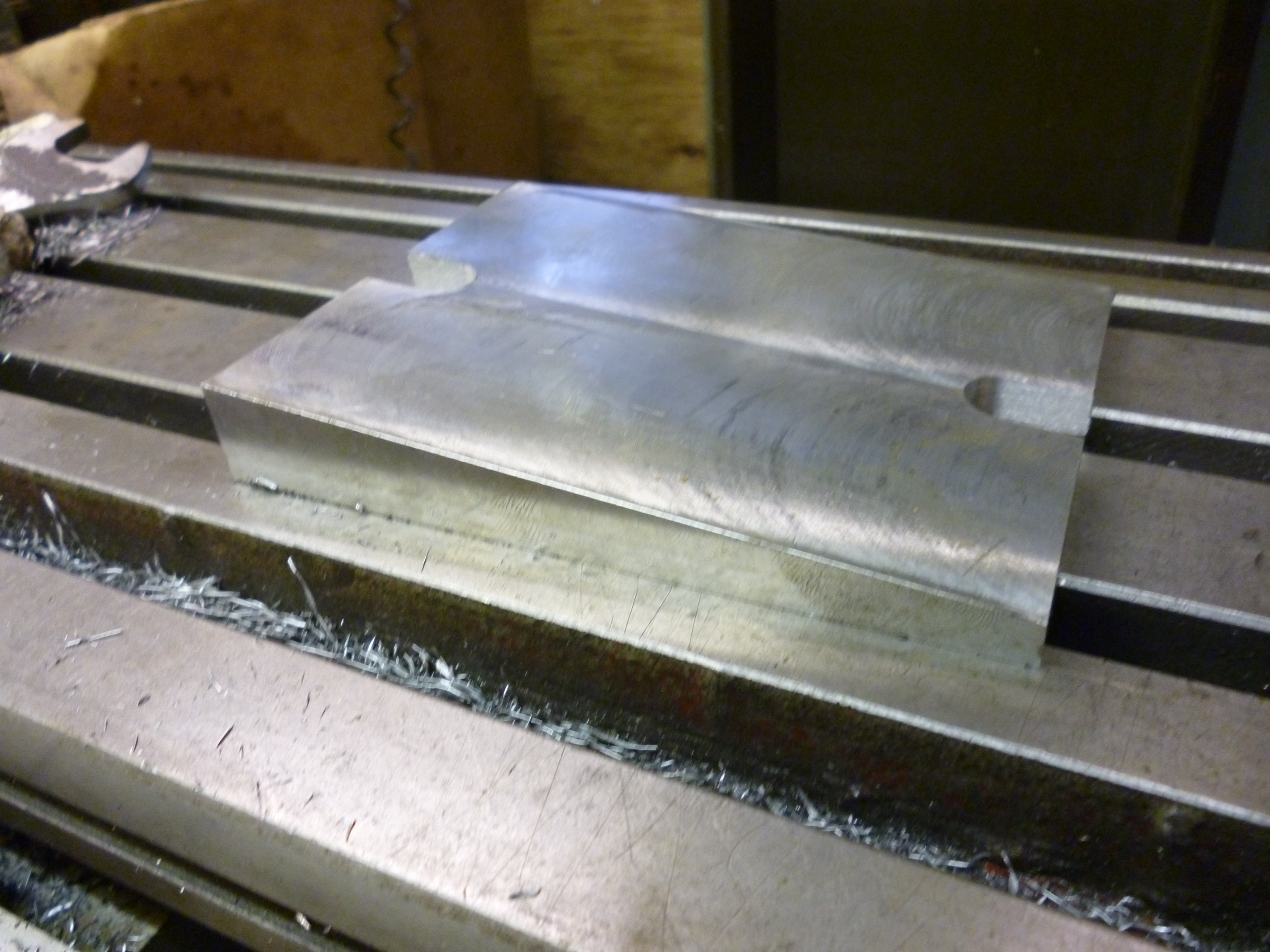
427x a wedge
Fig. A Wedge 427
For the wedge to be able to hold another device properly it is necessary to use bolts with tapered washers. The tapers on the washers matching the taper on the wedge.

4602 bolt with tapered washer
The most obvious limitation of the wedge is that the angle is fixed. The one shown above was made by holding the workpiece, i.e., the wedge to be, using a rack vice as described later. This wedge was made to tilt a particular device – a dividing head at an angle of 5°.
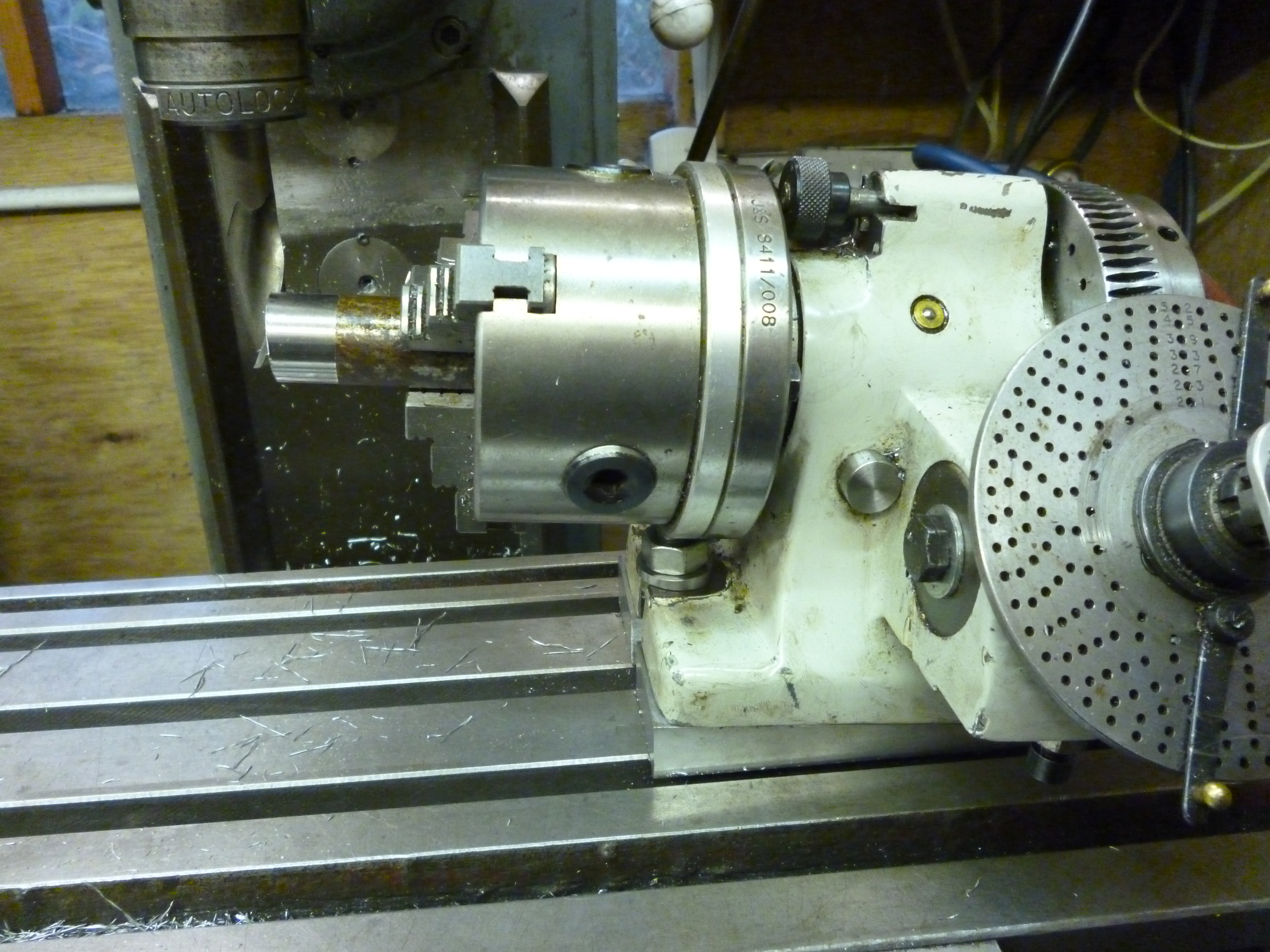
6100 dividing head on wedge
One of its great advantages is its very low height. It is only suitable for small angles.
A wedge of 5° will tilt a dividing head – one way round. But it will also tilt it by -5° if it is turned round the other way.
Two wedges of different angles can be used together to make other angles. For example a 5° degree and a 3° wedge will not only make 5° + 3° i.e. 8° but also 5° – 3° i.e. 2°. And, of course, all of these can be turned round to give –5°, -3°, -8°, and –2°.
Tilting Table
The tilting table is exactly what it says – a table that tilts. The type that is readily available will tilt is from 90º one-way though being horizontal, 0º, to 90º the other way.
40x tilting table 1
Fig. Tilting table 40
Its main disadvantage is that in order to do this the height of the table above the table of the milling machine is roughly equal to the width of the table. This often precludes the ability to mount other gadgets on the tilting table without them hitting the cutting tool.
Sometimes the slots for mounting the tilting table are only at either end of it. This means the tilting table can only be mounted on the milling table along the x-axis. To mount it along the y-axis can be done by mounting it on a sub-table (or metal plate) that can then be bolted to the milling table.

551x tilting table on subtable
Fig. tilting table on a sub-table 551
Tilting angle plate
Some angle plates have two surfaces that are connected by a joint so one surface can tilt relative to the other.
This is one of the few ways of easily getting a surface that can go from being horizontal to vertical.
However it is not as rigid at the tilting table. Also it would be very convenient to be about to mount rotary tables etc on it but the tilting angle plates that are available are often very small.
fig Tilting table/tilting angle plate – setting the angle
see PP26 on setting one surface at an angle to another
Sine plate
The sine plate is a variation on the traditional sine bar. The plate has two round bars attached to it at either end just like a sine bar. The traditional sine bar is often used in situation where it does not need to be clamped, for example, on a surface plate for marking out. But if it is to be used to hold a workpiece that is to be milled then the sine plate has to be clamped. If it is tilted this is not always easy.
There are several ways of getting round this problem. The round bars can be extended out from the sides of the plate. This can take up too much space on the table. Alternatively the round pieces can be exposed as shown in Fig.
Fig sine plate
Normally, with the sine bar, one end would be raised using slip gauges. In this case since considerable force is used to clamp the plate two piles of slip gauges would be needed. A simple solution to this is use one pile of slip gauges to set the height and then have some other means to clamp the sine table in this position.
Holes are drilled in the plate in order to be able to clamp the workpiece (or other workholding device to it).
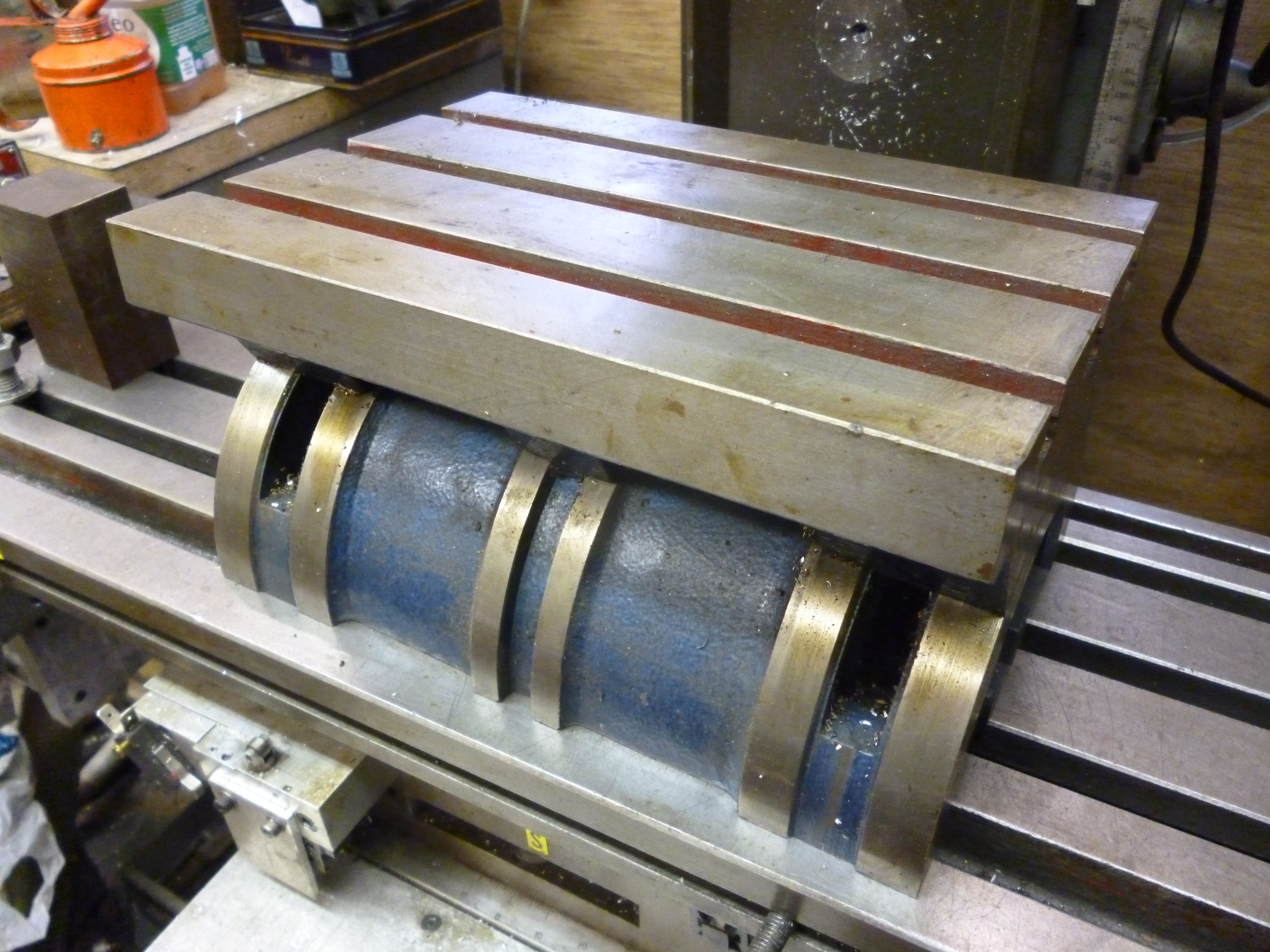
Sine table
A sine table is similar to the sine bar except it is much wider and might have T-slots on it. The angle is determined by the height the table is raised at one end by using slip gauges. The advantage of the sine table over the tilting table is that its height is far lower than for a similar angle on the tilting table. But on the other hand it can only be used up to about 30º.

38x sine table
Fig. Sine table 38
Compound sine table
It is possible to get sine tables that tilt not just on one axis but on two, which are at right angles to each other.
If the table can only be fitted one way round on the milling table then this has the advantage that the workpiece can be elevated along either the x or y direction.
If the table is tilted in both the x and y directions at the same time then the resulting angles are compound angles.
As with sine bars etc, most sine tables are designed for measuring and other light work. Such a sine table can be modified to be suitable for milling. In particular it needs to be possible to clamp the workpiece to the compound sine table, it needs to be possible the clamp the compound sine table to the milling table. It also needs to be possible to clamp the movement so it cannot move either up or down during any machining.
The real problem with a compound sine table is its height. It will only be useable on larger milling machines.
