Go to home page
Go to page above
Features of the milling machine
Vertical and horizontal milling machines
There are horizontal milling machines, there are vertical ones and there are horizontal ones that can be used as vertical ones.
As has already been pointed out, if there is a choice between a vertical and a horizontal the vertical has to be the choice. After all, if necessary, most of the things that can be best done on a horizontal machine can, at a push, be done on a vertical machine as other pages on this site make clear. But it is not practical to try to use a horizontal machine to do those jobs that are easily done on a vertical machine.
Horizontal machines
Since horizontal machines have a horizontal arbor at a fixed height they have to have a knee that moves up and down.
In general, these machines have rectangular columns. When used as horizontal machines the arbor is supported by a bar that comes out from inside the column or there is an arm that fits on top of the machine by means of a dovetail. for many types of job this arrangement where the arbor holding the cutter is supported at the far end increases the rigidity of the system so that the rate of removing metal is higher that it would be otherwise. This is of great importance in industry.
For the amateur, horizontal machines are of interest because they often have, as an optional extra, a vertical head. One limitation of this approach is that the distance between the cutter and the column is limited. On the other hand the column/vertical head structure is very rigid.
There are at least three ways of doing this.
1 The spindle for the horizontal arbor drives this vertical head. This can be done with just a pair of bevel gears. This can mean the space between the vertical cutter and the tale is restricted.
Examples are:
Tom Senior,
fig
Elliott Omnimill with the universal head,
Fig
2 The horizontal spindle drives some spur gears that raise the height of the of the horizontal drive. This is then uses two bevel gears to provide a vertical spindle.
Examples:
Harrison
Fig
Another way of doing this occurs on the Aciera 23 milling machine. The machine has a socket for the horizontal arbor at the top front of the column. When this is used there is a support arm fitted in a dovetail on the top of the column.
When vertical milling the vertical head is fitted on the end of a similar arm. The drive to the head goes through this arm and engages a gear on the shaft of the horizontal drive.
Fig.Aceria 23
Roger Trewinnard
Refurbishing an Aceria 23 Milling machine
MEW 171 p40
3 The horizontal spindle is not used but the motor is used. The power is taken from the motor to the vertical head. The vertical head is mounted on the top of the column so its height is more useful.
Example
Fig. Centec?
Fig
4 The vertical head is a completely separate item and has its own motor to drive it. Consequently the height of the vertical head is fixed but, of course, the table moves up and down. In this case the structure is not so rigid as in the previous cases.
Example:
Elliot Omnimill
Fig
In all of these cases the vertical head might or might not have a quill feed.
A quill feed is the most convenient way of changing the distance between the workpiece and the cutter. But the range possible with a quill feed is limited if rigidity is not to be compromised. This means that either a table that moves up and down or a vertical head that moves up and down is needed (or both in some odd cases).
Purely vertical machines
Then there are milling machines that are made simply to be just vertical milling machines.
These can be divided according to two distinctive features. Firstly, the machine has a knee that moves up or down. Secondly the milling head is on an arm that moves in and out.
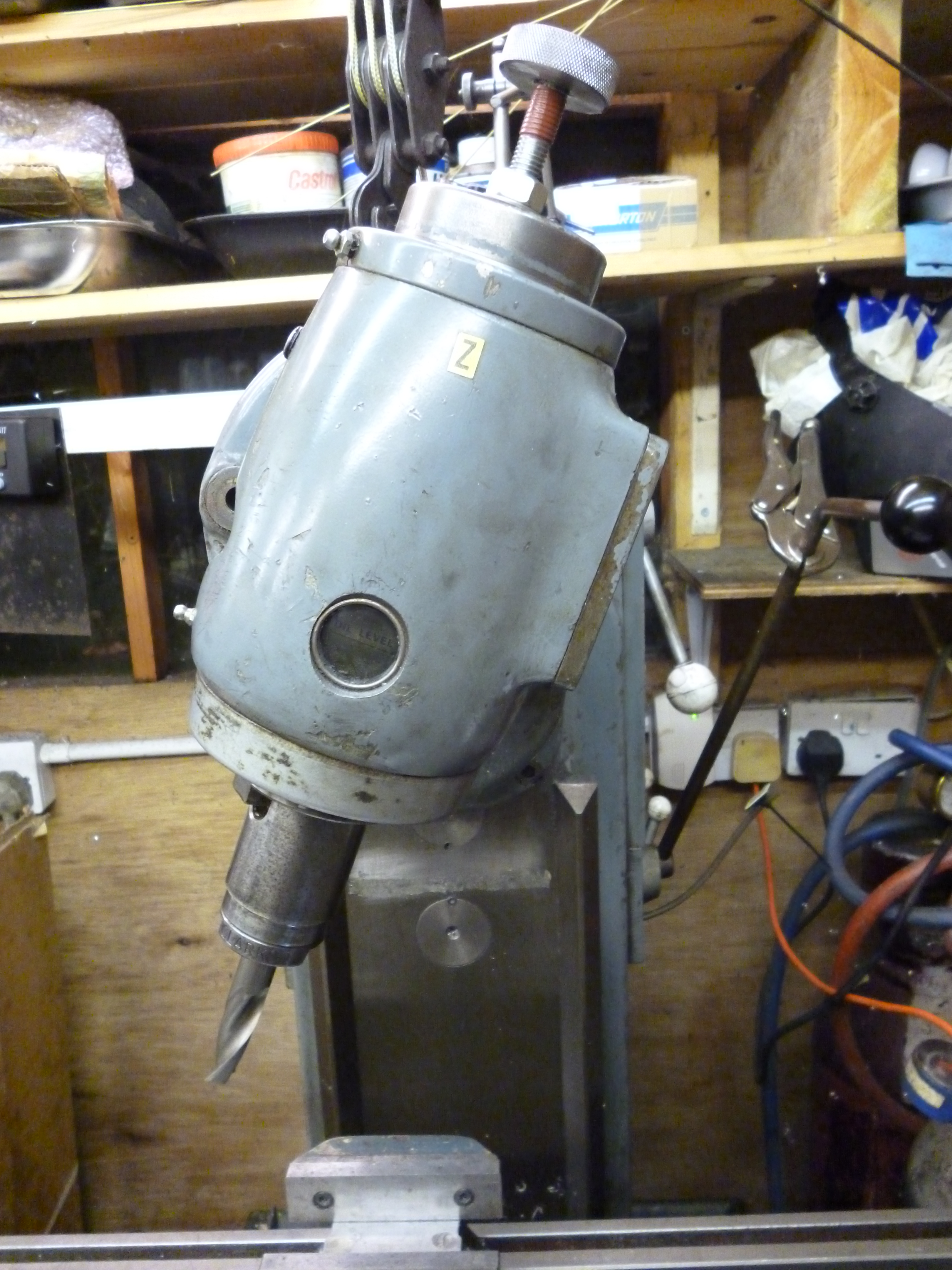
The simplest arrangement is where the milling table is mounted on the base of the machine. Then there is a fixed column. Then the head is fixed to the top of the column. The only mechanism for changing the distance from the cutter to the milling table is a quill feed. The whole machine is very like a bench drill fitted with an x/ table.
fig Clarke micromill
Machines like this can be very small and can be used on an ordinary table top. They can be large enough that they are floor mounted.
fig large milling machine without a knee
The most common large purely vertical machine is probably the Bridgeport.
In other cases this head, though fixed, has a quill arrangement that allows the tool to move up and down. An example of this is the Bridgeport.
Fig.Bridgeport milling machine
Some horizontal machines have the option of having a vertical head that fits on top of the column. It does not use the horizontal spindle to drive it but has its own motor and belts to change speed. An example of this is the Elliot Omnimill.
Using a Bridgeport Mill, Ian Howitt, MEW 171 p18
Knees and Quill feeds
All milling machines have a table that goes from left to right and in and out. But there are three ways of getting the up/down movement.
Firstly the table can move up and down. This is done with a “knee”. The knee moves up and done with the milling table on it. The benefit of this is that the movement can be very large. It is not that this is necessary during a milling operation but it allows for a large difference in the height of the workpieces that can be machined. On the other hand it is often only possible on a floor mounted, and hence, large machine.
This is usually done using a system of dovetails or similar so the table moves very accurately.

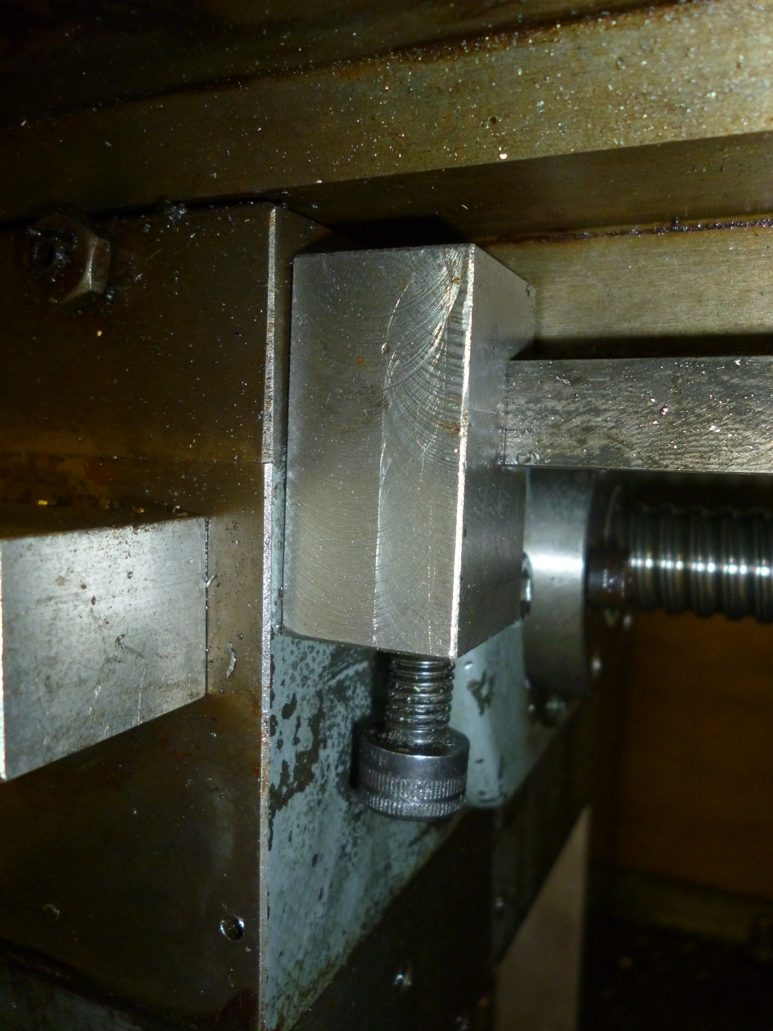
655 dovetail on vertical column
Fig dovetail on the column of a Bridgeport 655
It is, therefore, possible to machine the workpiece whilst moving the table up and/or down.
Secondly it is possible for the head to move up and down. This is very common of smaller machines, for example, bench mounted milling machines. It is possible for the head to move up and down using a system of dovetails or equivalent. However one of the main reasons for making a small milling machine is to reduce costs. It is cheaper to make a head that moves up and down by making the machine have a round column and the head fits this. If this is the case it is quite difficult to ensure that the head does not rotate very slightly when moving up or down. So it is not always practical to machine whilst moving the whole head up and down.
The third way is to have quill within the head so the head can stay still whilst just the quill and the cutting tool move up or down.
This gives us the following permutations – simplest and hence, cheapest, first.
The simplest arrangement is for a fixed (height that is) table, fixed head and a quill to provide the only up/down movement.
Next is a head that moves up and down but this does not allow for milling whilst moving the head so it is necessary for this head to have a quill for going up and down whilst machining.
The next is a fixed head with no quill but the table goes up and down. The snag with this is that it is much harder work to move the table up (but not down) than to move a quill up and down. But it does give a large range of movement even if machining.
The Harrison milling machine is this sort. (There is a rumour that there is a vertical head for this that has a quill feed but no one has ever seen one.)
If the table goes up and down it is unnecessary for the head to go up and down. Having a fixed head increases the rigidity of the machine. But it is easier to use if the head has a quill feed. This is the best but the most expensive arrangement.
The Elliott Omnimill and the Bridgeport machine are machines of this sort.
Round columns
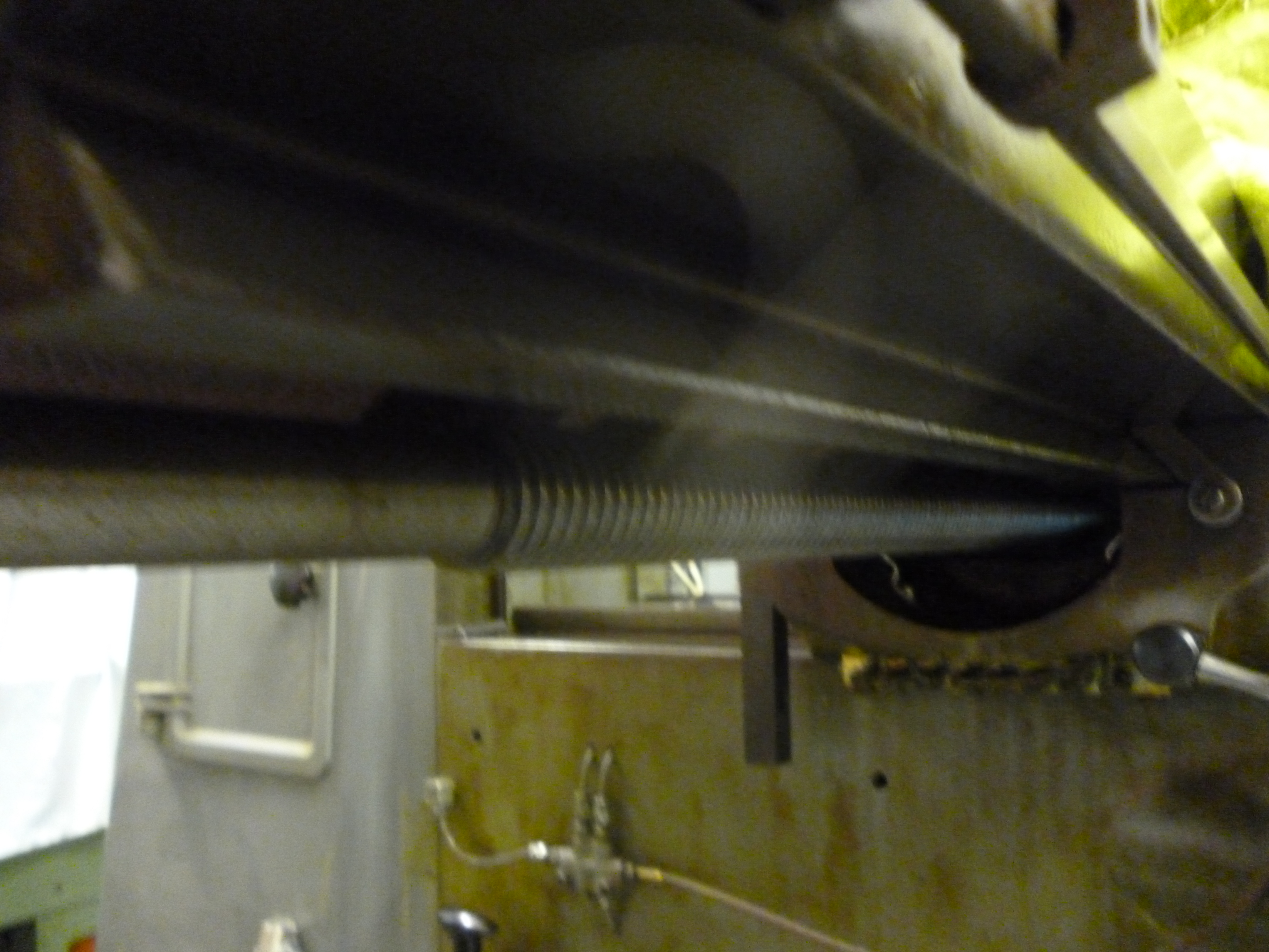
On larger machines the column is often a large casting of a roughly rectangular shape. The knee fits it using a large dovetail. The knee is always driven up by a large leadscrew under the knee. This means that though the knee can be very heavy it is balanced on this leadscrew.
This sort of system is rigid enough that it is possible to machine accurately even as the knee moves up or down.
On smaller machines the column is often just a round part. The whole of the head can move up and down this column.
The advantage of this is that it is cheap to make. The problem with it is that it is very difficult to make such an arrangement rigid enough that the workpiece can be machined as the head moves up or down. In practice milling is done with the head in a fixed position and any up/down movement is done using a quill.
See mew 144 p34
The milling table
The workpiece is either mounted directly on the milling table or on some sort of workholding device or devices that is/are mounted on the milling table.
On all milling machines this table can be move left/right and in/out.
This, again, is often done using dovetail joints.

656 dovetail on knee
Fig dovetail on the knee of the Bridgport 656
This is for the in/out movement of the milling table.
657 dovetail underneath table
Fig dovetail for the left/right movement on the Bridgeport 657
Right angle drives
It is possible to get attachments to fit a vertical milling machine to turn the drive through 90º. It can then be used to hold a stub arbor. This then allows a cutter to be used in the same position as it would have been on a horizontal machine. That is, the cutter lies along the x-axis. If, alternatively, the cutter can lie along the y-axis then other possibilities arise
.
Gears and belts
It is usual for the spindle to be able to run at a variety of speeds. Different types of cutters, but more importantly, different sizes of cutters are best used at different speeds. In general the larger cutters are run at low speeds while small cutters are best run at higher speeds.
The spindle speed may be selected by using a gearbox or by changing pulleys on belt driven machines or by a combination of both. Gears are easier to change but using belts and pulleys is cheaper to manufacture.
Gearboxes
Most gearboxes are designed to run with oil in them to lubricate the gears. This is essential to minimise the wear on the gears. The gears are not completely immersed in oil but the bottoms of the gears are. The rotation of the gears is more than sufficient to splash the oil everywhere.
Most gearboxes have a sight glass that might show the level of the oil in the gearbox. Often, especially on old machines this can get dirty on the inside and can be totally misleading. It is sometimes possible to remove the top of the gearbox to see the oil level. Alternatively it is possible to make a dipstick out of the wire of a metal coat hanger to test the amount of oil in the gearbox/gearboxes. But it is not always easy to see what the level of the oil is with this.
Any gearbox that is designed to hold oil will have a drain plug to empty the oil. It is often possible to remove this plug and fit it with a nipple. A short piece of plastic tube is fitted to this nipple. The end of this tube is held up higher than the level the oil is meant to be at by means of an adhesive clip and a cable tie.
Manufacturers seem to recommend very different oils for similar gearboxes. It is probably vital that there is oil in a gearbox but not so important what sort of oil it is. However if the viscosity of the oil is too great the churning of the oil will create heat. There is always a temperature at which the oil will lose its oiliness or decompose. One rule of thumb is if it is too hot to touch it’s too hot.
Clutches
On some larger machines the drive to the cutter can be controlled using a clutch. Where the motor uses a 3-phase supply this can be very useful if the supply is a bit iffy. The motor can be turned on before applying it to the cutter. This reduces the load on the supply.
Power feeds
On very small milling machines all the feeds will be operated by hand. On larger machines the x-axis feed is often powered. Very often this can operate at different speeds by means of a gearbox though the gears may need to be physically changed by hand. On very large industrial machines the movement on all three axes can be powered.
Power feed is useful where a workpiece is machined from one side right through to the other. It is quite easy to arrange for stops to automatically start and stop the feed or even reverse it in such cases. But otherwise is not worth the risk.
Sometimes the power is derived from the main motor that powers the spindle. Very often it is a separate motor that is fitted to one end of the milling table. In this case the other end will have a handwheel.
Table stops
Often it is necessary to machine a slot or a square hole that is too deep to be done in one cut. The trick here to getting a nice, clean finish is to use table stops. A table stop is a mechanical device to limit the movement of the milling table in any direction. Usually there are table stops for limiting movement in the x direction. Sometimes there are some for the y direction and, rarely, for the z direction.
It will be seen later that there is another type of stop, which is fitted to the surface on the milling table. This will be referred to as a “stop”.
The stopping action has to be decisive so the table stops have to be clamped very firmly. Table stops for the x-axis are often fitted by bolts to a T-slot along the front edge of the milling table.
Fig. T-slot for stops

86 table stop
Fig Table stop 86
678 table stop fitted
Fig Table stop fitted 678
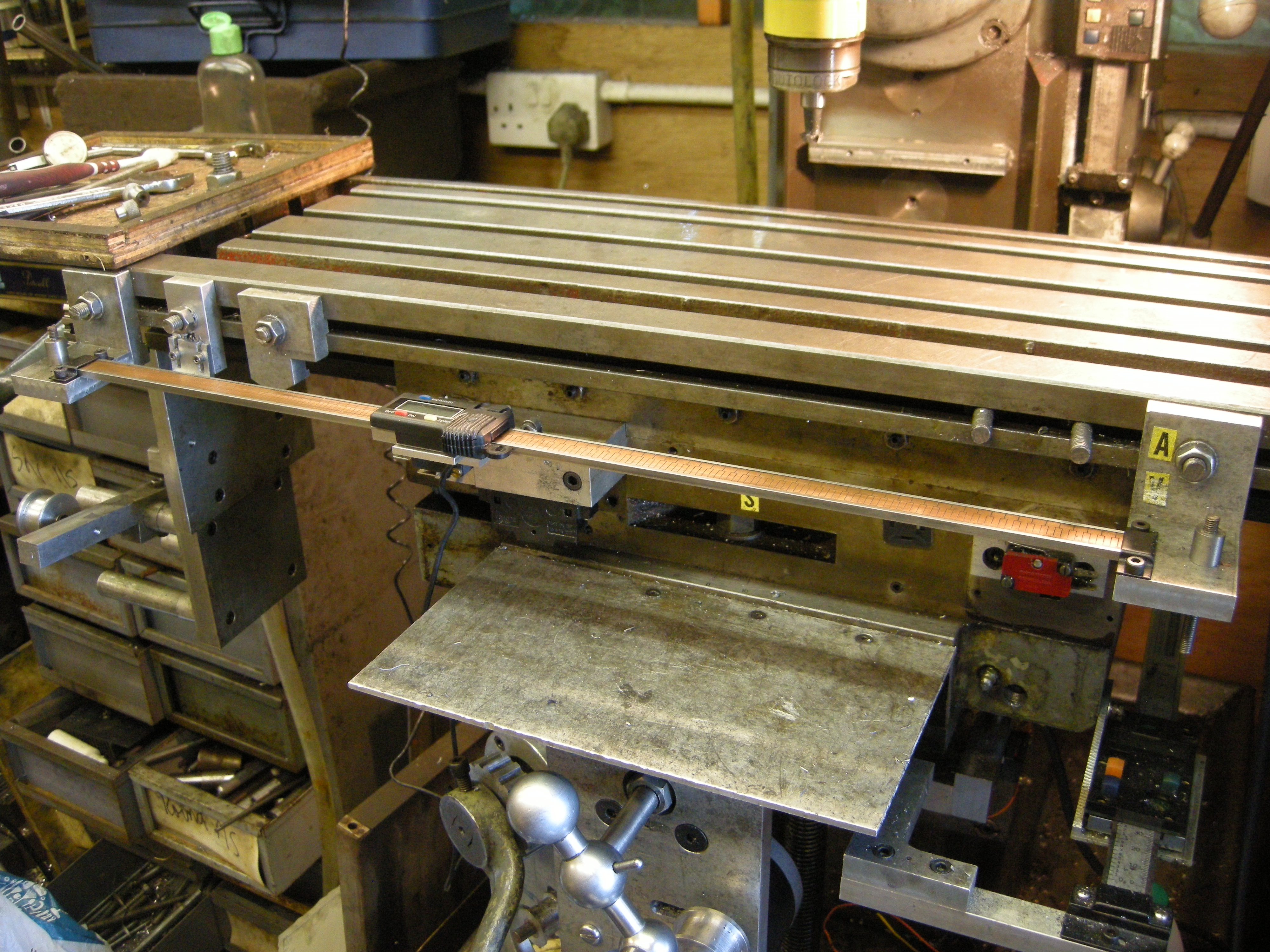
In the figure below this slot has been used for holding a DRO and switches for CNC milling. The table stops are simply little clamps that fit the guides on the milling table.
The two key features are that the material doing the clamping is soft, for example, phosphor bronze, and so does not mark the machine. Secondly it is made so the soft material part cannot fall out.
A table stop with one screw clamping it, like this, will not shift along any line going through this clamping screw. However it is quite possible that it will rotate about the axis of this clamping screw. Check that when the table stop hits the limit it cannot rotate.
If the machine has a knee then table stops can be used to limit the movement of this. Since the force needed to raise the knee is very large it is necessary for this table stop to be robust enough to be able to limit the movement of the table.
If is also possible to have table stops on the vertical movement of the cutting tool. If the machine has a quill a “stop” that limits the movement of the quill is equivalent to a table stop in the z direction. Since the quill is feed directly by hand the feel of this is much more sensitive and the (table) stop does not have to be as robust as those where the movement is geared.
Y-axis Stop attachment for Senior E mill, Shelley Curtis, MEW 44 p16
Notice it is only possible to machine between two table stops as they are usually implemented. It is not usually possible to use table stops to define one cutting edge on one side of a workpiece and then use another table stop to define the outside edge on the other side of a workpiece.
On locking a movement
It often pays to lock any movement in any of the directions not being used during any particular cutting operation. Usually, at any moment in time, movement is only occurring along one axis.
For the highest accuracy it always pays to lock every movement except the one being used.
On a larger machine with a knee it is often not necessary to lock against movement in the z direction because the weight of the knee is often sufficient to prevent the risk of any unwanted vertical movement.
Heads that tilt
On most mills that have vertical milling heads, this head can be tilted. This movement is always in the left/right direction, that is, in the x/z plane.
418 titled vertical head
Fig Head tilted in the x/z plane 418
The angle of tilt is usually marked on the milling head. This is usually good enough on those occasions when the head has to be tilted. But most of the time the head is used in the vertical position. And in most of these cases it is important that the head is aligned very accurately. This process is known as “tramming”
See
Tramming – aligning the vertical head to be vertical in the x/z plane
It will also be seen later that this feature can be very useful on larger milling machines. But on small mills it is often found that if the angle is large the cutting end of the tool is a long way to the left or right of the table and the movement the tool can cut along the x-axis is very limited.
Some vertical heads can be tilted in both the x/z and y/z planes. It should be set as accurately as possible in both directions using the scales on the head. It should then be aligned in the x/z plane followed by the alignment in the y/z plane.
When tramming the head in x/z plane it should be obvious whilst doing this if it is vertical in the y/z plane.
Vertical heads that rotate about the column
On a milling machines like the Elliott Omnimill and the Bridgeport the whole of the vertical head can be rotated around the top of the column. This allows such a head to reach spaces that other machines cannot reach. For example a workpiece can be clamped to the back of the milling table with part of it hanging down behind the table. It can then be machined.
Fig. vertical head on the Bridgeport
On the Omnimill this rotation about the column is calibrated. The head also tilts left/right. The combination of these two movements gives an angle in the y/z plane.
Milling tables that swivel
This feature is only found on horizontal milling machines. It is this feature that makes the universal mill universal. Unless the machine can be fitted with a vertical head, this feature is essential for helical milling. This is because where the cutter is in the form of a round disk rotating about its axis, like a gear cutter, the movement of the workpiece has to be at an angle, the angle of the helix, for the cutter to cut properly.

91 Milling machine with table swivelled
Fig Swivelled table 91
On a vertical milling machine a helix can be cut without a swivelling table by using a stub arbor with a horizontal type cutter in the tilted vertical head.
If a horizontal mill is not a universal one it can be assumed that the movement in the x direction is at right angles to the y direction. On a universal machine this is not the case. When the table is not being used at an angle then the user has to check that the angle between the x movement and the y movement is at right angles. In this case the accuracy is critical whereas for helical milling the angle is not so critical and can often be set using the graduations marked on the machine.
A swivelling table can swivel a bit more than 45º one-way or a bit more than 45º the other way. Altogether this gives at least 90º. This might appear to be useful. However it use is limited because the natural movement in the x and y directions are now both a 45º to the new frame of reference.
If the axis of the horizontal arbor is taken as 0º and the table swivelled through 45º then the x direction handle moves the table at 45º but the y handle moves the table at 0º. The feeds with the table straight are at 90º to each other. But if the table is swivelled the maximum angle between the two feeds to each other is only 45º.
With the table swivelled at 45° the movement in the y direction will be reduced by about 50% from what it is if the table is not swivelled.
Lubrication
There are two types of substance that are used for lubrication. The first is oil. This is useful for lubricating large surfaces that slide against each other. The second is grease. It is not suitable for sliding surfaces but is good for filling spaces in bearings where oil would run out.
One problem with lubricated surfaces is that any dust falling on the surfaces will stick to it. Not only is it necessary to oil it but it is also necessary to frequently clean it with kitchen roll and then re-oil it. It is clean when the paper comes off and is only coloured by the “wetting” of the oil.
In general any lubricant is better than no lubricant.
Slideway lubricant
Special oil is sold as “slideway” lubricant. It is designed for vertical slideways. It is extra viscous to stop it running down such a slide.
Grease nipples
Lubrication is often done by means of what are commonly called “grease” nipples. This does NOT mean that they are necessarily for grease. It has to be determined whether surfaces are to be oiled or bearings are to be greased.
Sometimes there can be so many of these without it being clear which is what that it is worth making some sketches for future reference.
Some “grease” guns can be filled with oil as is necessary to oil “grease” nipples.
One shot lubrication systems
Applying oil to a grease nipple is not easy. Furthermore there might be a lot of grease nipples. One solution to this is a one-shot lubrication system. This consists of a pump immersed in a container holding the oil. This is usually hand operated. One pull on the lever supplies enough oil to all the points that need it. Hence one shot. This feeds oil to a manifold that feeds as many pipes as are needed to the nipples that need oil. The ones that need frequent oiling are two for the guides for each of the x, y and z-axes. “Metering units” are required to ensure that the amount of oil going into each point is balanced.
The nipples that need greasing are the ones for the bearings and nuts for the leads screws and those on the spindle. If the machine uses pulleys then any stub axles with pulleys on them need oiling.
See MEW 156 p20
Moving the workpiece
When a workpiece is being machined is it invariably necessary to be able to move it relative to the cutting tool by a precise distance. There are two ways of doing this. Firstly there is the traditional way – movement is measured by the graduation on the hand wheel turning a leadscrew. This is not always easy. Often a movement is so many full turns followed by so many graduations. On top of this it is difficult to keep track of the origin of all the movements. Because of backlash the reading will only be right if the readings are taken when moving in one direction (for each axis).
The alternative is the digital readout or DRO. This can be set at an origin and can then be used to move to any position from this origin by an amount that can be read directly off the readout. Furthermore the reading is of the actual position of the table relative to the cutter regardless of any backlash in the system.
Digital Readouts – DRO’s
A simple digital readout consists of two parts. One part is the scale. The other is the part that slides along the scale and has the readout on it. There is often a display unit on this that gives a reading. This display unit moves along the scale and the reading shows the current position of the display.
Suppose the scale is fixed along the front of the table. The display is fixed to the part that the table is fixed to. It could also be the other way round. It is simply a matter of convenience.
It is possible on some cheap DRO’s to buy a separate display. The advantage of this is that the display can be somewhere that is easy to see. But, more than this, the scale can be covered up permanently. This protects it from dirt, which can easily damage it.
226 dro uncovered 2
Fig DRO uncovered 226
The maximum accuracy of cheap DRO’s is about 0.02mm or 0.001”.
Simple DRO’s and the problem of dirt
On many cheap DRO’s the display is integrated into the part that “reads” the scale. This means the scale cannot be completely hidden. The scale is exposed to all sorts of fluids and small particles of metal. These get between the printed circuit board inside the part with the display on it and the scale. This dirt can easily spoil the printed circuit board.
The first sign of this is when the numbers on the scale start to jump from one number to another completely different number.
The temporary solution to this is to take the body of the DRO apart so it comes away from the scale. It will be seen that the part that moves over the scale is actually a printed circuit board with strange shapes etched on it. Make sure this is clean and the scale is clean. Then fit the body back onto the scale and screw the two parts back together. But often the printed circuit board is damaged beyond repair
A more permanent solution to this is to have the DRO permanently fitted but to have a cover over it that is only removed when it is being used.

227 dro covered
Fig DRO with cover 227
Remote displays for simple DRO’s
It is possible to get a remote display for the simple type of DRO. Using one of these means that the scale mounted on the milling machine can be covered up permanently.
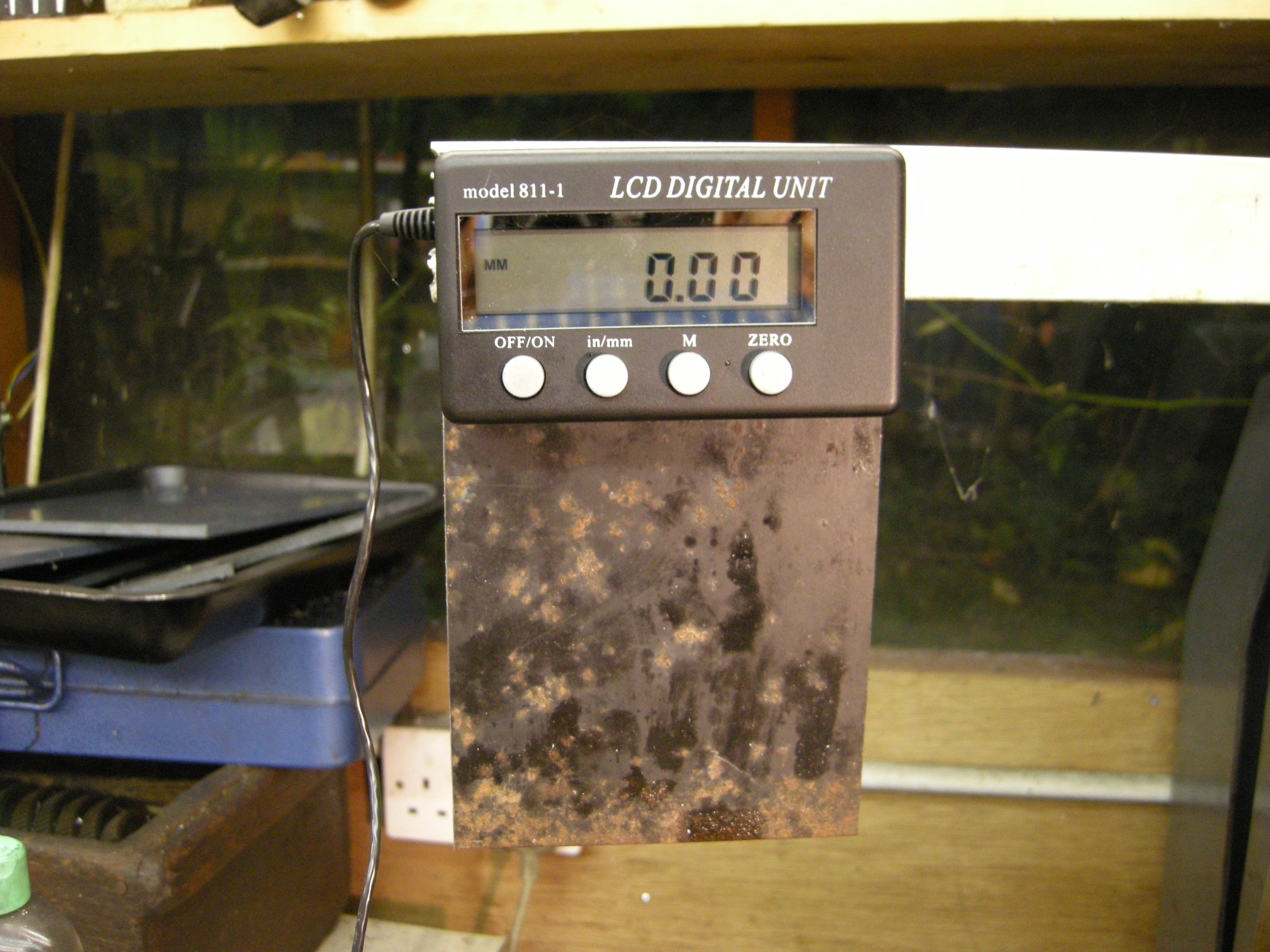
223 dro remote display 2
Fig DRO remote display 223
These only contain one display. For each axis you will need one of these.
When it is connected it is possible to set the sensor to zero remotely. It can also switch between imperial and metric and for movement to be in either direction. But it is not possible to turn the sensor part on and off remotely.
DRO’s and batteries
A second problem with the cheap sort of DRO’s is that they run on a small battery. If the battery is left in and the DRO is only used now and again it will invariably be the case that the battery will be flat when it is needed. The simple solution is to take the battery out when not in use.
It is also possible to take the battery out and solder wires to the battery terminals. These can be powered by a power supply running off the mains.
Simple DRO’s functions
The display will have a zero button so if there is a zero point on our workpiece then when the center of the spindle is over this point we set the scale to zero.
It is useful when making a drawing to draw all of the distances along each axis relative to this zero point.
This avoids all the problems of keeping track of the turns of the hand wheel.
Most digital readouts have a button so they will either work in imperial units or metric units.
It is also possible to get home made systems that use some of the cheap commercially made parts.
See http://www.groups/yahoo.com/group/ShumaTech/
MEW 111 p12
Better DRO’s
On more expensive DRO’s the scale is often made of glass and is completely hidden. It is always connected to a remote display by a long cable. The display can be placed in the most convenient position for the user. This usually means it is far away from flying swarf, dirt or the risk of being damaged. The display unit will often have a large number of useful functions built into it.
Professional DROs are always mains powered.
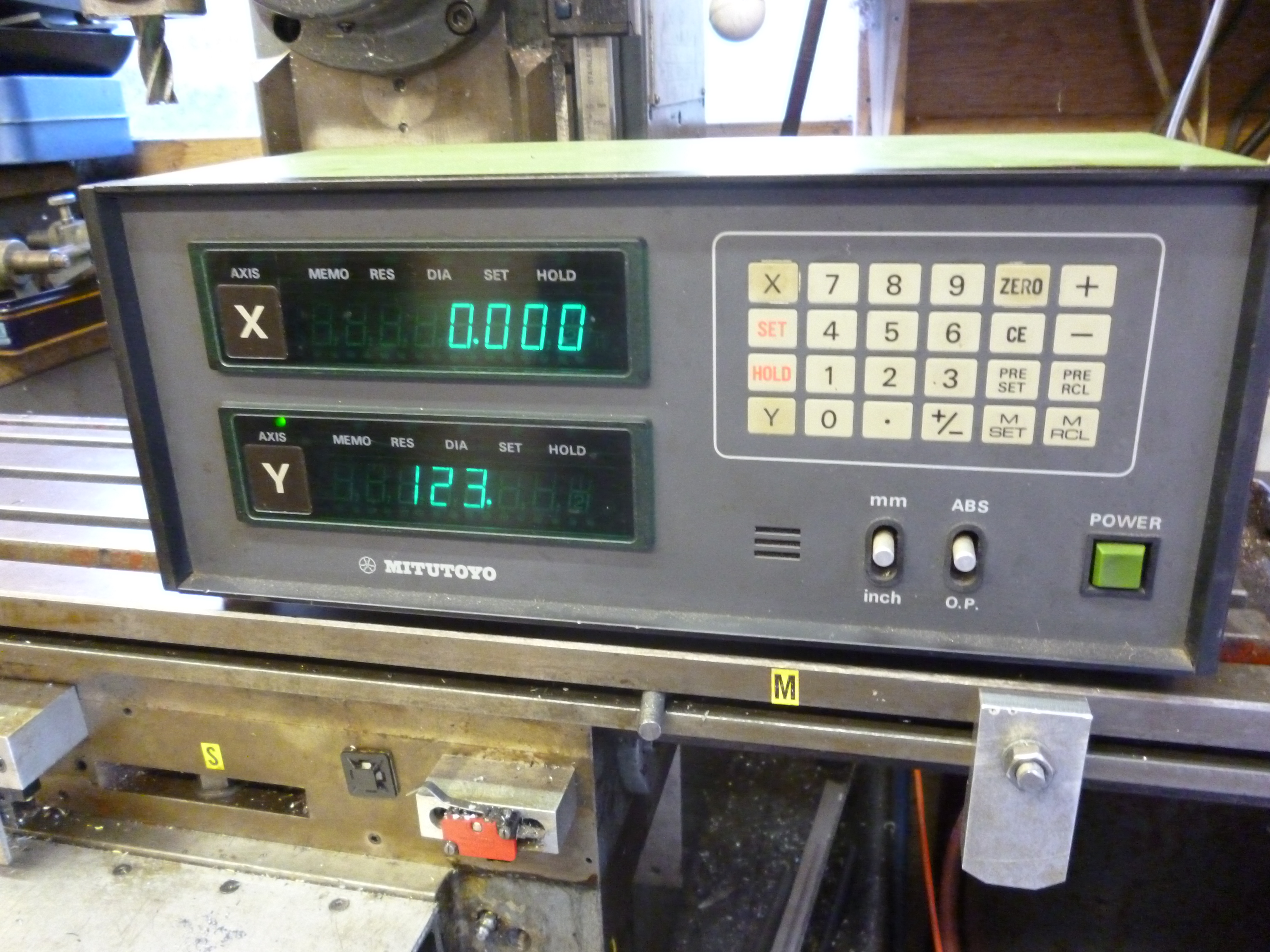
552 Mitutoyo display 2
Fig Mitotoyo DRO display 552
DRO’s – conclusion
It will be found that there are times when the DRO is absolutely indispensable. But much of the time less accurate methods of measuring can be used.
Power
Small milling machines will run off a 13-amp plug using the usual single-phase supply. It is essential that in this case the machine is properly earthed. This should happen through the earth contact in the plug but it is worth checking that there is a continuous earth circuit. The fuse in the plug must be the value recommended by the supplier.
Power switch
On small machine the power will be turned on or off by means of a simple switch.
No volt release
On larger machines the main power switch should have a “no volt release” mechanism. This means that if the power fails when the machine is switched on then, when the power is restored, the machine will not turn back on by itself.
A no volt release system invariably uses a contactor. This is really just a special type of relay. When the “start” switch is pressed power is applied to the solenoid that closes the relay. This then applies power to the motor. But there is an auxiliary contact that applies power to the solenoid as well so that when the finger is removed from the start button, power is still being applied to the solenoid.
However this circuit contains the “off” button. This is a normally closed switch. When the “off” button is pressed the power to the solenoid is turned off and the contactor is released and the power to the motor ceases.
Clearly if the power is turned off elsewhere the contactor is released and nothing will turn it on unless the “start” button is pressed.
Fig. no volt release circuit
Emergency stop
It is essential that larger milling machines have an emergency stop. This stop should be clearly marked and designed to be an emergency stop. Of course, if the machine has a no volt release system then even if the emergency switch is reset the machine will not go back on.
Running the motor in reverse
On some milling machines it will be found that the switch that turns on the main motor can switch it on in either direction. It might seem that since all cutters cut only in one direction this feature has no real use. This is true for most vertical type cutters. But though most horizontal type cutters are symmetrical there are some that are not and there are times when they need tot be used the “wrong” way round and need to be run in reverse.
3 phase supplies
Larger milling machines will be designed to use a 3-phase supply. This used to be a nominal 415 volts but harmonisation with Europe means this is now about 380v.
Many of the larger machines that might be useful in the home workshop were built with three phase motors. At the same time most home workshops will not have three phase power supplies.
If a 3-phase machine is acquired then the choices are:
A To change any motors on it to single phase ones,
B to find a substitute for a 3-phase supply
C getting a 3-phase supply
A The main problem with this is that if the machine has a power feed, or a coolant pump, the motor is often imbedded in the machine in such a way as to make changing it difficult.
B Another alternative is to simulate a 3-phase supply. This can be done in 2 ways. A converter that generates something that passes for a 3-phase supply. These often produce three phases but they are not quite right. The easy way to improve this is to connect a pilot motor to the system that runs all the time though without any load. This improves the output considerably.
Alternatively an inverter can be used. This will give three phases that really are symmetrical.
Most inverters can also be used to control the speed of the motor. However the power available will be proportional to the speed of the motor. If the motor runs at a lot less than it’s designed speed there is a risk of it overheating. This is not really a substitute for a gearbox where the power available will be the same regardless of the speed.
Inverters can also be programmed to provide “soft” starts.
C Getting the local electricity supplier to provide a 3-phase supply. This is usually prohibitively expensive. The price quoted is nothing to do with the cost of doing the job. It is just their way of saying, “NO”.
The easiest solution to this is to use an inverter.
See MEW 93 p20
Coolant tank and pump
On larger milling machines, the base or column of the machine has a tank that can store the coolant. A pump fits into the tank to pump the coolant to the cutter as required.
It is essential, if coolant is used, that it is collected after use and recycled. All of the T-slots on the milling table must be connected so that any coolant that ends up in them can be fed back into the coolant supply tank.
Even so very often, if something hangs over the edge of the table, for example, a large vice, coolant will escape. The ideal solution is to have a tray under the milling table that is big enough to catch any coolant that goes over the edge of the table – wherever the table is.
Small milling machines often do not have a method of supplying coolant to the workpiece automatically.
But it is possible to have a coolant system that runs on a much smaller scale. The coolant is aimed at the workpiece but instead of collecting it using the slots in the table it is collected in a container that is placed directly under the point where the cutting is taking place.
This sort of system is also useful where the coolant is expensive
Coolant does not last forever. It should always be disposed of by taking it to the local tip for disposal.
Coolant systems that rely on flexible joints between steel pipes are a complete waste of time. The best system is the Loc-Line flexible plastic pipes one.

679 LocLine coolant system
Fig The Locline coolant delivery system 679
Safety
When using a milling machine there are many ways in which it can be hazardous. There are two particular ones.
Firstly when milling, much of the metal removed comes off as small, sharp pieces. Often they can also be very hot. They can also be moving very fast and can ricochet off surfaces unexpectedly. Goggles are absolutely essential. Ordinary glasses are not adequate since the bits can hit the skin and bounce round the edges of the glasses and into the eyes.
It is also possible to get guards that fit round the cutter and will stop many chips. Different types of guards are needed for horizontal milling to those needed for vertical milling

1 guard vertical
fig guards for vertical milling

428 guard for horizontal milling 2
fig guards for horizontal milling

Can you tell me where I can get horizontal milling machine guards simi;ar to the one illustrated in your blog. Thanks
They came with the milling machine. I sold them on ebay since I have a serious space problem. If I wanted to buy such things I would look first on Ebay. Most of my stuff has been bought on ebay.
john f
hello i have a elliott sturdymill 1250 horz mill does anyone know how to adjust the clutch thank you
try ebay to buy a copy of the manual for your milling machine. This will probably have part diagrams showing the parts and how they fit together. Then try going to the model engineer website and go to a forum and ask for help. Another good place where you can ask for help is homeworkshop website.
hope the helps
john f
wow very quick response yes i have the maintenance manual yes it shows parts but cant see how to adj thank so much
i am pondering converting a fixed vertical head to a quill type . or by simply buying one