From the lathe to the milling machine
The father of all machine tools is the lathe. Its use can be traced back thousands of years. The milling machine is much more recent invention going back only to the middle of the nineteenth century. It was originally invented to mill the flutes in twist drills. Though it was not developed from the lathe it is easy to see the connection.
The Lathe
The lathe has a horizontal bed. Fixed on the left of the bed is the headstock. Coming out of this, above and parallel, both horizontally and vertically to the bed is the spindle. This is usually driven via belts or gears or both from an electric motor. Various devices can be fitted to the spindle to hold the workpiece. Travelling along the bed is the carriage. This holds the tool. It is designed so the tool can be moved left and right and in and out. The cutting edge of the tool is usually set to the height of the axis of rotation of the workpiece. On the right of the carriage is the tailstock. This can be moved left and right and often holds a center that can be used to support the workpiece. It can also be used to hold tools such as drills, taps, dies and reamers.
A key feature in all of this is that the workpiece is rotating and the tool is, relatively, fixed.
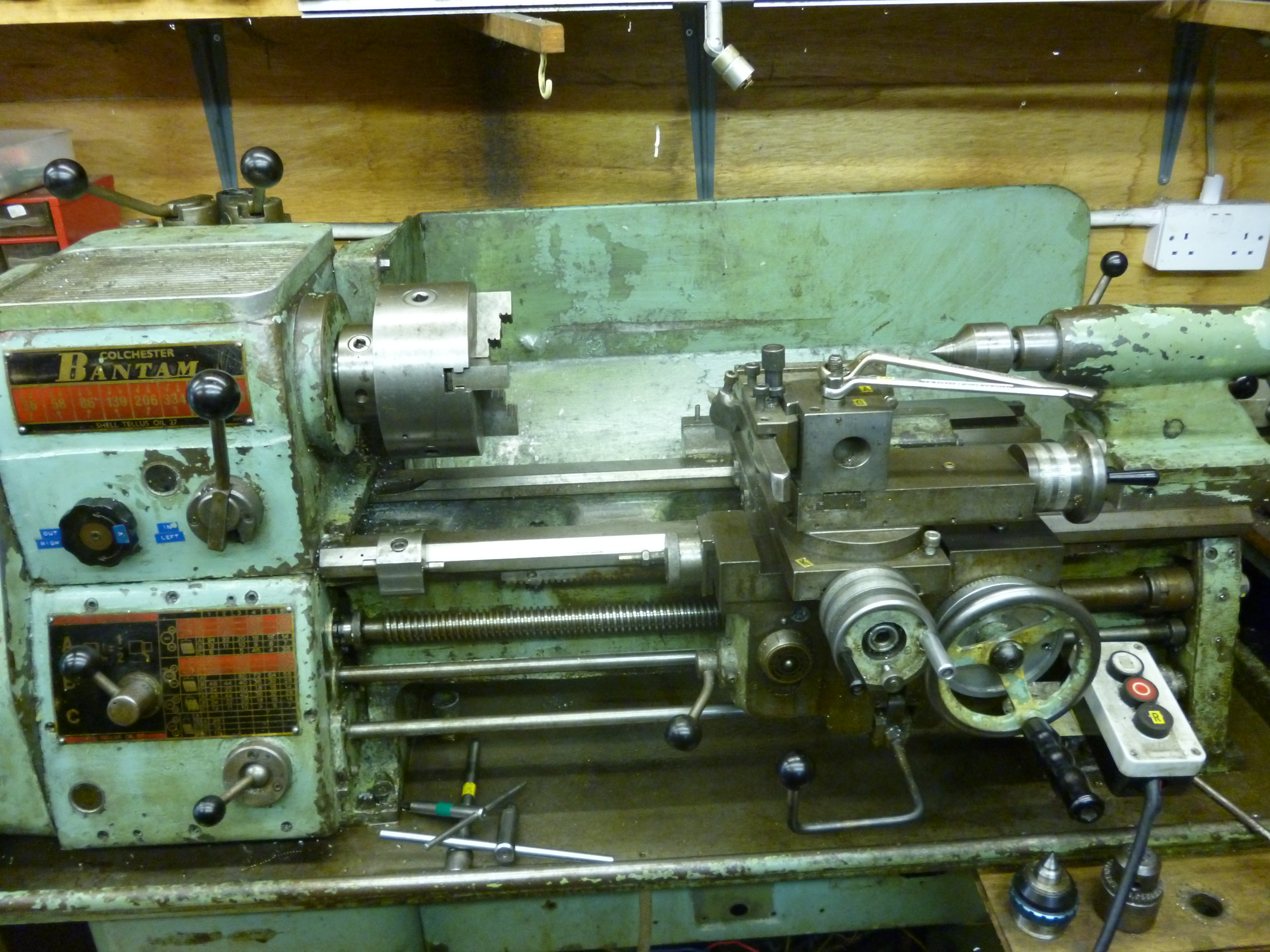
585 lathe
Fig. 1 The lathe 585
If the tool moves along the bed, while the workpiece rotates, then a round surface is produced. But if the tool cuts across the end surface of the workpiece it produces a flat surface. In general it can only produce flat shapes so long as there are no projecting surfaces apart from if there is a round piece in the middle.
The lathe as a vertical milling machine
If we have a lathe and want to produce a square slot, one way is to have a rotating tool held in a chuck and to hold the workpiece in a vice mounted vertically on the cross-slide. Life is much easier if the vice can be moved up and down on a slide.
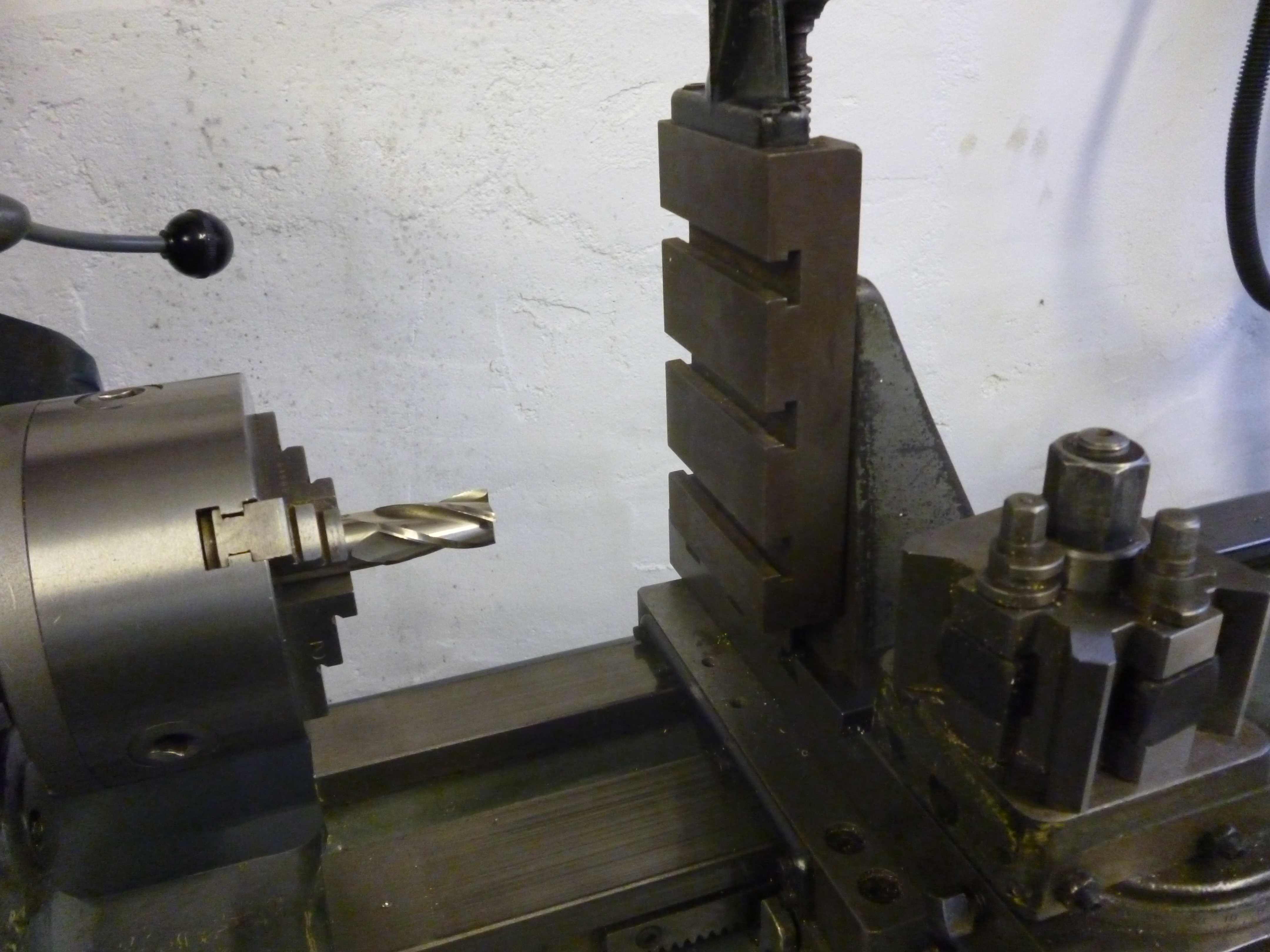
650 lathe used for milling
Fig. 2 Lathe used for milling 650
This arrangement has several serious limitations:
A the conventional chuck cannot really hold a suitable cutter rigidly enough
B it would be much easier to set the position of the workpiece if it was mounted on a horizontal surface.
C though the left/right movement is very large on a lathe it is not very useful if the chuck is holding a tool and the workpiece is held on a vertical slide. On the other hand the in/out movement and the up/down movement are very limited. For any workpiece the maximum length of cut possible in the vertical direction turns out to be equal to the center height of the lathe.
We can solve the problem of holding a milling cutter by fitting a collet chuck in the three jaw chuck and use this to hold the milling cutter.
We can get round B and C if we take this sort of configuration and turn it though 90º so the tool is pointing downwards. A machine like this is commonly known as a vertical milling machine.
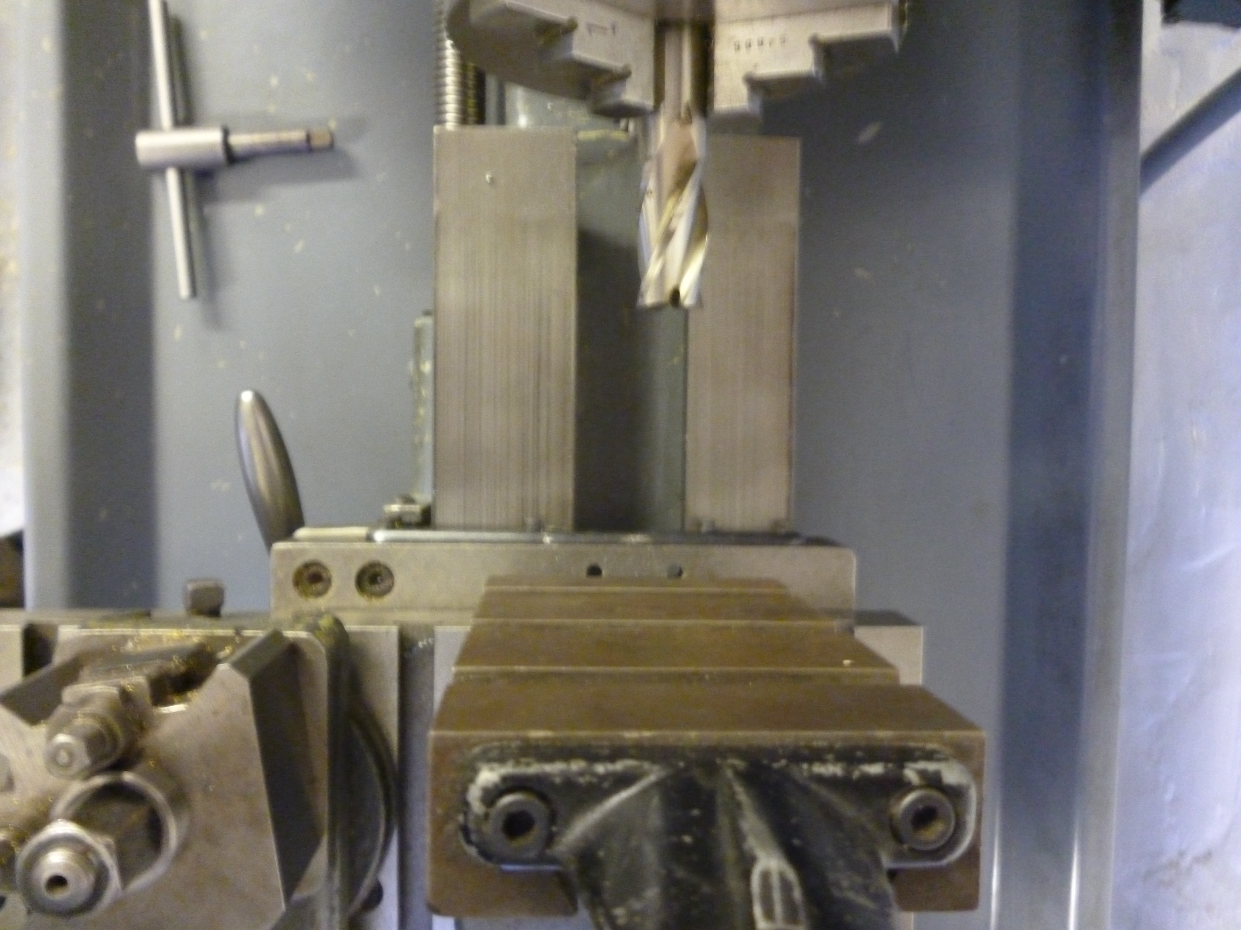
651 lathe as a vertical milling machine
Fig. 3 The lathe as a vertical milling machine 651
(Some readers might have noticed that this is the same setup as in the previous photo but taken from above.)
This is not to say there are not other and better ways of milling on a lathe but that is not what is trying to be shown here.
The following Fig. is of a conventional vertical milling machine. The similarity to the lathe as a milling machine is self-evident.

653 vertical milling machine
Fig. 5.1 A vertical milling machine 653
It will be noticed that the facility for a lathe type chuck has disappeared. Since we only need to hold tools of known sizes we do not need a flexible chuck as on the lathe but a collet chuck specially designed to hold milling tools. The vertical slide has gone and we just have the slide but it is much larger. It is replaced by facility to move the whole of the milling head up or down the round column. It is also possible for the milling cutter to move a smaller distance up or down inside the milling head.
We can, of course, fit a vice to this milling table but with this large table we can do many other things that would never have been possible on the lathe. This table can be moved left/right, in/out and up and down.
We will refer to the left/right movement as the x-axis, the in/out movement as the y-axis and the up/down movement as the z-axis.
If we are using the lathe as a vertical milling machine rotated through 90º then the z-axis is moving left and right. But on this lathe the headstock is fixed and the workpiece moves in the z direction when the carriage on the lathe moves left and right. On some real vertical milling machine only the table can move along the z-axis. This is equivalent to the carriage moving on the lathe. On others both the table and the tool can move in the z direction.
The lathe as a horizontal milling machine
If we go back to the lathe being used as a milling machine it is clear that instead of having a vice on the vertical slide we could have an angle plate. We could fit a vice to this so a workpiece could be cut on its horizontal surface using a circular cutter held in an arbor which was held in the chuck. If we look at the vertical milling machine with its horizontal table it is easy to see that if we keep this and we add a horizontal arbor that could hold a rotating cutter then a whole new set of machining possibilities come into being. This is the horizontal milling machine.
Fig. 5.2 – the lathe as a horizontal milling machine
Fig. 6 horizontal milling on a vertical milling machine 340
In practice it is possible to buy machines that are just vertical milling machines. One of the best-known examples of this is the Bridgeport. It is also possible to buy horizontal milling machines that are designed to be used primarily as horizontal machines. However on the horizontal milling machines it is often possible to add a vertical head or to replace the horizontal arbor with a vertical head. This makes it possible to use it as a vertical milling machine.
Sometimes a machine that can be used as either a vertical or horizontal machine is referred to as being a universal milling machine. But this is not correct. A universal milling machine is a horizontal machine on which the table can be swivelled. (It is easy to see that a swivelling table is of little use on a purely vertical machine).
For the amateur the lathe has to be to be the essential machine tool. The lathe is the king of machine tools because it can, in many cases, sometimes with lots of effort, be persuaded to do jobs that would be better done on some other type of machine tool. But the next most essential machine tool has to be the vertical milling machine. For most amateurs the vertical milling machine has to be overwhelmingly more useful than the horizontal one. However there are some jobs that can only be done with a horizontal machine and there are others that are much more easily done with a horizontal machine. There are even some milling operations that, in some circumstances, are best done on a lathe.
Both of these types of milling machine are going to be covered here. But one of the most interesting types of problems that face the amateur is how to do a job that is really best done on one type of milling machine when he only has the other.
Digression – the mill/drill
There is one common sort of milling arrangement that has not been mentioned. This is the mill/drill. This is simply a drilling machine modified so it can be used for milling.
The standard drilling machine consists of a rotating spindle pointing downwards and a
flat table to put the workpiece on. All that is needed to be able to use it as a vertical milling machine is to fit an x/y table on its worktable. An endmill can be held in the chuck.
There are some problems if this was all there was to it. Firstly the forces when drilling are largely downwards. When milling, the forces can be in any direction at any time. The spindle bearing are designed to take longitudinal forces but not radial ones. The drill chuck will hold an endmill but not very reliably.
If a drilling machine is made more robustly and with suitable bearings and a chuck that can hold an endmill reliably along with an x/y table it can be used for milling. This scheme is very popular. Most are made from plans that are designed so they can be made on a lathe in a home workshop.

652 a mill-drill
Fig. 7 A mill/drill 652
