go to the page above this one – lathe – links
The lathe – description
The lathe – origins
The most primitive lathes consist of two centres, which hold the workpiece. A center, in this sense, can be as simple as a piece of wood with a point on it or even the pointed end of a nail. These centers would be external, that is, male, they would fit into female centers. The workpiece, usually made of wood, would have females centers punched into the wood in the center of either end. The two external centers, on the lathe, would fit the two female centers on the workpiece. This can be rotated by means of a loop of string going round it moving two and fro. This could be done by means of a bow on which the string was wrapped round the workpiece.
The workpiece could only be cut when the workpiece was turning towards the operator. It would be cut using something like a conventional chisel. The operator would bow with one hand, hold the handle of the chisel with the other hand and use his feet as a guide for the cutting end of the chisel.
An improved version of this has one end of the string could be attached to a long pole fixed in position at the far end. The string was then wrapped a few times round the workpiece and then attached to a treadle. As the foot pushed down the workpiece would rotate. When the foot was lifted the pole would act as a spring and pull the string back.
These systems lack rigidity and so can only be used on soft materials like wood and to make shapes that do not have to be very accurate.
The modern lathe
In order to make metal parts accurately the lathe has to be very rigid. The only materials suitable for this are steel and cast iron.
The backbone of the lathe is the bed. This is invariably made of cast iron. This carries the ways. These are the precision machined and often hardened and ground flat surfaces along which the rest of the lathe is fitted or along which parts of the lathe move.
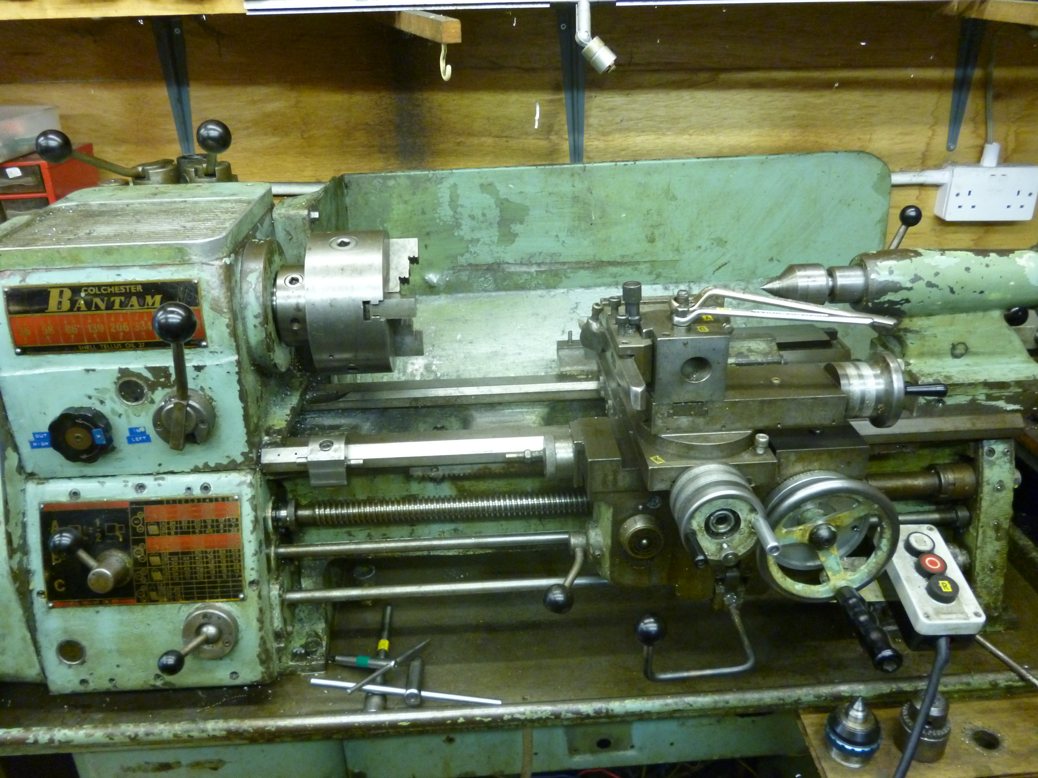
585 lathe
On the left of the user is the headstock. The functions of the headstock are to hold or hold one end of the workpiece and to rotate it. This seems very simple to do, but to do this accurately, reliably and in a way that is convenient to the user makes the headstock rather more complicated.
The headstock has to have a spindle that rotates. The spindle has to be absolutely rigid so there is no play axially or radially. It has to be absolutely parallel to the ways on the bed in both the horizontal and vertical planes.
The end of the spindle has to have some means of holding the devices necessary to hold the workpiece. This is often a Morse taper. This is often used for holding a center. The spindle also has a threaded part or other system for holding a chuck, which can then be used to hold the workpiece.
It is essential for the user that the spindle can be rotated by an electric motor and at a variety of speeds. This can be done using belts and pulleys but it is much more convenient to use gears.
Many users will want to use the lathe to cut screw threads. This can involve many more gears to drive a leadscrew at various speeds relative to the speed on the spindle.
The leadscrew can also be used to drive the saddle along simply to save the user having to do this on a long or repetitive cut.
Mounted on the ways of the bed is the saddle. This is mainly used to hold the cutting tool. The saddle can be moved along the bed manually or by means of the lead screw that is driven by the spindle. The saddle has a slide that can be made to move at right angles to the bed. This is the cross slide. There is then a second slide mounted on the first that can rotate but is usually aligned with the bed of the lathe. This is the top slide. Mounted on the top slide is the tool post. This has some sort of arrangement for holding a toolholder that finally holds the cutting tool.
The last major component is the tailstock. This can be slid along the bed of the lathe. It contains a round barrel that does not rotate but can be feed out in a controlled manner. This barrel has a Morse taper in it. The axis of the barrel has to exactly coincide with that of the spindle. The tailstock can be used to support the workpiece, with a center, or to hold tools such as drills that can be used on the workpiece.
The lathe – details
The bed
The bed holds the headstock at the left end. On the right is the tailstock. In between is the saddle.
A lathe cannot do accurate work unless its bed is flat and straight.
This is usually done by setting the bed so it is horizontal both along its length and at several points across its width.
Though all lathes might start life like this as they are used they are likely to get worn. If the wear was even all over it could be adjusted for. But, of course, most the wear will occur at the point where the saddle is used most.
If the bed is hardened it will not show any signs of wear for a very long time. On the other hand, even a hardened bed can become corroded if it is not looked after. It might be thought that a small hole would be of no significance. The problem is that any noticeable hollow on one of the surfaces will catch very small bits of swarf. Though the bed might not wear the underneath of the saddle and the tailstock can.
It is possible to design the bed so if any wear occurs it is of less importance than it would be otherwise. One way of doing this is to guide the saddle using a V-shape along one side of the bed.
Fig the v-shape
If this wears the height of the saddle falls. And if the height of the saddle goes down it does not have the same effect as if it moves in or out as would happen if the bed was flat and the saddle was held in place by the edges of the bed.
The arrangement that is often used is for the saddle to use a V-shape on one side and a flat surface on the other. Since the same principles also apply to the tailstock this also has a V-shape on one side and a flat on the other.
Once a bed has been worn in an unacceptable manner it is possible to have it reground. In most cases it is probably cheaper to buy another lathe.
Gap Beds
Some lathes have what is known as a gap just in front of the headstock. Of course it is not really a gap but a U-shape in the bed of the lathe.
Fig gap bed
Gap bed lathes are supplied with a piece that fills the gap when not needed but on many older lathes the thing for filling the gap might well have got lost. The lathe can still be used without the gap piece.
The gap is not long. In fact either a three or four jaw chuck will reach right over the gap. So the gap will only be able to take workpieces if they are held on the faceplate.
The point of the gap is that thinnish workpieces can be turned of much greater diameter than would have been the case without the gap. An obvious example would be large diameter driving wheels.
The gap works because when a chuck is being used the chuck is longer and “fills” the space over the gap so the saddle is fully supported even when machining right up to the face of the lathe.
The length of the bed
Many lathes often supplied with a standard length of bed or with an extra long bed. It will usually be found that the diameter of the work piece is more of a limit to what one lathe can do than the length of the bed. A longer bed, for most users, is of limited value. If we consider that for most users there is a shortage of space then a longer bed becomes a liability rather than an asset.
The headstock
The spindle is held in two bearings one of at either end of the headstock. These bearing have to take all of the forces exerted on the workpiece. These forces may be either radial and/ or axial.
These bearing may be either made of solid metal such as bronze or they may be ball or roller bearings. Either way the bearings usually contain a tapered component so that if the bearings are forced together any play is taken up. The front bearing is usually fixed in position. There is then some nut or similar at the back of the spindle that can be used to tighten the bearings. This nut should be tightened to just before the point where the spindle is no longer free to rotate freely and then backed off very slightly till it does rotate freely but without any play.
If this is done there will usually be no radial or axial play in the spindle.
For these bearings to work properly and have a long life, cleanliness and proper lubrication are essential.
Holding workpieces with the spindle
Holding workpieces is covered in detail elsewhere. Here it is mentioned simply to outline features the headstock needs to be able to do this.
There are two features necessary on the spindle in order to be able to hold workpieces.
Firstly, at the front end of the spindle the spindle is fitted with a Morse taper. The main use of this is to hold a center. This is essential for holding a workpiece between a pair of centers where the other center is in the tailstock.
Fig a center

5069 spindle fitted with center
Fig spindle fitted with a center
Whenever a center is used both the taper in the spindle and the taper on the center must be absolutely clean.
Secondly,the front of the spindle also has to have some means of holding a chuck or other work holding device. Very often this is done using a male screw thread. The work holding device will be aligned in the plane at right angles to the axis of the spindle by a flat surface. It will also be aligned with the axis of the spindle, not by the thread, but by a shoulder.
Fig nose of the spindle with a screwthread
With this sort of fixing the chuck etc is screwed on and tightens. Needless to say the force applied by the cutter to the workpiece only further tightens it.
Unfortunately if the workpiece runs in reverse the opposite is the case – enough force will loosen the chuck. Often, when the lathe is supplied there is nothing that can be done to prevent this happening.
An alternative way of fixing a chuck is for the nose of the spindle to be fitted with a flange. This flange will have some means of aligning a chuck There is then a set of holes for bolting the chuck onto the flange.
fig Emco lathe with a chuck that is bolted on
This means the lathe can be run in reverse. But changing the chuck is very time consuming. The problem with this is not that the user wastes a lot of time changing chucks. The problem is that he does not. He will, if one chuck is fitted but he needs another, try and use the first instead of the second. The result will invariably mean that the job is not done properly.
There are many occasions where it is useful to be able to run a lathe in reverse. One way of making this safe is the Camlock system. Here the chuck is aligned by means of a short taper on the spindle. It is then locked on by a number of pins. A cam mechanism it used to hold the pins on the chuck into the holes on the spindle.
On a small lathe there might be only 3 pins but the number goes up as the spindle gets larger. A camlock fitting is a series of American lathe noses classed as “D1”. This is followed by a number, for example D1-3, where the 3 is, roughly the diameter of a circle that encloses the pins, in inches.

5070 camlock fitting on chuck
fig
The bore of the spindle
The spindle is always hollow. The diameter of this bore is quite important because it often means a very long workpiece can be held if it can fit into this bore.
Gearing for spindle speed
There is usually some means of changing the speed at which the spindle rotates. This can be done with belts or with gears or a combination of both.
With early lathes the speed was changed using flat belts acting on different size pulleys driving the spindle. One early innovation was the back gear. This was an arrangement whereby the speed could still be changed using the belt but the result of this could be reduced by a simple arrangement of gears. This can be seen on a large lathe made by Roberts of Manchester in 1817, which can be seen in the Science Museum in London.
On modern, better quality lathes all of the spindle speeds can be selected by changing gears.
On smaller lathes it is quite common to use a variable speed motor to control the speed of the spindle.
Turning the spindle by hand
It is often useful when setting up a workpiece in a chuck or on a faceplate, to be able to rotate the spindle by hand.
If the spindle is setup to revolve at a high speed, if the power is off, it can be rotated by hand. On the other hand, if it is set to a low speed it cannot be easily rotated by hand.
If the lathe uses belts then if a pulley can be moved to loosen the belts, so as to change “gear” it can be used to put the drive in “neutral”. If gears are used it is usually possible to put one gear lever between the two engaged positions to put the machine in neutral.
Gearing for driving the leadscrew
Most larger lathes have a leadscrew for moving the saddle. This is essential for cutting screw threads. Since we often want a wide range of thread pitches we need a means of controlling the speed of rotation of the leadscrew relative to the speed of rotation of the spindle.
This is often done in two stages. The first is a flexible arrangement of gearing that is set up by the user. Sometimes these gears are all that determine the thread pitch. In this case quite a lot of gears might be needed. These will drive the leadscrew directly.
Alternatively, the output of this set of gears is then fed into a gearbox where another selection of gears can be made by simply moving a lever. the output of this gearbox then drives the leadscrew.
The leadscrew
Since the leadscrew is used to move the saddle when cutting threads, the accuracy of the leadscrew is very important. Even if it is accurate when made if it is used it will suffer from wear.
Though cutting screws might use the leadscrew only occasionally very often, on cheaper lathes the leadscrew is also used to feed the saddle. On better lathes there are two rotating parts. One is the leadscrew for moving the saddle when screw cutting and the other is a rotating rod for driving the saddle when just turning.
If there is a separate leadscrew there is usually a dog clutch to stop the drive to it when it is not in use.
Leadscrew – Metric/Imperial
The leadscrew will be either metric or imperial. If it is necessary to cut metric threads on an imperial lathe or to cut imperial threads on metric lathe then it is usual to need some extra gears between the drive from the headstock and the leadscrew.
Since there are 25.4mm exactly in one inch (by definition) and since 25.4 x 10 can only be divided by 2 to give 127 this is the magic number required for conversion. Since such a gear is large it is expensive. But it is often too big to fit a small lathe. It is possible to use other approximations depending on the accuracy required.
Tailstock
The tailstock fits on the right hand side of the bed of the lathe.
The tailstock has three main types of use. The first is to support the workpiece that is being held and driven by one means or another from the spindle. The second is to hold some sort of tool which will be used on the workpiece mounted by some means at the headstock end of the lathe. The third is where the workpiece is “held” at the tailstock.
The tailstock is made to be at the same center height as the spindle it does not have any means of adjustment. Very small errors here will have a negligible effect when turning. The tailstock can be adjusted laterally so that the axis of rotation of a workpiece between centers will be parallel to the bed of the lathe, This is essential.
The tailstock can be locked onto bed at any position along the bed.
The tailstock contains a barrel that can be screwed in and out. It can be locked at any position. The end of the barrel, facing the headstock, contains a Morse taper. There is no hole through the center of the barrel.
The barrel is often graduated so its movement can be measured. This is often useful but it is not very accurate.
Tailstock – supporting a workpiece
The tailstock is often used to hold one end of a workpiece held by a center held in the tapered socket in the tailstock’s barrel. The workpiece has to have a center cut in its end and the tailstock has a center in it.
fig the tailstock
Centers that can be used in the tailstock are of two types – a dead center that does not rotate and a live center – a point that if free to rotate. The dead center is the same as that used in the headstock.
fig a live center
In practice, a dead center is always used in the headstock, but though a dead center might be used in the tailstock, in the vast majority of cases a live center is always used in the tailstock.
The usual procedure is to mount the workpiece in the chuck. A center drill in a drill chuck is mounted in the tailstock. The tailstock is pushed till the center drill nearly touches the workpiece. The lathe is turned on. The tailstock is locked in position. The tailstock’s handle is turned so the center drill cuts a center in the workpiece.
The drill chuck is removed and replaced with a live center. The handle is turned till the center is tight against the workpiece. The barrel is then locked.
If, when the lathe is running and the live center in the tailstock is not rotating the center is not being pushed into the workpiece hard enough.
If during a job the center, which was rotating, stops rotating the most likely cause is that the workpiece has been pushed into the chuck.
Tailstock – mounting a tool
The tailstock can be used to hold all sorts of tools that can be used to machine a workpiece mounted in a chuck or on a faceplate in the spindle. Examples are:
A drill chuck, which can hold:
A center drill
A drill bit
A tap
A reamer. It is better to mount a reamer in a floating holder in the tailstock.
A die holder
Tailstock – “holding” the workpiece
The tailstock can be used to hold a workpiece. In this case the tool is mounted in the headstock.
One example is to have a drill or reamer with a tapered shank mounted in the headstock spindle. The workpiece is held against the flat of the tailstock. This can be useful when either the drill or the workpiece will not fit on the drilling machine.
The taper in the spindle is often larger than the taper in the tailstock. So this is often defines the largest size drill that can be used.
If the center is removed from the tailstock, the barrel in the tailstock presents a flat surface. On a larger lathe a piece of wood can be placed against this.
It is possible to get a part with a taper that fits the tailstock barrel. The front of it is a round flat surface. It is good for supporting flat surfaces of workpieces that are to be drilled. Often these have a 90-degree groove in them for holding round workpieces. This groove is on the centerline of the lathe and so can be used for cross drilling round workpieces.
The saddle
The saddle sits on the bed and can move left or right. This is the prime way of moving the cutting tool left or right.
The saddle usually has some means of locking it in any particular position.
On most lathes there is a leadscrew coming from the headstock that goes through the saddle. In the saddle there is a system of halfnuts that can engage the leadscrew. This means that if the halfnuts are engaged and the leadscrew is rotating this will drive the saddle along. This can be used to cut a long, round surface or cut a screw thread.
Some lathes have the ability to use this feed to drive the cross slide across instead of driving the saddle along. This is useful for facing workpieces.
The accuracy of the leadscrew limits the accuracy of any thread cut. If there is wear on the leadscrew this reduces its accuracy. One way round this is to reserve the use of the leadscrew just for cutting screw threads. For anything else there is another shaft coming from the headstock that is used to provide power for moving the saddle left or right or for moving the cross slide in or out.
The saddle carries the cross slide.
The cross slide
This is the prime way of moving the cutting tool in and out.
Usually the cutting edge is being pushed against the work piece. This takes up any play in the leadscrew/nut system for the cross slide. So long as the force is always this way, the dial on the cross slide will give an absolute reading of where the cutting edge is, even if it is pulled out and then pushed back.
If the inside of a hole is being bored the same is true but the force is in the opposite direction.
The cross slide does not usually have a lock.
The cross slide carries the top slide. This is between the user and the workpiece.
The cross slide can also carry a tool post on the far side of the workpiece.
Some cross-slides have a set of T-slots in them. One common use for these is so a vertical slide can be fitted so the lathe can be used for milling.
The top slide
The top slide usually holds the toolholding system. The top slide can be moved left or right. It is calbrated so movement of the cutter in the left/right directions can be accurately controlled. But the top slide has the special feature that it rotates. This is useful for turning tapers. But it also means that whereas movement in the left/right direction using the saddle is always parallel to the bed of the lathe, movement using the top slide is not usually as accurate unless it is specially set up to be so.
Because it is often rotated and then put back, it has only been aligned using the graduations at its base. Because of this it can never be relied on being able to produce perfectly parallel surfaces. When the best possible parallel surface is required this should always be done using the movement of the saddle not the top slide. The saddle also moves more smoothly and can do so for longer distances than the top slide.
If a taper of angle x needs to be made then there are two ways round that the top slide can do this. It is also useful if the shape of the work piece is such that the tool cannot get at it when the tool is in its usual position.
The top slide also has the interesting property that if its dial is calibrated in say, 0.01 of a mm then if it is turned to an angle of 6 degrees, turning its dial by one space will move the cutting edge only one tenth of what it says, in this case, 0.001mm. For this to work the tool must be sharpened and honed to the finest finish possible. The tip of the tool should be a smooth round shape as far as possible.
It is sometimes argued that the top slide is not that necessary. If it is removed a tool post can be fitted directly onto the cross slide. This has the advantage of being more rigid.
The top slide does not usually have a lock.
Most top slide have a T-slot cut into them. This takes what can best be described as the tool post stud.
The tool post stud
The tool post stud can be described as being a special form of T-slot bolt. It fits the T-slot on the top slide.
fig T-slot in the top slide
fig tool post stud fitted to the top slide
Usually a toolpost is bolted on to the top slide using this stud. This then takes a toolholder. However it is possible for the tool holder to be just a lump of metal with a slot in it to take a cutting tool. This is bolted on to the top slide using the tool post stud. The cutter is fixed in by means of cap screws. Often special screws with square heads are used for this.
Fig – simple tool post
The height of the tool holder is set using packing bits. This takes time and needs to be done each time the cutter is changed.
Four way toolholder
One way round this is to have a square toolholder with a slot all the way round it so there are four spaces to hold tools. Each one of these can be adjusted for height separately. By rotating the tool holder any one of four tools can be selected. Each of these tools will have to be set to the right height by using packing pieces. Apart from this there will be many tool holders the might not fit a rotating tool post.
Fig – four way toolholder
If a four way toolholder is held by a simple bolt then, each time it is turned, the tips of each cutter will never be at the position.
The tool post can also be made so that a quick change tool holder can be fitted to it. This can then hold any one of any number of tool holders. A tool holder designed for one type of tool holder will only hold that type of tool holder. The most common type of quick change tool holder is the Dickson. Even with this type there are several ranges of size and a tool post will only take the one size.
Fig – quick change tool post
It is quite easy to make a quick change toolpost in the home workshop. It would be hard to believe that anyone who has used a quickchange toolpost would ever go back to anything else for most work.
Some people recommend a three way toolpost
Three Way Tool Post – Dave Lammas
MEW no 27 p56
Kelly toolpost
Gibraltar toolpost
The rear toolpost
The cross slide can also carry a rear toolpost. This has two different uses. The most common is for holding a parting tool. This is because there are advantages in using a parting tool in this position. The second is that it provides another cutting tool without the need for changing the toolholder in the front toolpost. This can be useful when using the capstan.
The other tool that can be usefully held in the rear tool post is a chamfering cutter.
The rear toolpost can be used with the lathe rotating in the usual forward fashion. In this case the cutting edge must upside down. It can also be used with the lathe running in reverse. In this case the cutting edge must be right side up.
Stops
When making many cuts to the same distance on a workpiece or when making more than one copy of a part it can save a lot of time if the movement of the carriage and cross slide can be limited at certain points. This is done by means of stops.
Single stops
A single stop is simply a clamp or other mechanism that stop the movement of the saddle or the cross slide.
The most useful and hence the most common is a simple saddle stop which is just a clamp that clamps onto the bed of the lathe to the left of the saddle.
Often a workpiece must be reduced in diameter up to a certain point. This point is set by the stop. It is then easy to do however many passes are needed to reduce the size without any risk of going too far.
Multiple stops
If many parts have to be made with several diameters cut to different lengths then it is useful to have some system of stops. Each one would be used for each different length.
Very often stops can be rotary devices with several different stops of varying length. In this case stop, say, 4 on the saddle will be used in conjunction with stop 4 on the cross slide.
If a set of stops is used to determine limits of cutting on a work piece it is quite useful to also use a stop to set the end of the work piece at the beginning of each one. This can be done by moving the tip of the cutting tool to a particular position and this pushes the material into the chuck to a certain point where the chuck is then tightened.
Having machined this workpiece it is then possible to use another stop to define where the workpiece is to be parted off.
More accurate stops
If it is desirable to get the better accuracy then it is possible to get a micrometer stop. This can be adjusted to 0.02mm or 0.001 inch.
fig – micrometer stop
With most stops, if the saddle, say, is pushed hard enough it will move a bit more. This can be improved by the probe on the stop not hitting a piece of metal but touching a DTI. This will give accurate readings.
fig use of DTI as the fixed part of a stop
This can be used to stop the movement to within 0.001mm or 0.0001in ie one tenth.
It is also possible to limit how far the workpiece will go into the chuck by means of a stop that fits into the lathe’s spindle.
The stop is set so that when the table just touches the stop it is a few hundredths short of the required position. The handle is then turned more firmly until the required position as shown on the DTI is reached. In the example the stop is on the quill, which is, of course, effectively, the z direction table stop.
Fig. 2.4 – DTI being used in conjunction with a “table” stop
DRO’s on a lathe
On a lathe dimensions along the length of the lathe are seldom critical whereas diameters are. One solution to getting this right is the use of a DRO.
This does not mean that just getting to the final size on the DRO will get everything right.
