go to the home page
go to the page above this one
Lathe – workholding – two, three and four jaw chucks
The three jaw chuck is probably the most common way of holding a workpiece on the lathe. It is very quick and easy to use. But it can only hold round, triangular and hexagonal workpieces.Though it is quite accurate it is seldom as accurate as the four jaw chuck can be but for many jobs it is accurate enough.
These are both covered on this page because they have several features in common as well as several important differences
Almost always both the three jaw and the four jaw chuck would be used fitted to the spindle in the headstock to hold a workpiece. But there are a few occasions when they could be used to hold a tool or even be fitted to the tailstock
In all the cases here the chuck is being used with the lathe. There are other pages where these chucks are used in other ways on other machines.
Fitting a three or four jaw chuck to the spindle
A three or four jaw chuck can be bought without any means of fitting it to the spindle.
fig three jaw chuck without fitting for a spindle
fig a four jaw chuck without any fitting for a spindle
In either case a back plate that fits the spindle has to be fitted to the chuck before it can be used on the lathe.
It is also possible to buy a three or four jaw chuck that is specifically made to fit a certain type of spindle. In this case the length from front to back may be less but the chuck will only fit the spindle type it was made for. There are some types of fitting where chucks etc are always made to fit this type of spindle.
Position of bolts holding chuck on backplate
Inside a three jaw chuck there is a scroll that takes up almost all the space. Clearly where the scroll is there cannot be any bolts. Therefore, on the three jaw chuck the bolts are right round the very edge of the chuck. Consequently the diameter of the backplate is the same as the diameter of the chuck.
With the four jaw chuck there is no scroll and the bolts holding it onto the backplate can be positioned in a more convenient manner. This means about halfway between the edge and the center. The size of a suitable backplate can be significantly smaller than the chuck it fits onto.
Backplates
Backplates can be bought as blank castings.

1227 casting for a backplate
fig casting for making a backplate
In most cases they are held onto the spindle by means of a screw thread. However this thread merely holds it on – it does not align it with the spindle. The alignment is done by means of a small flat surface and a parallel shank then comes the thread.
fig typical nose for holding a three jaw chuck (this particular one is on a dividing head)
If the casting is held as shown in a three or four jaw chuck as shown then the surfaces needed, save one, can all be made all with the casting in one position.
fig holding the backplate for turning
The front is turned flat. It is center drilled, drilled and tapped. It is then turned to provide the hole needed for the parallel shank. The fit here will be a limiting factor in the accuracy of the chuck.
fig facing
fig after drilling and tapping
fig after boring
Having done this it is now possible to mount the back plate on the nose of the spindle. Since it will now fit as it will finally be used this is very accurate. The front of the backplate can now be turned.
It will be noticed that, on all chucks, the the back of the chuck has a recess in it.
fig recess in back of the three jaw chuck
The inside edge should be coaxial with the axis of the chuck. So the back plate should be turned so that when the chuck is fitted a protruding part of the backplate just fits into this recess.
fig part of backplate that fits into the recess on the back of the chuck.
Again, the accuracy of this limits the accuracy of the chuck in the case of the three jaw chuck, but this makes no practical difference on a four jaw chuck.
Accuracy of three jaw chucks
For a three jaw chuck to be accurate it must, when holding a round bar, hold the bar so that its axis is concentric with the axis of the spindle.
There are two types of error possible here.
If a piece of ground round stock is fitted to the three jaw chuck and is tested with a dti it will usually be found to be few hundredths out. In many cases this is quite acceptable. This error can vary according the wear on the scrolls in the chuck so the error might be different for workpieces of different diameters.
Three jaw chucks are seldom accurate enough to assume that a round bar will be held concentric with the axis of the spindle. But if a workpiece is held in a three chuck that is off center any surfaces turned on it in one go, i.e. without removing it from the chuck, will all be concentric relative to each other and to the axis of rotation of the spindle.
This means that a workpiece can be made with any number of round surfaces all of which will be concentric. This feature is the key to turning between centers. But if, for some, reason, the workpiece is being held in a chuck then it is not possible to turn the surface that is being held. So it usually means that the part can be made but then has to be parted off.
The workpiece has to be big enough so that it can be turned down to the size needed. It also follows that, we cannot use any existing surface on the final workpiece – it will be eccentric to any we now turn on it.
Three jaw chuck – the jaws
On three jaw chucks used for metalwork the jaws are always self centering. Each jaw has teeth in it.
fig the teeth
These teeth engage a scroll inside the chuck. If a jaw is removed it is possible to see a small part of the scroll inside the chuck.
fig a small part of the scroll
The chuck key turns the scroll and all three jaws move in or out together.
For this to work each jaw has a slightly different position for its teeth. Each jaw is mark 1, 2 or 3. These jaws have to be fitted to the right slot on the chuck. These, too, are marked 1, 2 and 3. It is essential when fitting the jaws that jaw 1 is fitted first. Turn the chuck so slot 1 is at the top. Use the chuck key to turn the scroll forwards till the start of the scroll has just gone past the slot and then turn it back so it is just on the far side of the slot. Put jaw 1 in the slot and turn the scroll forward till jaw 1 is engaged. Turn the chuck away from you till slot 2 is on top. Turn the key till the start of the scroll appears. Put in jaw 2 and just turn the key till the scroll engages jaw 2. Do the same for jaw three. This is necessary so that the front edge of each jaw is exactly the same distance from the axis of the chuck as the front edges on both the other jaws and at whatever distance they all are from the axis of the chuck.
THE CHUCK KEY MUST NEVER BE LEFT IN THE CHUCK EXCEPT WHEN IT IS ACTUALLY BEING USED TO DO UP OR TO UNDO THE WORKPIECE.
It should be sufficient to use just two hands at most to tighten a chuck with the right key.
Three jaw chuck – types of jaws
A three jaw chuck is normally provided with two sets of jaws. One set is the internal jaws.
fig internal jaws
These can be used so the long edges are holding the work piece on its outside surface. They can also hold a workpiece using the stepped faces on the inside of the workpiece.
The other set is the external jaws.
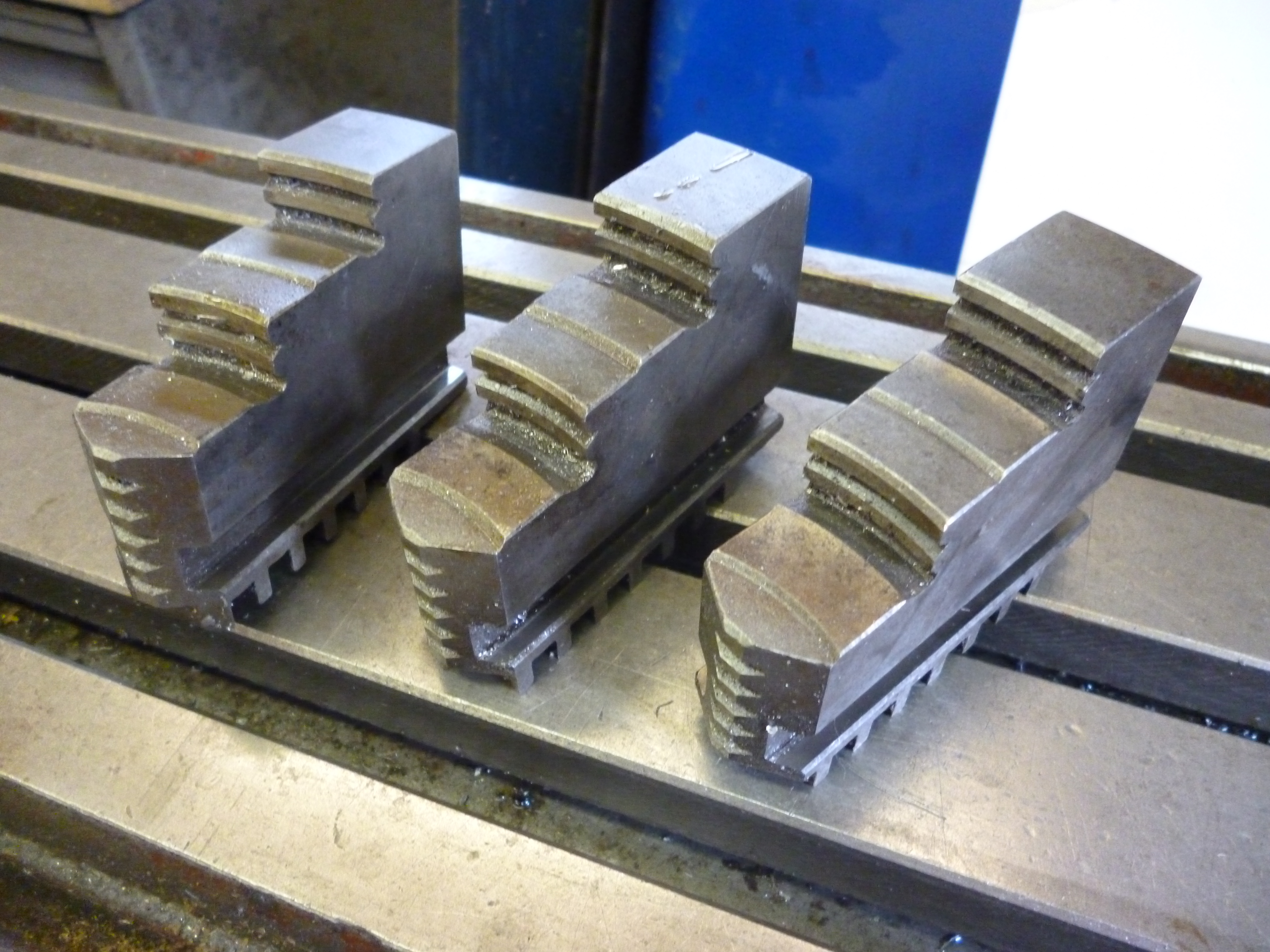
1200 external jaws
fig external jaws
On these only the internal stepped edges are ground and are intended to be used to hold the workpiece so the workpiece is , with these, always held on an external surface.
These usually hardened and ground and so have to be used as they are.
The terms “internal” and “external” might not seem logical. The way to see this is by considering the case where a piece of large diameter tubing has to be held. The internal jaws will hold it on the internal surface of the tube. The external jaws will hold it on the external surface of the tube.
There is a third type. This is the soft jaws.

1201 soft jaws
fig soft jaws
They are not hardened and can be machined as required. They could be used by fitting them with shaped parts to form a jig for holding a particular shaped workpiece. But their most common use is for holding round workpieces. The idea is that if the jaws are turned at the diameter required then the axis of the workpiece will be concentric with the axis of the spindle.
Where the workpiece can be held by the front of the jaws only, it is possible to put a round part in the back of the jaws. This part is a bit smaller that the diameter of the workpiece. the jaws are tightened up. The front end of the jaws are turned to the required diameter. If the part at the back of the jaws is removed the front of the jaws will hold the workpiece concentrically when tightened up.
When using soft jaws it is never critical where the jaws are because the edge that is going to hold the workpiece can be made anywhere on the jaw. The key criteria is usually that it is desirable to use, ie turn off, as little metal as possible subject to getting the job done properly.
The important part of the soft jaws are the teeth and the alignment slots. So long as these work it is quite possible to make parts that fit on these. When these parts have been used up they are unbolted and replaced with new parts.
When the soft jaws are being turned to hold a part on its outside the jaws must be forced out as the turning is done. This can be done by holding a round part which touches the back of the jaws. Even if this is not perfectly round, the cut made will be concentric and when the jaws are tightened up on a round workpiece this will be concentric.
fig holding the soft jaws in
Similarly, when holding the workpiece on an inside edge the jaws must be forced out. This can be done by putting a loop of coathanger wire round them twisted at the end with pliers.
fig holding the soft jaws out
If the workpiece has to fit the whole length of the jaw then it is necessary …….
Reversible jaws
It is possible to make three jaws chucks where the jaws are reversible. When this is done the jaws are turned round and the positions of jaws 2 and 3 are also reversed.
In order to do this the amount of metal left on each tooth is dramatically reduced.

1202 three jaw chuck – reversible jaw
fig teeth on a reversible jaw
Holding thin workpieces in a three jaw chuck
Sometimes it is possible to hold a very thin workpiece in a three jaw chuck. The trick is if it fitted in the grooves on the jaws of the chuck. This is not often practical.
Alternatively, hold the workpiece as well as possible. Of course the workpiece will not be at right angles to the axis of the lathe.
One way round this is to place a parallel behind the workpiece. This can work but never try machining it with the parallel in place like this. If it should fall out it could catch on the bed and cause serious damage. It is possible to hold a parallel in place by using Duck tape. Make sure the surface it sticks to is clean and that the tape has really stuck and stick the parallel at both ends. Run the job slowly.
Another way of doing this is with a special tool. This is a rod with a ball race mount on its end
Fig – special tool
This is fitted to the tool holder and is used to gently push the workpiece until it touches it evenly all the way round.
Fig – special tool pushing disk flat
This will also work where the workpiece has to be held by a narrow flange and has a part that projects out of the chuck. In this case the tool it held the other way round and is used to push the workpiece so its axis is parallel with that of the spindle.
Fig – special tool pushing part parallel with lathe’s axis
In either case the aim is to remove as little metal from the jaws as necessary.
In some countries it is traditional to supply a chuck with both sets of hard jaws and a set of soft jaws. In those places where it is not it is worth getting them when you buy a chuck whilst they are still available.
Better quality chucks sometimes have facilities so soft metal parts can be screwed onto hard jaws. This soft metal can easily be replaced.
See interchangeable soft jaw pads Pete Worden mew no 166 p46
One way of doing this is to remove the chuck and insert a centre into the taper inside the spindle.
It is also possible to leave the chuck on the lathe. A piece of round stock is put into the chuck and a centre turned on it. This will be true even if the chuck is not. It will stay true until it is removed from the chuck. This is a very convenient method if the chuck is very heavy and troublesome to remove.
J of SMEE v 17 no 4 p22
Making and using soft jaws, Part 1, Harold Hall, mew 145 p12
Making and using soft jaws, Part 2, Harold Hall, MEW no 146, p12
Making and using soft jaws, Mick Knights MEW no 166 p14
The Grip-Tru chuck
One solution to three jaw self centering chuck never being truly concentric is the Grip-Tru chuck. This chuck has a set of screws that can be used to adjust it to get rid of any error.
Ref mew no 27 p17 The Griptru Chuck – Allan Jeeves
Ref mew no 106 p28 getting to grips with a griptru Derek Brown
Getting to grips with the Griptru Derek Brown – mew no 106 p28
The diy grip-Tru chuck
It is possible to make a Grip-Tru type lathe from an ordinary one so long as it has a separate back plate. The back plate is removed. Usually this will have a projecting part that will fit into the body of the chuck and so will center it. The plan is to turn down this projecting part so the body of the chuck can be moved around slightly – say a maximum of 0.1mm. On the body of the chuck, three grub screws are fitted around the base where it meets the back plate. These will determine the alignment of the body of the chuck with the back plate.
Fig – modified backplate
Fig – assembled chuck with grub screws
If the grub screws are tight against the projecting part of the backplate they will probably not work loose. (Could they be locked by putting two screws in each the three holes?)
Regrinding the jaws
Three jaw chucks are seldom perfect. It is said that in some shops where only accurate work would be expected, three jaws chuck would not be used. Only collets and four-jaw chuck would be used.
However for those of us who do use three jaw chucks it is possible for them not to be perfect. One solution is the place a ring at the back of the jaws to hold them apart and then to grind the inside edges of the jaws to make them hold a workpiece concentrically.
But one of the main sources of inaccuracy is the fact that the scroll is worn. And, as will all problems of wear, the wear will not be the same all over the scroll. Fixing the jaws for one position will certainly not fix it for all positions. In some cases this may make it worse elsewhere.
Self centering four jaw chucks
These are never used in metal working. They are used by woodworkers.
A self centering four jaw chuck will hold round and square parts. This covers far more jobs for a woodworker than for a metal workers. The advantages of a four jaw chuck to the metal worker – extreme accuracy and being able to hold strange shapes are lost on a self centering four jaw chuck But these are not of much interest to the woodworker. But the ease of being able to hold easily round and square shapes easily and quickly is very useful to him.
