go to the page above this one
Possible positions for tools
With a capstan lathe the more positions there are for the tools the greater the complexity of the jobs that can be done.
There are three possible places where tools can be held. These are:
The capstan
This is fitted instead of the tailstock. It can hold, usually, five or six different sets of tooling.
The cutoff slide
This is an alternative to the cross-slide. It can hold one tool at the front and one at the rear.
The cross slide
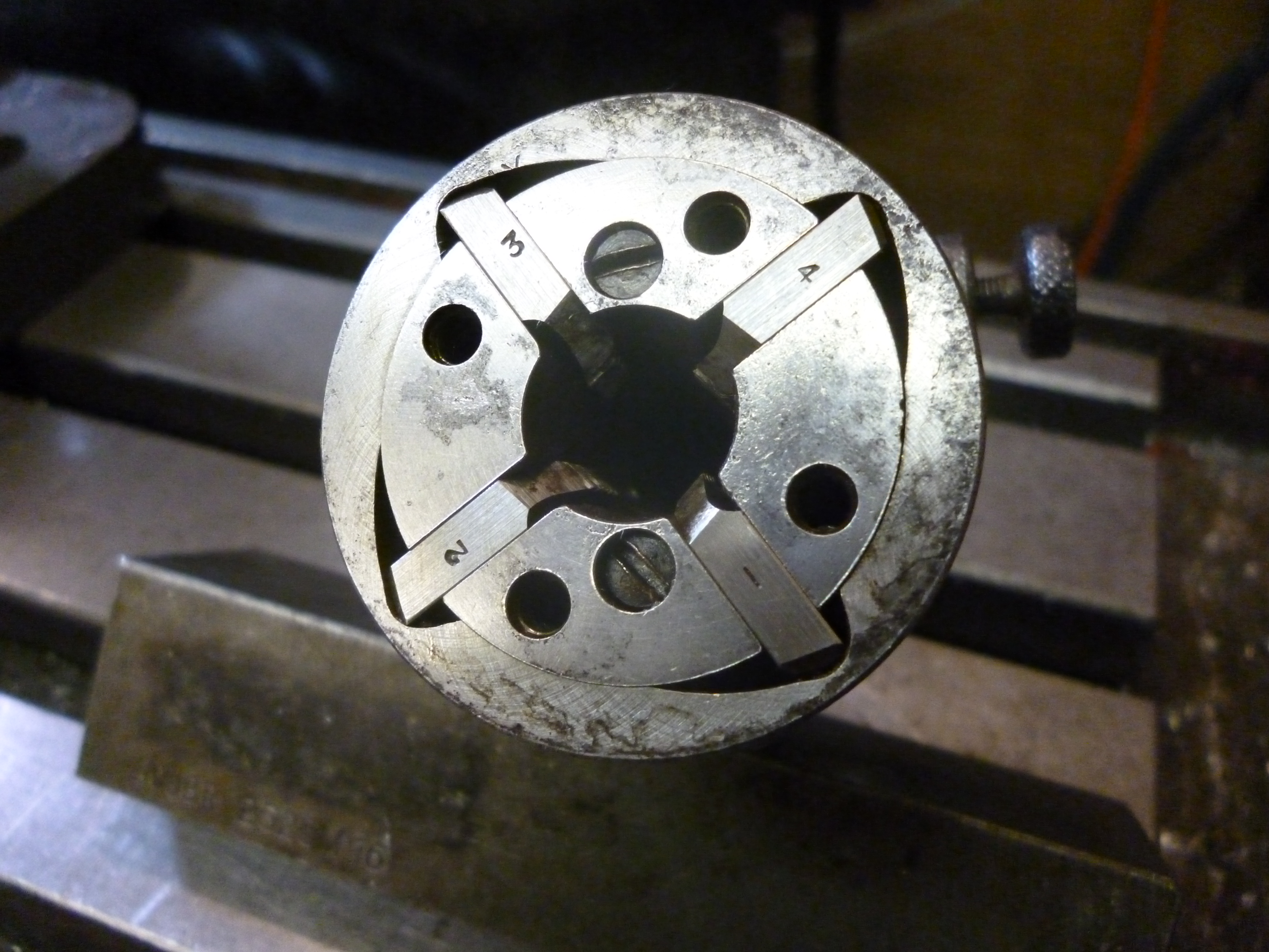
This can hold the usual lathe tools, either a single tool or a quick change tooling system. But, as will be shown, there can be great advantages in using a four way toolholder.
Permutations of the above
Unfortunately not all permutations of the above tool holding systems can necessarily be used together. The first rule is that some means of parting off is usually required. This is, of course, always the last operation. The parting tool will have to be either on the cut off slide or on the cross slide. But on the other hand the width of the cross slide limits how close the capstan tooling can get to the workholding device. On a small lathe designed solely for capstan work there will only be a cutoff slide and no cross-slide. On a small lathe not designed primarily for capstan work the cross-slide is there whether it is wanted or not. Invariably this cannot easily be removed. In this case it might be possible to fit a cut off slide for parting off on the cross slide but the use of the cross slide will be limited because with a cutter near a small workpiece the capstan will crash into it.. On larger lathes a cross slide with a four way tool post only works on a turret lathe where the turret can move far enough back so the tooling on the cross slide can be used efficiently. In the home workshop the most likely arrangement will be an ordinary lathe with the normal cross-slide, with the tail-stock removed and replaced with the capstan. In this case a parting tool of some sort will be mounted on the cross slide. However it will be shown that it is possible to use a four-post tool-post on a lathe with or without a capstan to produce large quantities of small parts.
It is always a good idea to make sure tooling is rock solid and cannot move for any reason. This is even more important when using a capstan to make a large number of parts. If making one part and something goes wrong one part is lost. When hundreds of parts are being made and it is possible for a tool to slip it can only be after many parts have been made that this is discovered and many useless parts will have been made and the material used has been wasted.
A related problem is that of “quality”. By “quality” what is meant here is those little details that make the part look properly finished. One example would be chamfering corners or removing burrs. These sorts of thing can be easy to do whilst the job is being done but cannot easily be done after it has been parted off.
When setting up the system the operations that are essential are obvious. Those that finish the job properly are often more subtle.
Screws used on tooling
It is traditional to use screws with square heads on the tooling used on capstan lathes. In particular screws used to hold pieces of HSS in toolholders or tool held in fourway tool posts. This seems to be simply as a matter of tradition. In practice getting hold of keys for square heads is very difficult. However, much of the tooling that can be bought will be found to use imperial threads. Very often is is not possible or practical to rethread these. The outcome is use cap screws and adjust them with Allen keys.
In industry the fear of tooling slipping and resulting in large numbers of useless parts means that there is a tradition of tightening tooling very hard. One consequence of this is that small screws and nuts used for holding tooling are often spoilt and/or damaged. Any like this should be replaced.
Where screws are tightened too much the ends of the screws can be squashed. It might not be possible to extract them normally. In this case it is often possible to grind the squashed end off.
All cap screws or grub screws should have dog point ends so if they are squashed they will still be extractable.
Possible positions for tooling – Capstan
Movement of the capstan
The capstan will always be limited in how far forwards it can slide. It is also limited in how far back it can go as well. On the capstan shown the maximum movement is about 160mm. It is useful to mark these points on the capstan’s body.

988 – markings on the capstan
The outer marks are the two limits of the capstans movement. The middle mark is the furthest the capstan can be moved back before it starts turning. It might seem, at first sight, that this means a drill of about 80mm in effective length could drill a hole of about 80mm. Needless to say this is completely impossible. On the forward stroke it does appear that one can drill the hole. The problem arises when the tool is retracted. If it is not limited by the stop and is in the farthest forward position as it is drawn back after about 100mm the lock that stops it rotating is released and the capstan starts to rotate. This means that the drill must be clear of the workpiece at this point or the capstan will appear to be stuck. It is stuck because part of the drill is still in the workpiece. This means that, on this capstan, the maximum length a workpiece can be, from its right hand end is about 100mm.
Fitting tooling to the capstan
The axis of the capstan is usually tilted. (A turret lathe, on the other hand, usually has a turret whose axis is vertical.) The capstan has five or six holes round its circumference which, when any of them is selected is parallel to the bed of the lathe. The inside of these holes are always parallel. Common sizes would be 5/8 and 3/4 inch for smaller capstans and 1 inch or more for larger ones (or metric equivalents).
It is highly desirable that all tooling is fitted to the capstan so it cannot move in or out or rotate in the capstan socket.
When it is necessary to hold tooling with a taper it is possible to buy tapered sockets with parallel shanks. Very often these are too long but they can be ground to make them shorter. However these are not made so as to fit the tang of the taper. This means that they can rotate. To prevent this the taper has to be hammered home tightly with a soft headed mallet. In general the way the tooling works a slight rotation is not catastrophic.
1089 tapered socket 1
Fig – tapered socket 1089
The rigidity of any tooling is always limited by the diameter of this shank. In general, it is always desirable that the distance, as the metal goes, from the capstan to the cutting edge is a short as possible.
In this case just less than half the sockets fits into the capstan. The sleeve is ground in half and just the wide end is used. If this is done the taper that goes into the socket will also need to be shortened.

1095 sleeve ground in half
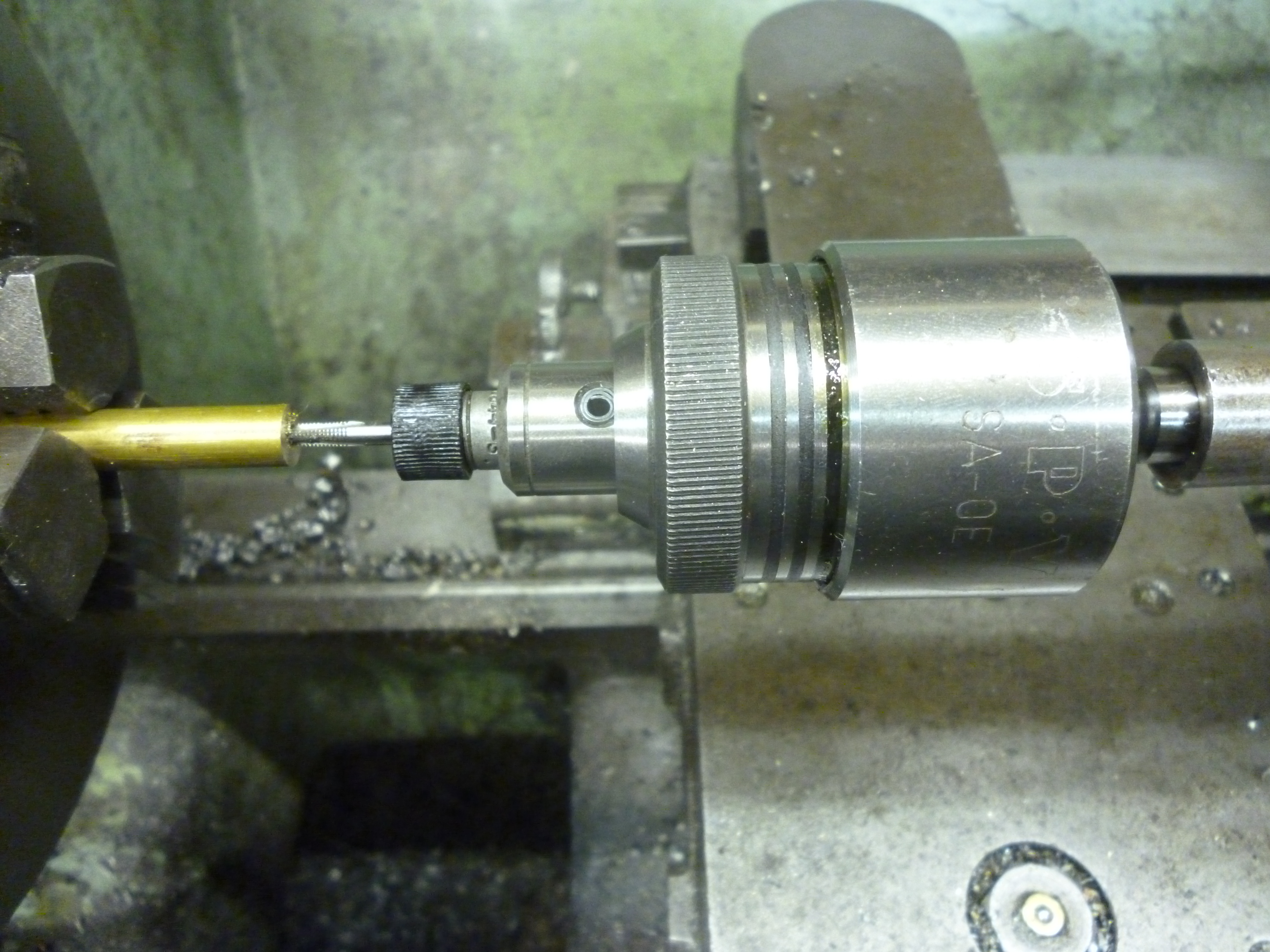
Stops on the capstan
Simple capstans might not have any stops. In practice this severely limits the efficiency of the system. A better method is to have a rotating stop – even if this has to be rotated manually. This can be done by fitting a stop on each tool that hits a fixed point on the cross-slide (which would usually be locked in position on the lathes bed). The ideal system is a set of stops, one for each tool. This is rotated automatically as the capstan rotates.
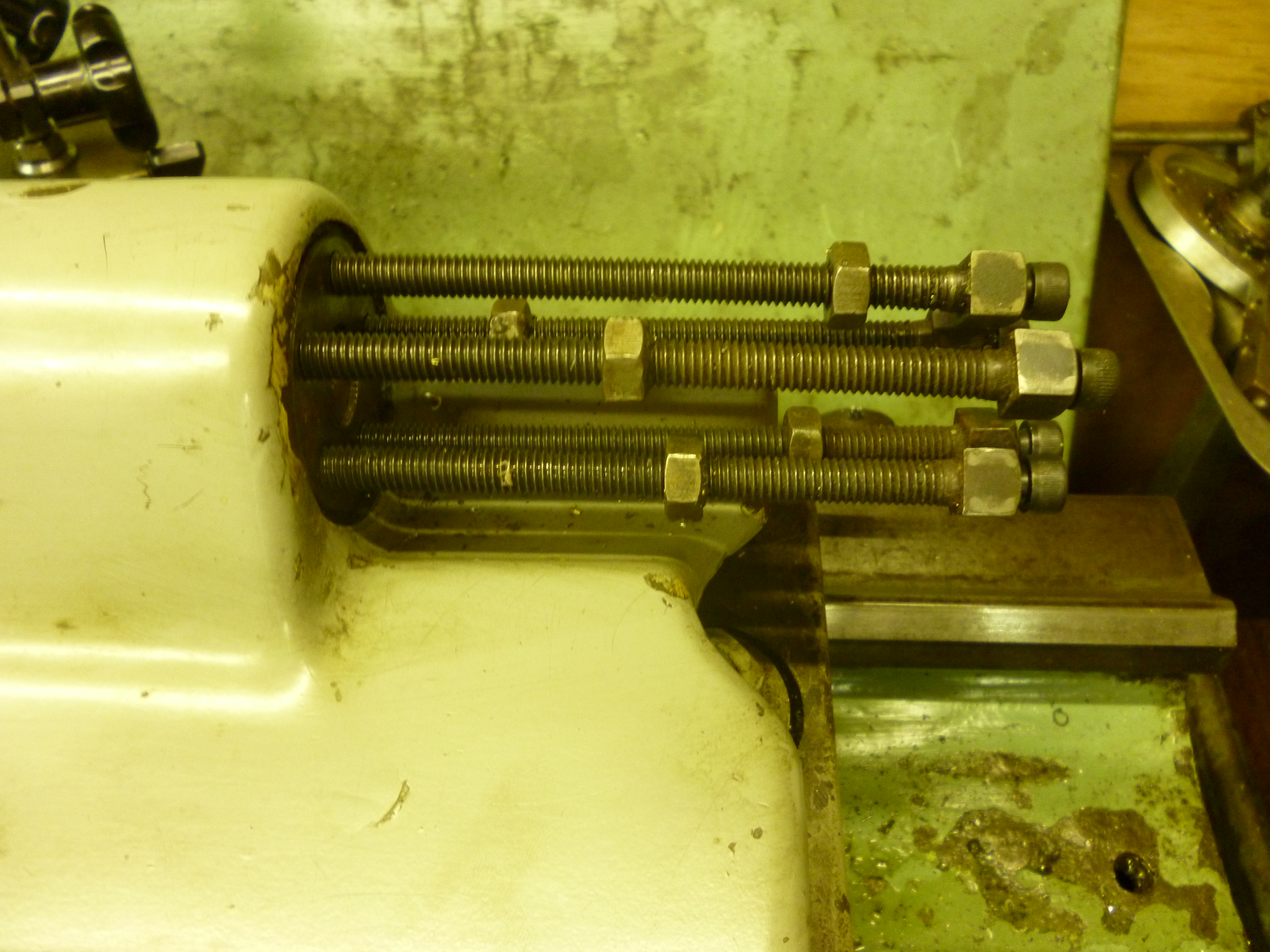
Stops on the capstan 990
In the photo above the screw at the bottom is the stop for the current position of the capstan. It will be noticed that the screws have square heads. Square heads are almost universal on capstan tooling. In this case, the screws have been fitted with cap screws so they can be adjusted with Allen keys. Each screw has a locking nut which should always be used if the stop is being used. Stops that are not being used should set to allow the maximum distance of travel and then locked.
Alignment of the capstan
On most, smaller, general purpose lathes the capstan is an attachment that would be used as needed. When fitted, as it slides it does not slide on the bed of the lathe but on a bed of its own. This means the capstan does not automatically line up perfectly when it is installed. It is up to the user to see that it is aligned properly. The capstan only moves laterally by a very small amount. It is very important that the axis of the spindle in the headstock is aligned in the horizontal plane with the axis of each of the sockets on the capstan. Of course it is necessary that the axis is horizontal but the that is built into the fitting.
This can be done by fitting a center to the headstock and a center in the capstan. A test bar is fitted between these. A dti is used to check that the parallel part of the test bar is parallel to the bed of the lathe.
Fig – testing the capstan is lined up with the headstock 907
Capstan tooling
The tooling in the capstan can do three basic types of operation. In the first the tool lies on the axis of the workpiece. This includes center drilling, drilling, counterboring, reaming and cutting internal and external threads. The second type is the traditional turning. In this the cutting tool sits on one side of the workpiece. In both of these types the cutting edge only moves from right to left. The third type of tooling that fits the capstan is “swing” tooling. In this the tooling fits in the capstan. However, in operation, it moves from right to left parallel to the axis of the lathe, without touching the workpiece, and then moves in or out to cut.

1094 coaxial operation
Fig – cutting where the cutter is coaxial with the spindle
In this case the forces acting on the cutter are symmetrical.
In the second group the cutter is to the side of the workpiece, this includes turning.

1095 asymetrical operation
Fig cutting where the cutter is not coaxial with the spindle 1095
In this group the cutting operation is not usually symmetrical.
In all these cases the tool starts off to the right of the workpiece and moves to the left until it hits the stop for this position on the capstan.
One of the standard tricks that can be used to get more done in any capstan position is that, very often, any of the first group of operations can be combined with one or more of the second group, ie, turning operations .
1096 drilling and turning together
fig drilling and turning at the same time
For many jobs a very common sequence of operations would be to center drill, drill and tap a rod. In this case one position would have a center drill in it. The next position would be a drill for the size of tap needed. The next would be the tap. During any of these it would also be possible to turn the outside of the workpiece at the same time.
The third type of cutter is the swing type. This has an arm that has a cutting edge that can be move in or out.
The start of the cycle
The nature of the workpiece
When using a capstan there are two basic types of workpiece. Firstly, the workpiece is the end of a long bar. This is fed from the back of the headstock through the bore of the spindle. In this case the workpiece has to be fed out to a particular point. This uses a workstop in the first capstan position. The other option is that the workpiece is already in the form of a short length. It might even have been made from a long bar as has just been described. In this case it has to be manually fed into the chuck from the front. It has to be fed in by a certain amount. This can be done using a stop inside the chuck.
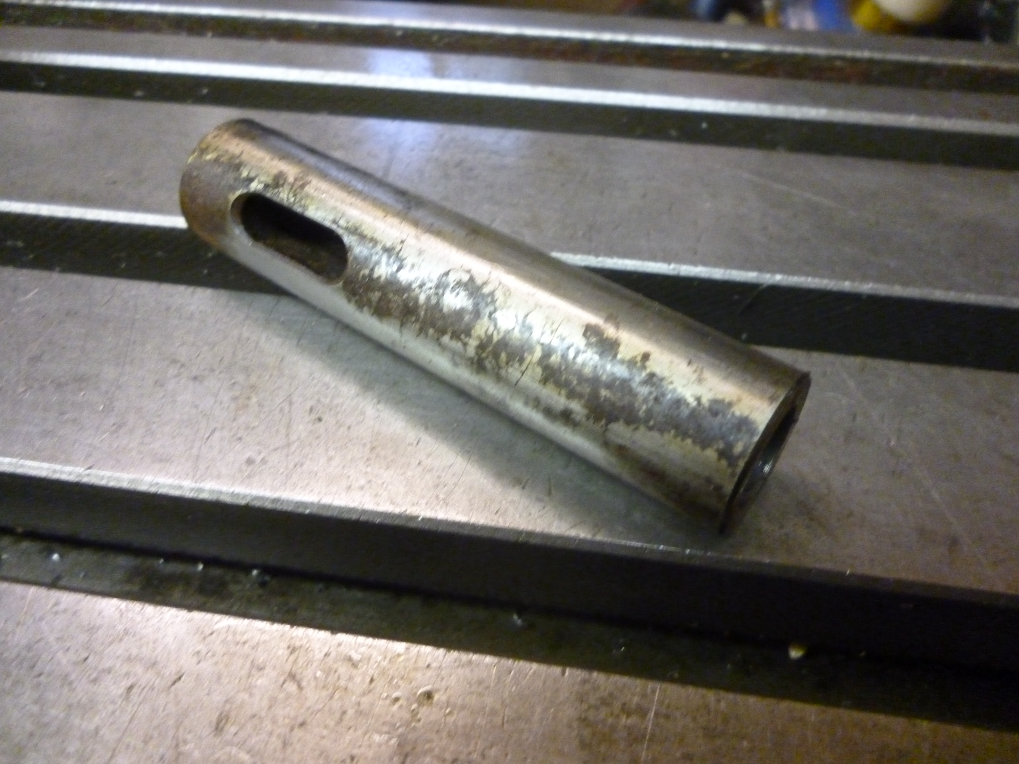
The workstop
If there is no automatic feed from behind the headstock, then the feedstock has to be pulled out of the collet manually. The collet is tightened so it can move but not unless it is pushed. The workstop is moved forwards and pushes the feed stock into the collet until the workstop itself hits its own stop in the capstan. The chuck is then tightened.
982 adjustable work stop
When using a bar as feedstock this has to be the first step of every cycle. At the start of a cycle it is essential that the end of the feedstock is in a definite position. This is the “feed to stop” operation. This will define the position of the right hand end of the work piece. In this step the workpiece is not rotating.
Fig – Setting the end of the workpiece 908
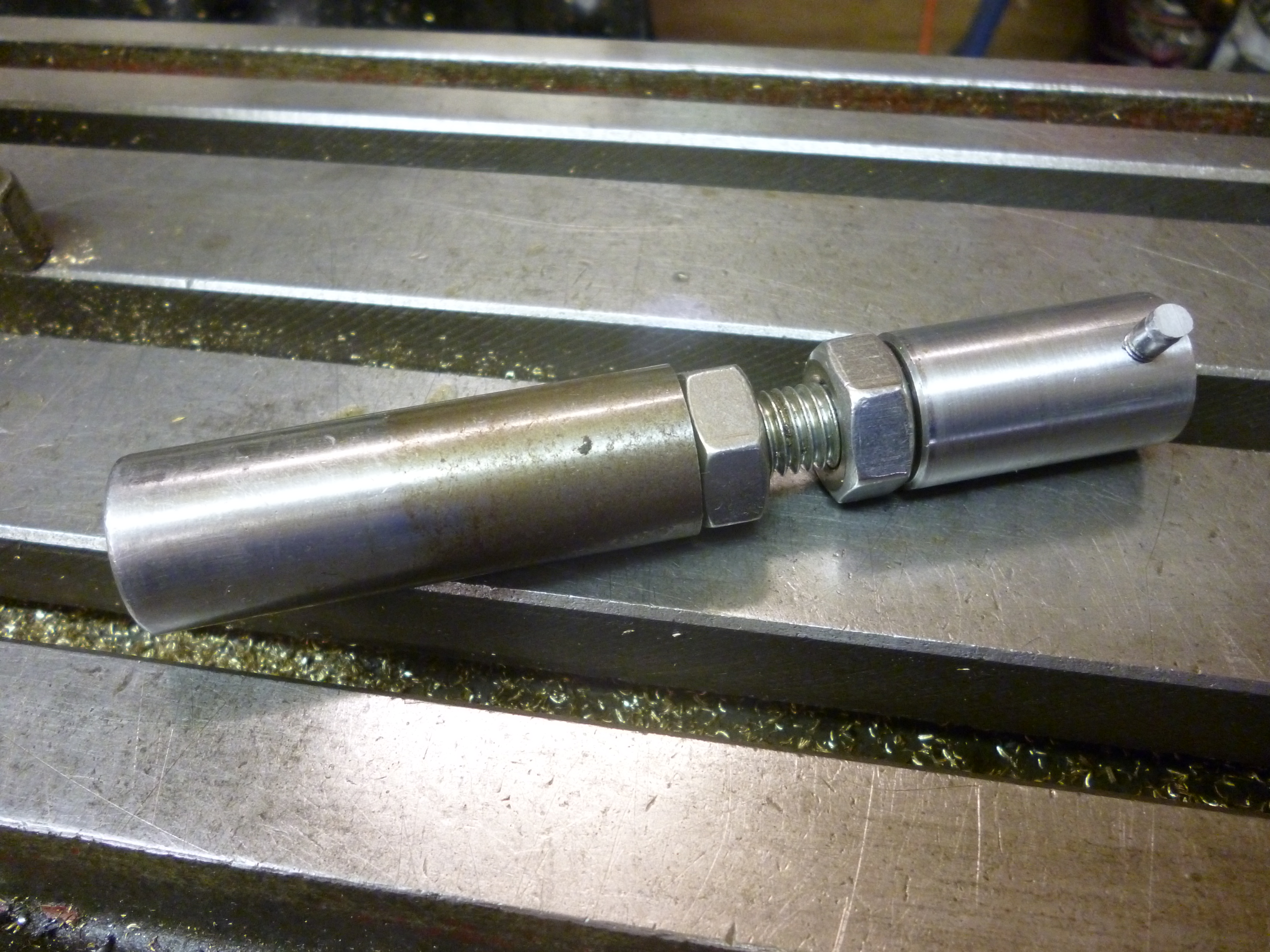
The workstop can be fed to any position but will it stop according to the setting of its own stop in the capstan attachment. Even so it is useful if the stop is adjustable. It is quite easy to make a workstop that will function at almost any point in the capstans range. This is done by making the stop with the stop bit on a thread that can be screwed in or out of the main shank. In practice this will often be set towards the start of the capstan’s range because any tool behind this point will not be able to reach the workpiece. More on this later.
Notice that there is a lock nut to ensure the workstop is always the same length. It also makes the whole assembly more rigid. A screw mechanism is used because, if a sliding mechanism with a screw is used then as the end of the workstop is continually being hit by the bar it can slowly move. If it moved suddenly it might not be so bad. The problem is it might move very slowly. This means that only after many parts have been made is the movement noticed.
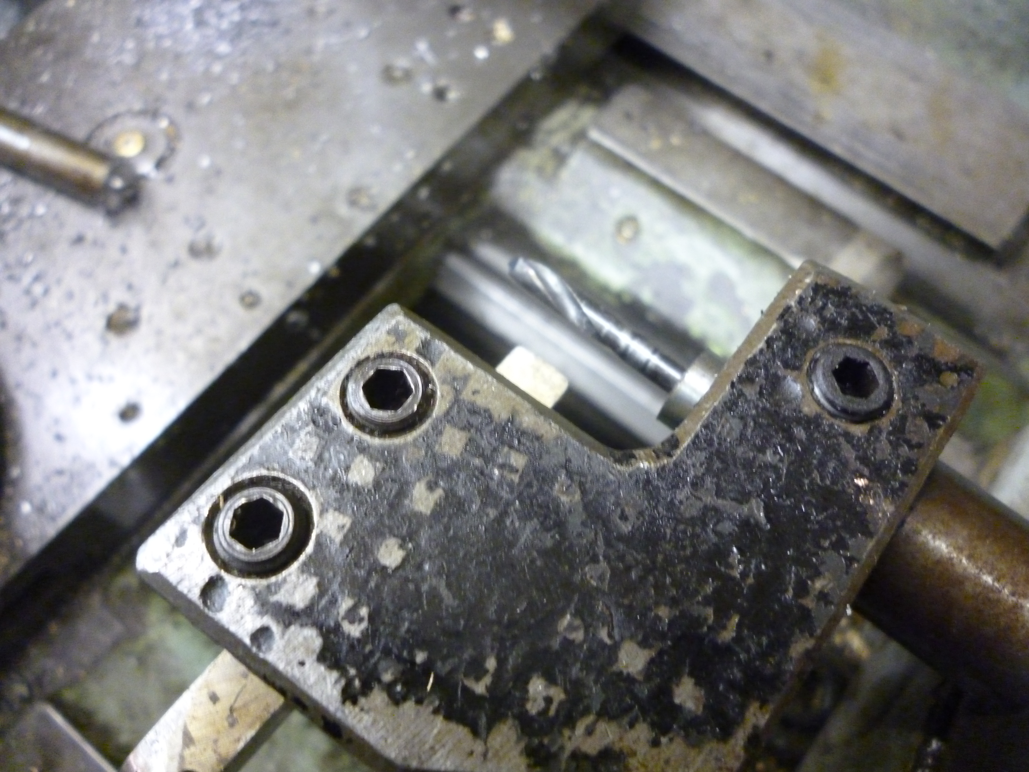
Work stop with center drill
It is often necessary to center drill the workpiece. The center drill could be held in a collet chuck in the second position. But, at the same time we want to get as much done for each capstan position as possible.
This can be done by being able to fit the workstop with a center drill. Of course if it was fitted all the time the work stop would not work properly. The center drill has to be “ahead”, i.e, to the left of the workstop when either of these has hit the stop. The way to do this is to be able to fit a holder with the center drill in it over the end of the workstop. One easy way of doing this is to make a cap that fits on the end of the workstop.
The center drill has to be a good fit so that it is concentric with the axis of the headstock and it must be made so it cannot rotate. One way to do this is to mill a slot in the cap. The workstop has a pin in its side. The slot on the cap slides on the this pin. This stops it from being able to rotate.

981 center drill for use on work stop
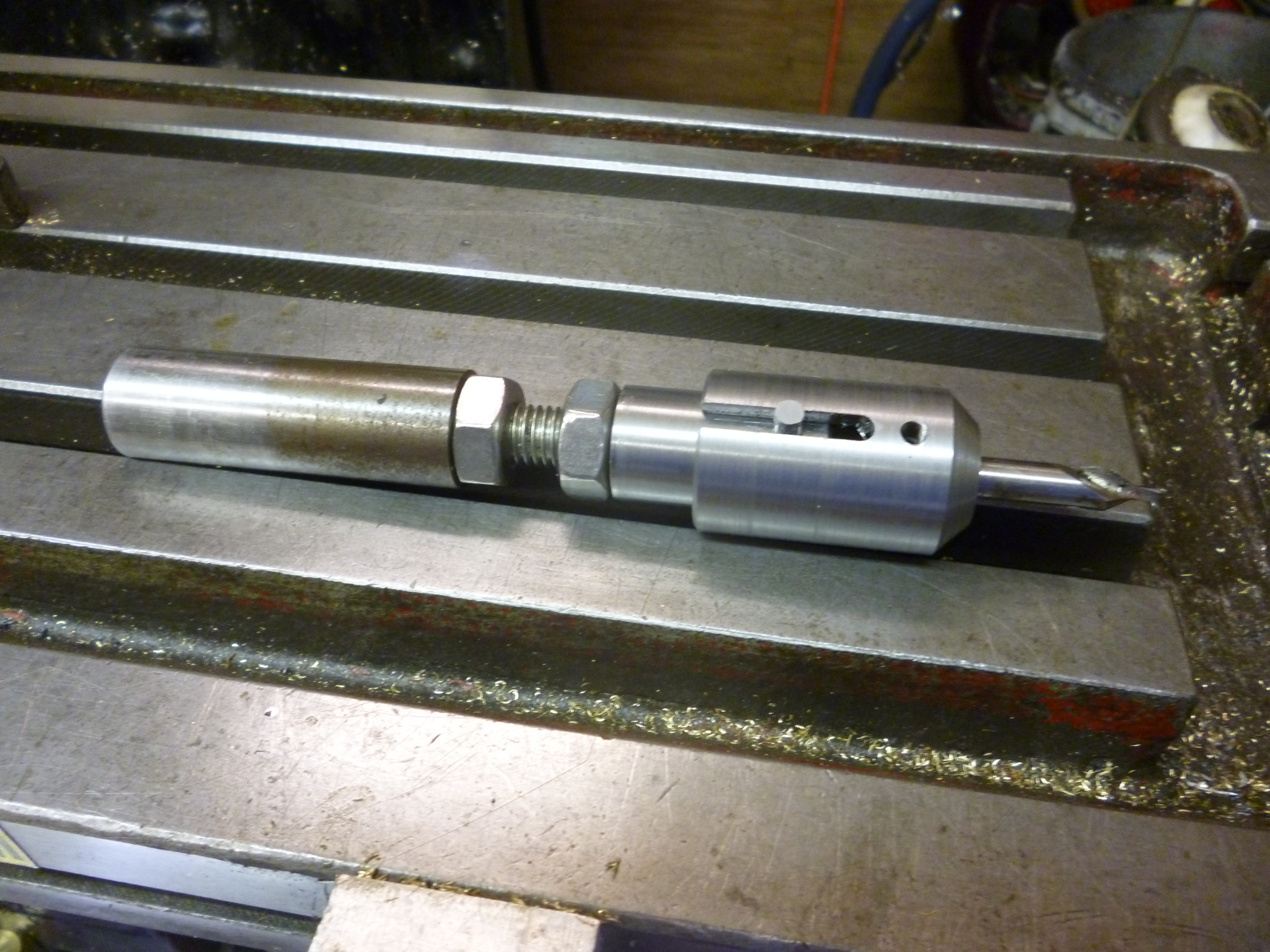
983 adjustable work stop fitted with center drill
This works because center drilling is about the only operation that can be done properly and with the required accuracy without having its “own” stop on the capstan.
Center drills usually have a drill on both ends. Here the center drill has had the cutting part that is not being used ground off. It then has a groove ground in it so the grub screw holding it can really stop it moving longitudinally or rotationally. This is because distance is always at a premium. This is because, firstly space is limited, and, secondly, shorter is always more rigid.
Boring
On a workpiece made from a bar the diameter is limited and most holes can be made by drilling and reaming.
Usually when boring on the lathe many cuts are taken till the right size is achieved. Even then it is always worth doing two or three passes to get the best finish and most accurate size. On the capstan lathe the idea of having to take many passes and adjusting the boring tool each time is not attractive.
Boring can be done with something like a small boring head fitted to the capstan. This would probably only be done if it was not possible to get a reamer of the required size. Otherwise a drill would be used to drill a hole so that only one pass at one setting would be required with a boring tool.
Reaming
Reaming is usually done with machine reamers. These can have parallel shanks or tapered shanks. These do not have a long lead in like hand reamers. The cutting edge is the end of the flute that is ground at 45 degrees. Hand reamers are usually unsuitable because they need to be able to go beyond the end of the hole being reamed.
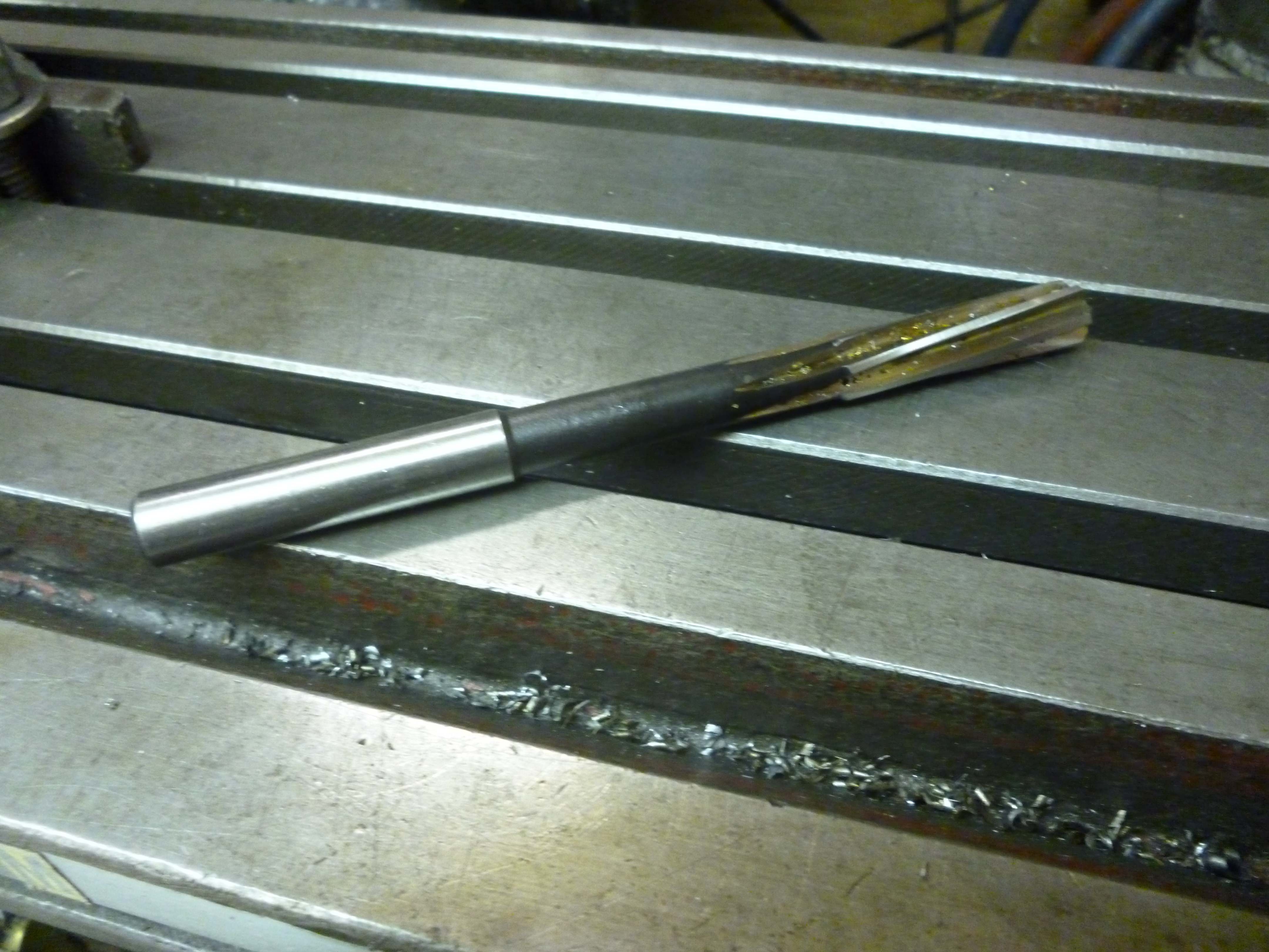
3029x machine reamer
Fig – machine reamer
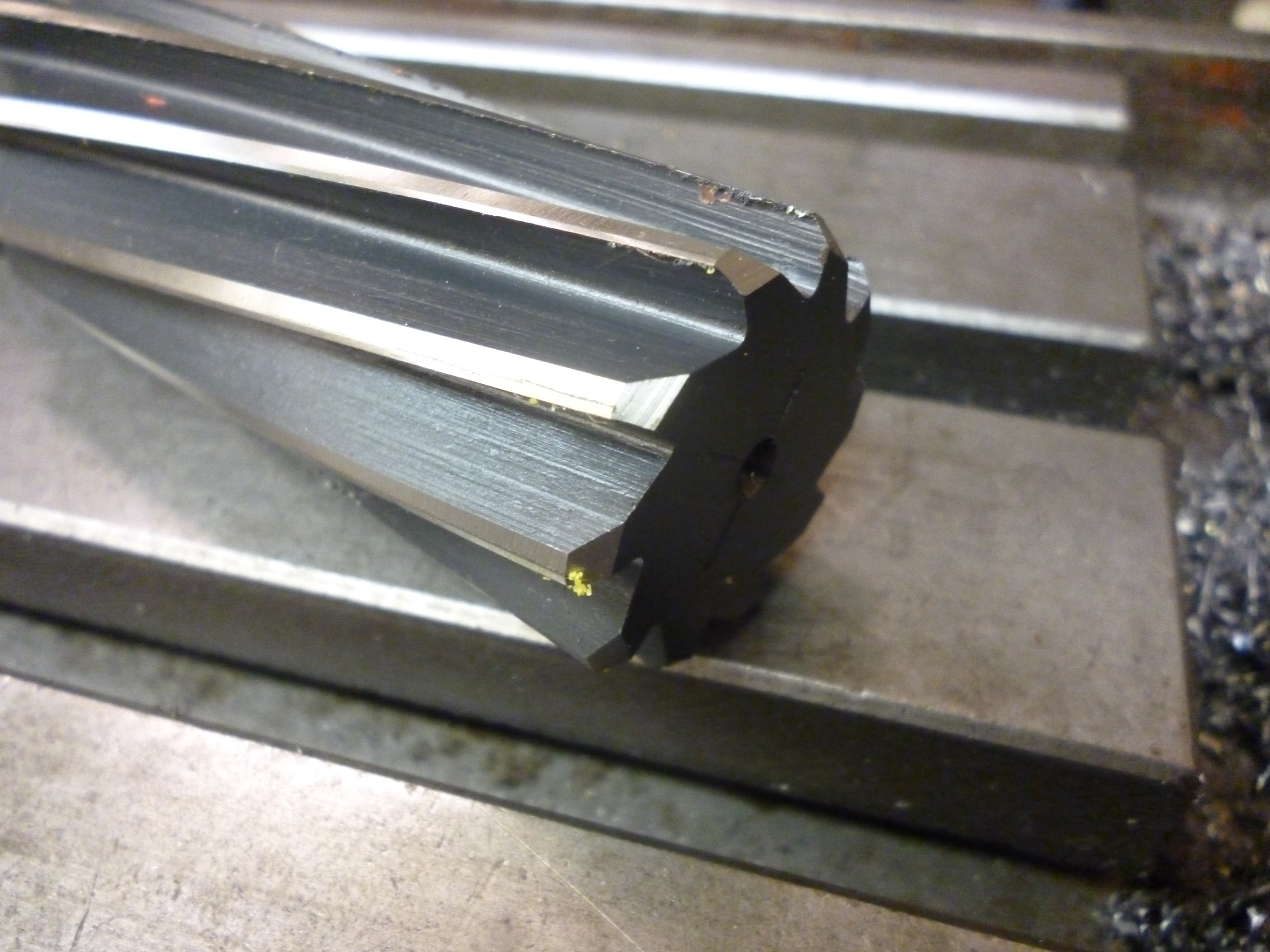
3030x machine reamer – cutting edges
Fig – cutting edge of a machine reamer 919
These are usually run straight into the workpiece.
It is always necessary to use lots of cutting fluid during reaming. Usually reaming is done at a lower speed than drilling the same size hole, e.g., half.
For successful reaming it is essential that is enough metal for the reamer to be able to cut properly at the same time it is important that the reamer does not have to cut too much. This extra is known as the allowance.
Allowances
****
When the reaming is complete the reamer should be withdrawn whilst the workpiece is still rotating.
Holding reamers
Reamers can be held in a collet chuck.
Unless the axis of the workpiece and the reamer are perfectly aligned the hole will not be truly round and might be slightly oversized.
Ideally, reaming is done with a floating tool holder. This holds the reamer so it is parallel to the hole that is to be reamed but is free to move very slightly either vertically or horizontally or both. As can be seen from the photo these holders can be very simple and easy to make. A test piece is used to set the reamer so it is aligned. The bolts are then tightened so it is fixed in this position.
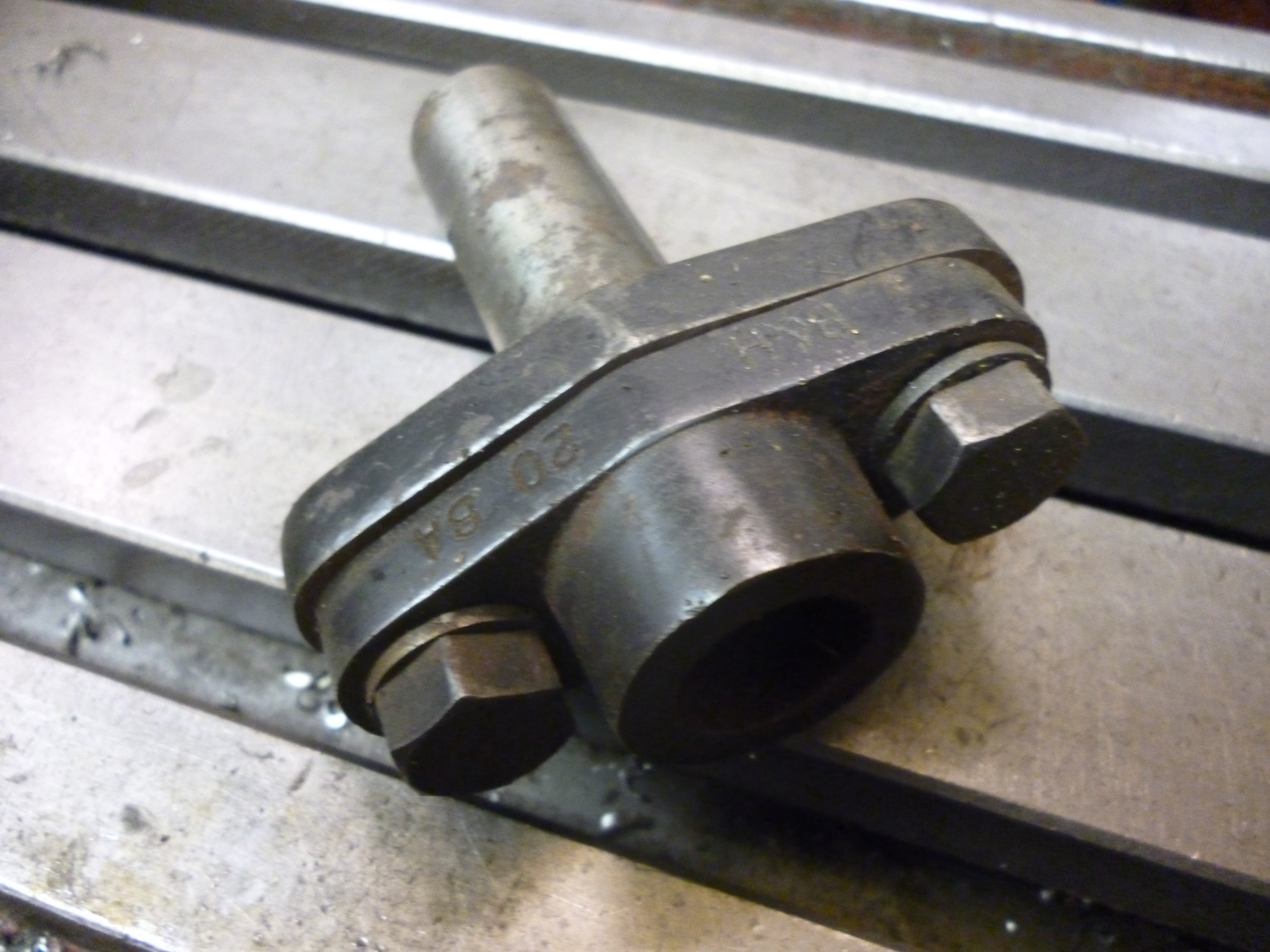
floating reamer holder 921
If a reamer is held in a holder like this it will only be right with the holder rotated to one particular position on the capstan.
More exotic floating reamer holders use roller bearings that enable the two parts to slide relative to each other.
Fig the inside of a floating reamer holder
Threading
Internal threads – use of taps and tapping heads
Internal threads can be cut using ordinary taps.
In all cases, except when tapping cast iron, some sort of cutting fluid or cutting compound should be used.
If the job requires a tapped hole then this will require at least three operations. Firstly to center drill the hole, secondly to drill the hole and thirdly to tap the hole.
In most cases, the tap will be going into a blind hole in the end of a bar. If a first or second tap is used the thread will not reach anywhere near the bottom of the hole. In some cases it might be possible to make the hole deeper so what is threaded will be long enough. Alternatively a second position could be used to hold a third tap. There are taps with spiral cutting edges that tap very near to their end but do not need first or second taps.
fig a spiral tap
If the lathe is being driven by the motor during a tapping operation and the tap is small, as if often the case, when the tap cannot turn, it is likely that the tap will break. One might hope that the user could see this and stop the motor. But, especially with small taps, the user will not be quick enough.
Whenever a tap is used as the workpiece rotates the tap is drawn into the workpiece. There always has to be some means of stopping it. The usual stop on the capstan is useless. If this stop is hit then the outcome has to be wrong – the tap will be broken or the thread will be spoilt. There are several solutions to this.
Tapping – turning the chuck by hand
Instead of letting the motor drive the workpiece round the motor is turned off or disengaged and the headstock is rotated by hand. If the user is turning the spindle by hand when the tap hits the end of the hole it can be felt. But with small taps it is very easy to turn a large chuck with enough force to break the tap. Once the tap has finished tapping the spindle has to be reversed either by the motor or by hand to remove the tap from the workpiece. Ironically, it is not only small taps where the chuck has to be turned by hand it is also the largest taps. This is because where the lathe is not powerful enough to cut the thread it can often be cut if after half a turn of cutting the chuck is reversed. This is what is often done when tapping by hand. It works because when it is reversed it breaks off the metal being cut and make the next cutting action move less metal.
Tap holders that disengages the drive to the tap
Another solution is to make the tap holder so that when the tap have been pulled out a certain amount it disengages and the tap rotates freely. Then the drive has to be stopped. In the simplest case the piece that holds the tap is knurled. The user stops the drive, holds the knurl, and puts the drive into reverse till the tap has come out of the workpiece.
Tap holder with torque control
Another solution is to use a special tap holder that can be adjusted so that the maximum torque that can be applied to the tap is limited. When the tap hits the end of the hole the tap simply rotates with the workpiece.

tapping head 2 – 963
Fig tapping head with torque control – tap not retracted 963
The user has to make the tap move forward until it catches. Once it has started threading the part holding the tap comes out of the tapping head. When the tap gets stuck the tap simply rotates with the workpiece.
tapping head 1 – 962
Fig 34 tapping head with tap drawn out 962
The hole has been tapped and the tap is turning, the user has to stop the spindle and put it in reverse. In reverse the tap holder is locked and will not rotate. As the lathe runs in reverse it feeds the tap out. The user can then wind the capstan right back.
Wherever center drilling, drilling or tapping takes place it is also possible to have other operations happening “off center”. For example, a cutter that would reduce the diameter of the bar.
External Threading – use of dies and dieheads
A very common operation on a capstan lathe is cutting an external thread. Usually these threads are relatively short. Any threading operation can only be done if the part of the workpiece to be threaded is already of the right size of outside diameter.
Secondly, if a die is being used, the chances of the thread being straight will be better if start of the part to be threaded is chamfered to take the die. This also makes for a thread that is easier to screw nuts on and gets rid of any sharp edges.
The die must be mounted so that is face is always at right angles to the axis of the lathe.
Fig die holder
When the cutting starts the die must not rotate. At a certain point the cutting will be finished and any cutting must stop. If the workpiece is being rotated by hand then this stops. If the workpiece is being driven round then it is possible to make the die holder so that at a certain point the die becomes free to rotate.
When a die is split it will be found to have three dimples on its edge. The middle one coincides with the split. This is merely to stop the die from rotating. In this state it will cut oversize. The two other screws should be tightened till the die cuts the right size. At this point the middle screw should be tightened.
When the die has finished cutting, the lathe can be put in reverse to withdraw the die.
When setting the capstan up always test that the thread being cut actually fits the nuts that are going to be used on it before cutting lots of them. Once this has been set correctly at the beginning it is safe to assume it will stay correct. It is not necessary to test every thread individually.
Use of dieheads
In industry, external threads are cut by using a diehead. The most common examples of these are the “Coventry” dieheads made Alfred Herbert. Though very similar ones were made by other makers. The most common Alfred Herbert style is called “C.H.”.
951 Coventry type diehead
The size of a diehead is the diameter of the largest rod that will pass through it.
Size size of shank outside diameter smallest thread
1 /4 5/8 1 5/8 12BA
5/16 5/8 1 ¾ 10BA
1/2 1 2 ½ 6BA
This size is nominal, often, the actual size that can be machined can be significantly larger. Since the shank is hollow it is not possible to turn it down to a smaller size as it is possible with capstan tooling which has a solid shank.
A diehead has 4 cutting parts, i.e., dies that are fixed at the right distance apart to cut the thread. Any set of dies is made only to fit a particular size of diehead.
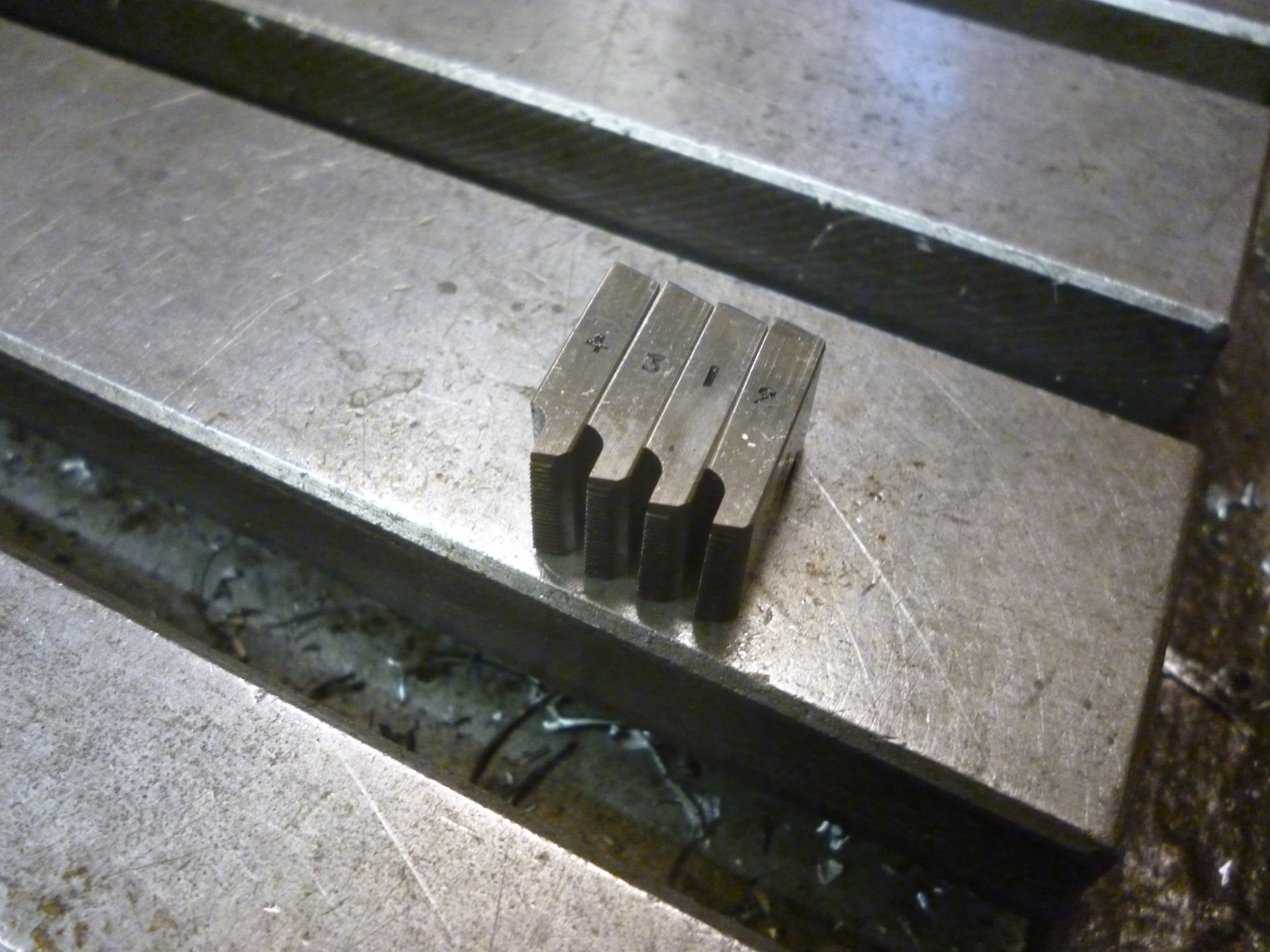
set of four dies – 961
The numbers on the sides of the dies are use to fit the dies into the diehead in the right order.
The default for Herbert dies is that they are for the Whitworth tooth form. In this case they are simply marked with the diameter and the teeth per inch. BA threads are marked with the number and then “BA”.
This can be seen on the face of each die.
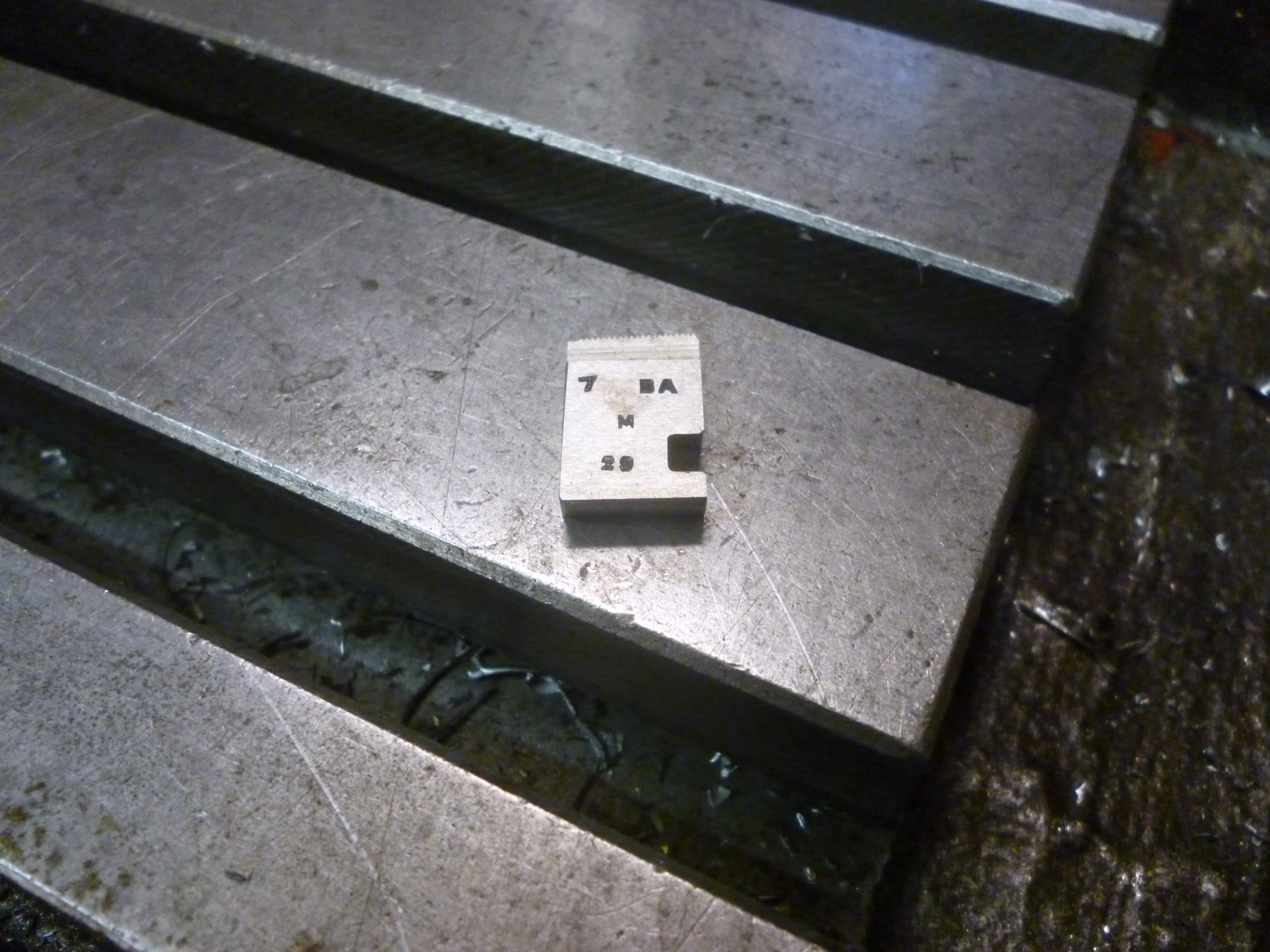
the front face of a die – 955
The next line is the type. This is a code for the type of material these dies are designed to cut.
S mild steel
A5 stainless steel
M cast iron, bronze
AM high tensile steel
M steel
AM5 nickel chrome steels
B brass
4as aluminium, free cutting steel
The bottom number on the die is used when grinding the dies to sharpen them using the special jig that is necessary.
A different set of dies will be needed for each size of thread that can be made with a particular diehead. A set of dies can only cut teeth the size of the teeth on the dies and can only cut to one diameter that is determined by the geometry of the dies.
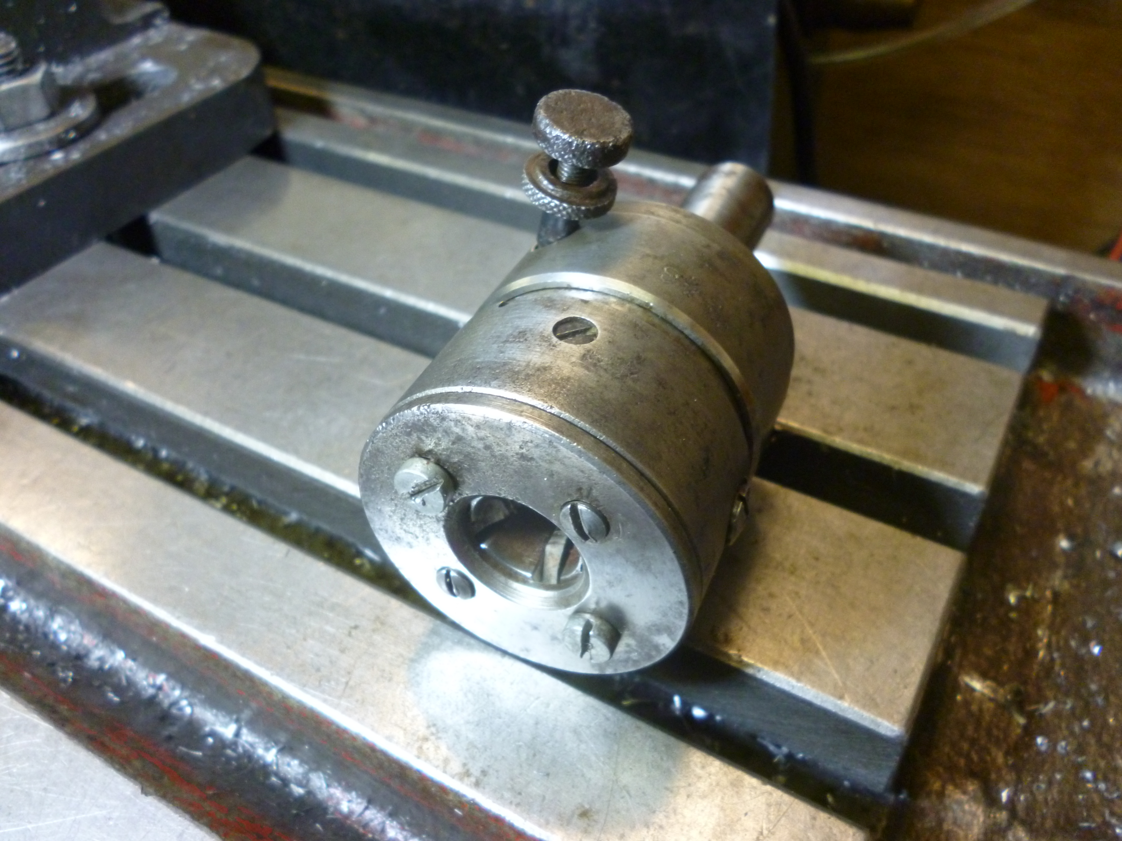
The front of the diehead has a plate on it that holds the dies in place. This can be removed to change the dies.
953 dies in the open position 2
fig – diehead with front plate removed – dies in open position 954
- dies in the closed position – 952
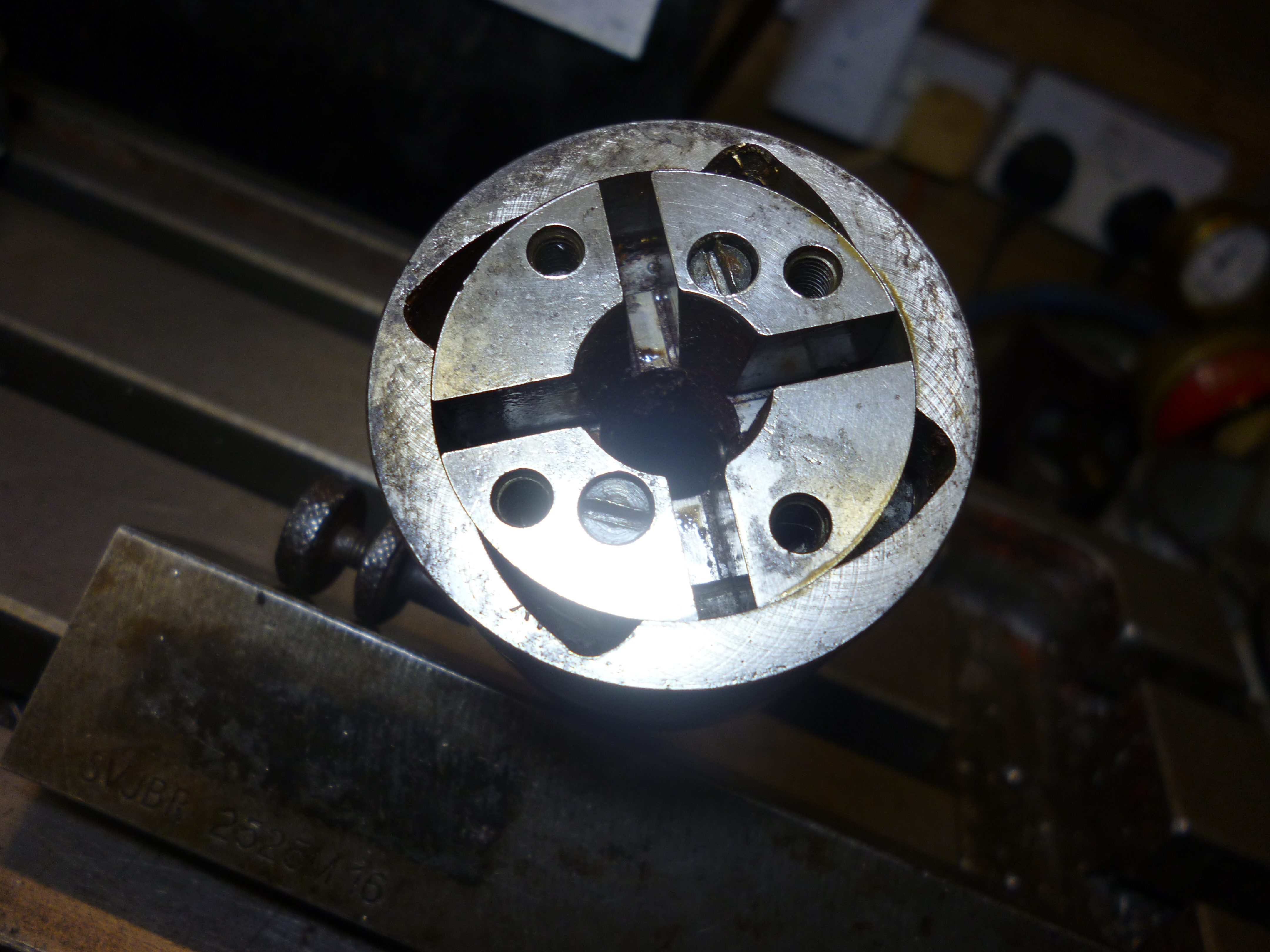 Fig – diehead with front plate removed – dies in closed position 960
The dies fit in a part that is shaped so that if it is rotated it allows the dies to move outwards. This is known as the external scroll.
If the dies are removed it will be seen that behind them there is a part known as the internal scroll. This works like the scroll on a three jaw chuck. As it rotates it moves the dies in or out. The scrolls on this fit into the slots on the dies. As this rotates the dies move in or out.
At the start of threading the dies are in the “in” position.
Fig diehead with dies removed – open position

scroll in the closed position – 960
Fig – diehead with dies removed – closed position 960
When fitting the dies it does not matter which slot the first die is fitting in. All of the slots are mechanically identical. But it is vital that the slots are filled in sequentially and the right way round. Looking at the diehead from the front, the dies must be filled in, in the order 1, 2 ,3 and then 4 in the clockwise direction.

953
Fig – showing order the dies are filled in for a right handed thread
A diehead can be used to cut left handed or right handed threads. But a different set of dies is required for left handed to right handed ones. When left hand dies are used they are fitted in clockwise order. When cutting a left handed thread the workpiece has to turn in the reverse direction.
In use the shaft of the diehead must be mounted so it cannot rotate but can be pulled forward by the workpiece. This means that it cannot be mounted in a taper held in a tailstock – it will probably get pulled out.
The diehead is pushed forwards manually until it starts cutting. After this it must be free so that the diehead will be pulled forward by the thread it has already cut.
However there has to be a point where a stop is hit. The diehead cannot move forwards any more. But the front part of the diehead is pulled away from the back. When this happens a detent is tripped and the dies spring away for the workpiece. The diehead can then be retracted, manually, without have to “unscrew” the workpiece.
When the diehead has been tripped the dies are in the open position. In order for it to cut the next time round is has to be closed by using the closing handle. This has to be done by the operator. On turret lathes it is usually arranged that this is done automatically.
fig handle for resetting the diehead
A diehead can cut a thread till it has gone all the way through the diehead. At the end of the diehead is usually a solid part of the capstan which limits the length of thread that can be cut.
A diehead cannot cut a perfect thread all the way up to a shoulder. If this is a problem then the half formed thread must be cut away using some sort of swing tool. As the dies are ground to resharpen them the distance between the front edge of dies and the front of the diehead will increase. This needs to be checked when buying old reground dies.
Adjusting the size of the thread
The diehead with a set of dies is designed so it can cut a thread that is just too big down to one that is just to small. This is adjusted by means the the knob shown in the photo. Notice the essential locking nut. There is also a small scale for calibrating the adjustment.

951 coventry type diehead showing adjusting screw
fig screw for adjusting the diameter of the thread
When setting this up, the thread that is formed should be too large. In most cases it can be tested using a commercially made nut. The same thread can then be recut after making a small adjustment until the nut fits. Then the knob is locked.
Rough and finishing cutting
The two smallest sizes of the CH type heads only cut to one size once set up and adjusted. Sizes larger than these have an extra handle. This can be used so that the one diehead can be used to cut two slightly different sizes of one size of thread. One is for the first or rough cut. The other is for the final, fine cut.
fig knob for switching between rough and finishing threads
In this case the diehead would be in one position in the capstan. It would be fed forward for the the first cut. It would then be retracted. The small handle would be switched to “fine” and it would be fed forward again. It is, of course, essential that when the capstan is withdrawn it does not go past the point of no return.
Rotary broach
Odd shapes can be cut in the end of a workpiece by means of a broach. An example of this are the hex sockets found on cap screws. A hole is drill to remove as much material as possible. The broach is then forced against the workpiece as it rotates.
Fig rotary broach
The rotary broach is free to rotate but it is also held at a very slight angle to the axis of the lathe.
Fig rotary broach in holder
Knurling
Knurling is done by pressing two hardened wheels against the workpiece. The knurling wheels are covered in a pattern of projecting ridges. These form indentation in the workpiece. If a material is soft enough to be knurled then a good knurl can always be produced if the pressure is hard enough.
Knurling is slightly different from most other capstan operation in that it is seldom possible to cut a suitable knurl simply by driving the knurling tool onto the workpieces. In practice the knurls have to be placed whilst loose over the spot to be knurled. The knurls then have to be tightened by the user. When the knurling is complete the knurls are loosened and the knurling tool retracted.
Knurling wheels are only about 6mm wide. A longer knurl has to be done by moving the knurling tool left/right several times.
Straight knurls are done with straight wheels. Diamond knurls are done by using crossed knurls.

936 – box for knurling
Most knurls produced are on or near the end of the workpiece. Very often, the knurl will be the widest part of the workpiece. So the knurl will often have to be at the left hand end of the workpiece. This particular knurling tool is made so the knurl produced can be up to about 75mm from the end of the workpiece (unless the workpiece will fit into the shank on this tool, in which case it might even be more).
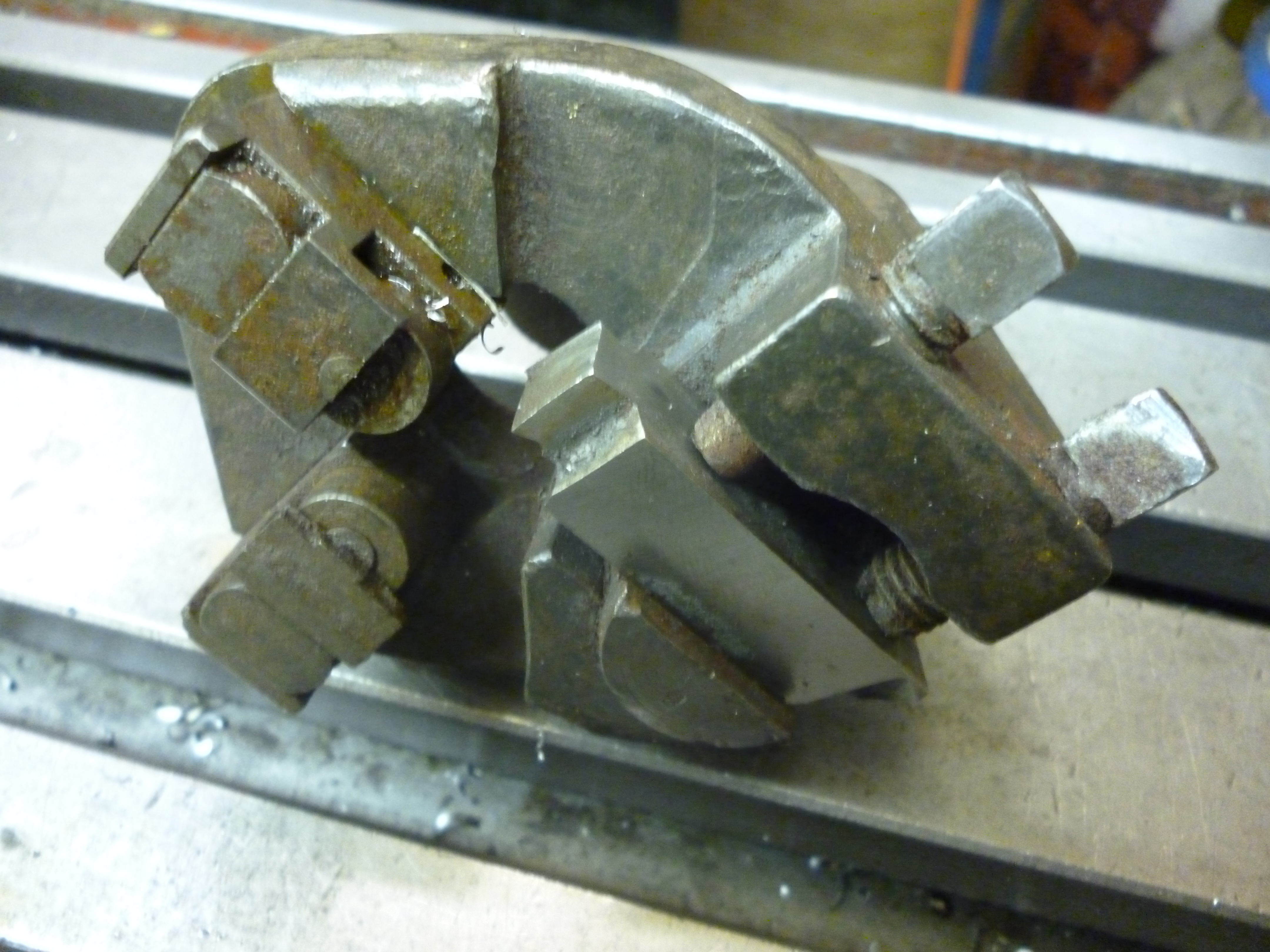
Capstan operations – asymmetrical – “Turning”
Suppose the workpiece has to have its diameter reduced by a small amount so that it can be cut in one pass. The general shape of the tool has to be as shown.

1086 knee 1
Fig – tool for cutting a workpiece
The cutting edge is just as it would be when turning on an ordinary lathe. On an ordinary lathe the cutting tool can usually cut either going left to right or left to right or in and out. On a capstan, on this type of holder, the cutter only cuts from right to left. What actually matters is the rake and clearance angles at the edge where it is cutting. It is easier to set these if the cutting edge at the nominal top surface of the cutter is at right angle to a tangent on the surface of the workpiece.
Ideally this top surface is horizontal as it would be on an ordinary lathe. But with a capstan it is not uncommon to have more than one cutter at a time. This means that one or more might be at other angles. It can be useful for the cutter to be up side down. In this case the swarf falls away naturally also the cutter is on far side from the top side which might leave space for other tooling.
The cutting edge can touch the surface of the workpiece at any angle but is every case the clearance angle and the rake angles have to be computed relative to the radius at the point where the cutting edge touches the workpiece.
Fig – clearance and rake angles
The cutting edge is in the horizontal plane. The height of the edge is exactly at the center height of the lathe.
However often the complexity of the toolholding system restricts the swarf if it is in long curly strands. Very often just behind the cutting edge a groove is ground. The idea is that this forces the swarf into such a tight curve that it breaks up. This makes it easier for the swarf to fall away more easily.
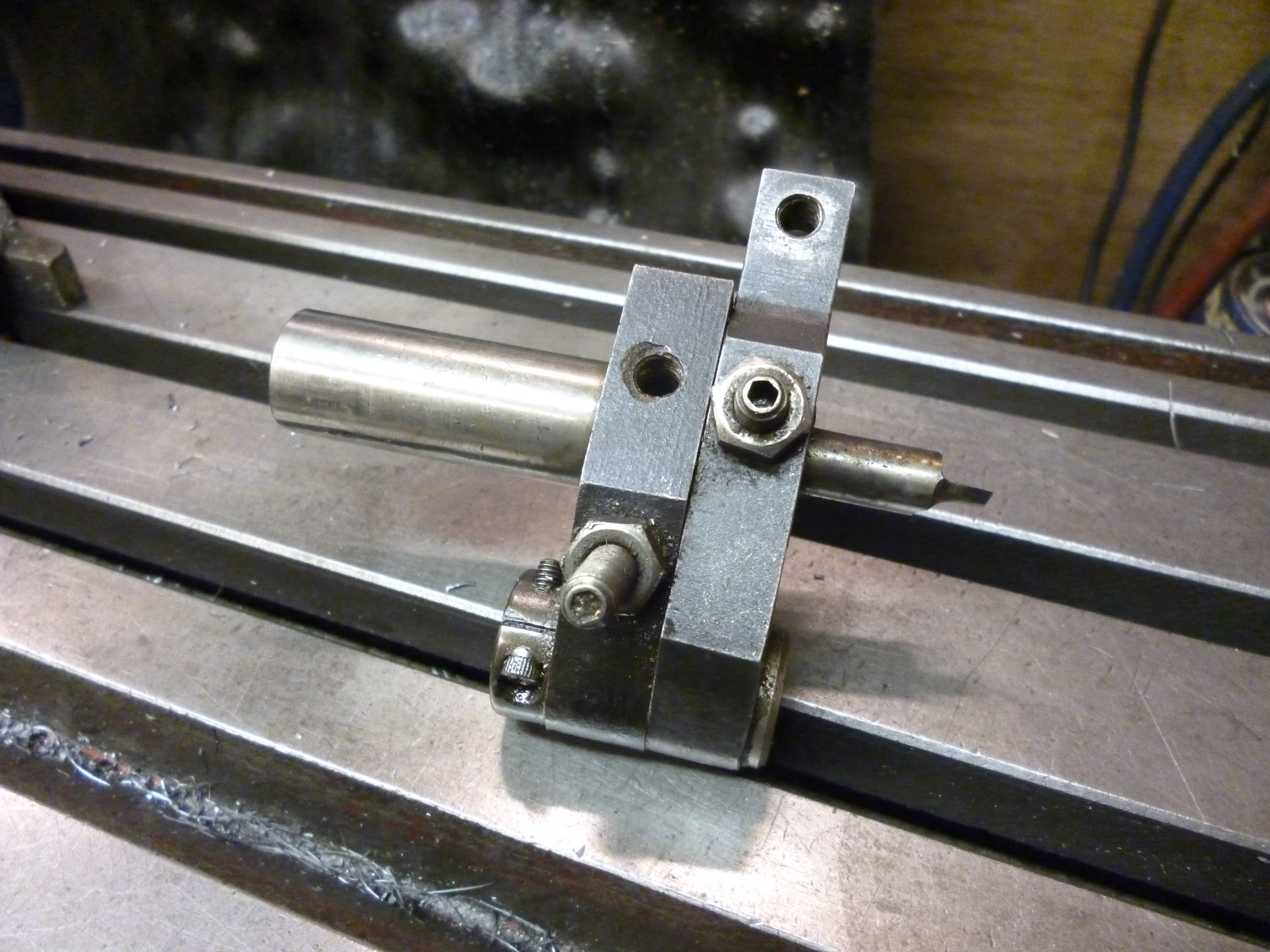
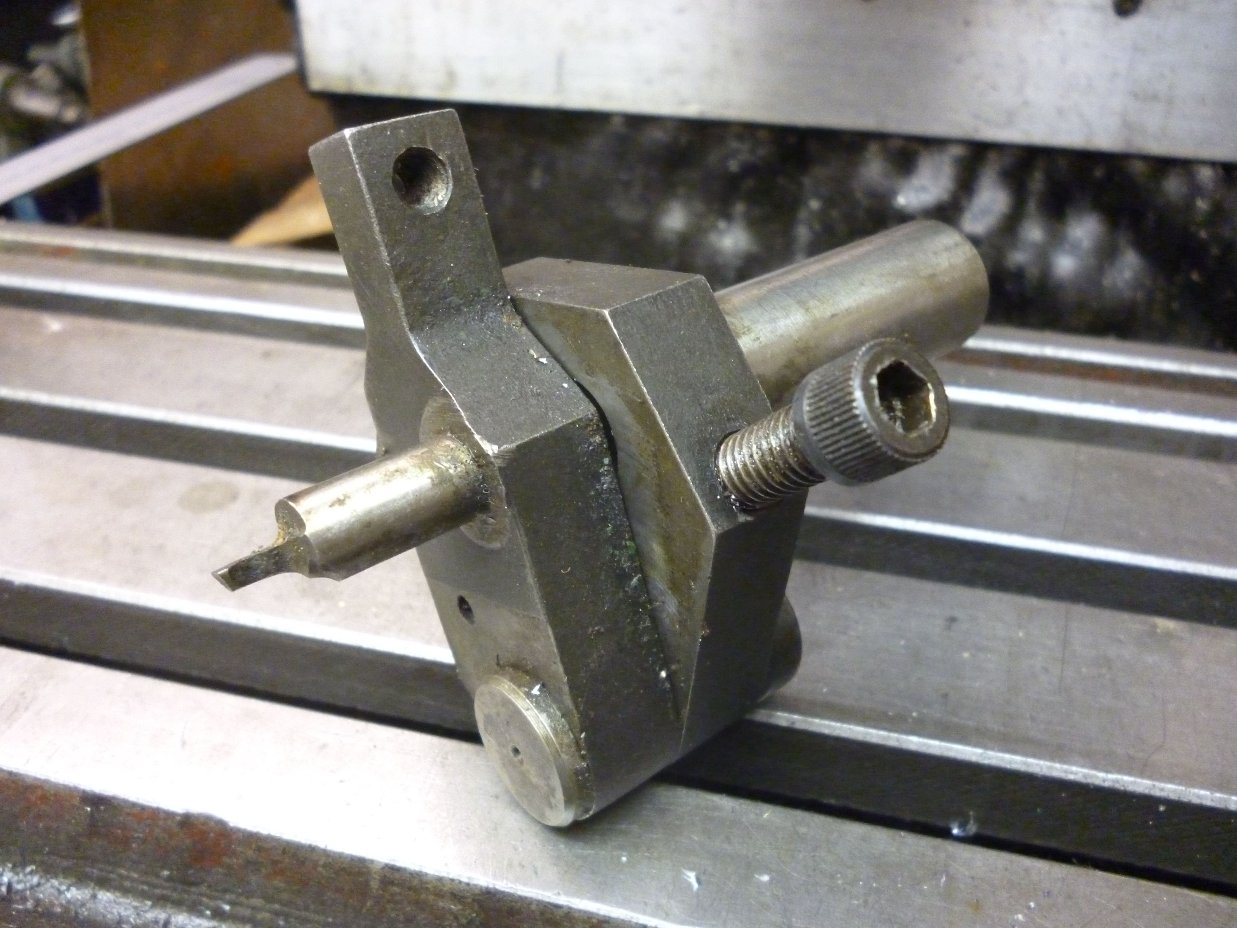
More complicated tools allowing for a screw mechanism to adjust the movement of the cutting edge in one dimension
1090 knee with screw adjustment
fig knee type toolholder with one screw adjustment
It is also possible to get knee type toolholders that use screw mechanisms to adjust the cutting edge in two dimensions.
1053 knee adjustable in two dimensions
fig knee adjustable in two dimensions
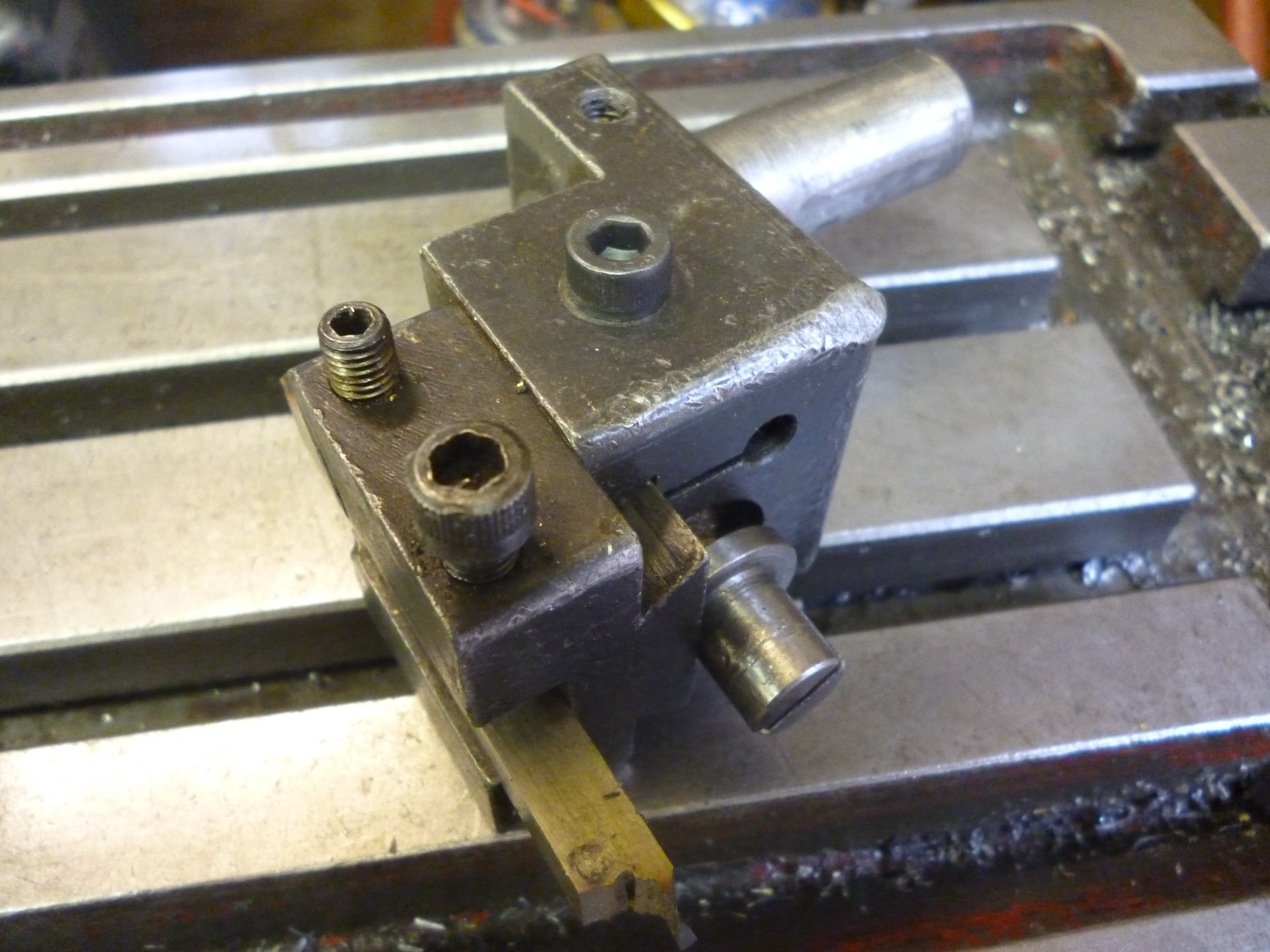
“Knees” made from parts
If is quite easy to make a “knee” by having parts that can be bolted together to make the tooling required to do the job. In general, this will be one part with a shank the fits the capstan. This holds a plate, or similar, that is at right angles to the bed of the lathe. This plate has holes in it that can be used to hold more tooling. On a capstan such a plate might have just one or two holes. On a turret lathe, where there is much more space, plates like this can have up to half a dozen holes. On these large plates there might even be arrangements to support this plate by means of a round bar to the headstock to increase its rigidity.
Tooling is specially made to fit these plates. Usually such tooling cannot be used without being fitted to such a plate.
fig tooling designed to fit a plate
It will be noticed that in the above tooling, if the shank of it should fit a socket on the capstan the cutting edge of the cutter will be pointing away from the axis of the lathe and cannot be doing anything useful.
fig shank with plate
fig shank with plate fitted with tooling
The need for steadies
Where the diameter of the workpiece has to be reduced by a larger amount then on the plain lathe this would often be done by taking off a certain amount as many times as necessary till the workpiece is close to the required diameter. The last pass would turn off just the amount needed to get to the required size and give a good finish.
Of course for each of these turning operations the cutting edge moves further towards the workpiece. This not possible on a capstan – the depths of all of the cutting edges are fixed. This means that, usually, it is necessary to make a cut that is done in one pass. This means the depth of cut needed can be larger than we would choose to do otherwise.
At the same time we are often dealing with small parts with correspondingly small diameters. In this case it is necessary to have the equivalent of a steady to hold the workpiece.
For any job it is very desirable that the outside of the bar being used is the required size and with an acceptable finish.
The need for a steady is not decided by the diameter of the workpiece AFTER it has been cut. The rigidity of this has absolutely no bearing on the matter. What matters is the rigidity of the workpiece ahead of the cutter.
Roller boxes
But very often the workpiece is very thin and needs to be supported. In this case it can be done using a roller box. This is a tool holder that includes two rollers that act as steadies. This moves with the cutter and so is equivalent to a travelling steady as used on an ordinary lathe.
roller box – 934
Fig – roller box 934
Just as on an ordinary lathe, a travelling steady can be in front of the cutter or where the cutter has just cut. If the steady is in front then the workpiece has to be round with a good finish and has to be concentric with the axis of the spindle. There also has to be a space on the workpiece for the steady to go to, but the cutter will not be able to cut there.
Fig – steady leading cutter
If the steady is just after the cut then these conditions should be true. The only problem here is that the cutter has to start cutting just before the steady can steady the workpiece. This can be got round if there is a chamfer just before the main cutting action has to occur.
Fig – steady opposite cutter
However, very often the length in front might be too short for this to work. Furthermore, often very small diameters are being turned and if is better to apply the steady as near the cut as possible. This means that, in practice, the steady is just behind the cutting edge.
Very often the steadying is done using rollers. As on the travelling steady two rollers are required.
One of the rollers will be opposite the cutting edge and will stop the workpiece from moving away from the cutting edge. The other roller is above the cutting edge to stop the cutting force making the workpiece ride up.
When the diameter of the part being turned is very small, the rollers become too big to fit into the space available. In this case plain hardened surfaces are used instead.
Fig – box using V’s
The V’s are made from two pieces of metal. It is made so it can form V’s at either end which are different sizes to the pair at the other end. The V’s are made of two parts so the steady can be adjusted individually.
This can be set up by making a part on a one off basis. This is then fitted into the chuck. When the tool is in position the two parts of the V are pushed up against the workpiece.
It is also possible to steady a workpiece by having a spigot in the capstan that fits into a hole in the workpiece. Alternatively there can be a bush with a hole in it which fits onto the capstan. This bush fits round the workpiece to steady it.
Since the workpiece is rotating it is necessary to choose the material for this steady so that it will not spoil the surface of the workpiece.
Often the rollers are not needed. In this case a roller box is a convenient way of holding a cutter. The roller can either be totally removed or just fitted out of the way.
Handedness of cutter holders and roller boxes
A cutter holder or a roller box can be left or right handed. If the top of the workpiece is rotating towards the user, the cutting edge is usually set horizontally and at the center height of the workpiece and to the front of it. Often the cutting edge will be on or near the top surface of a piece of hss. This means most of the HSS will be below the center line.
fig right handed tool holder
fig left handed tool holder
With this sort of situation, if a steady is needed then one might expect the arrangement of rollers to be as on a conventional travelling steady – one roller will be on the far side of the workpiece and one will be above.
Fig – a right handed box
Fig – a left handed box
Getting tooling for a capstan can be difficult and one often has to make the best of what is available. Left handed tooling can be used with the cutting edge in the position it lies in naturally so long as the lathe is run in reverse.
Setting a cutting edge and the steadies
Traditional tooling for capstans relied solely on the skills of the setter to get it right. There is no fine adjustment on the tools. The edge would be moved till the required diameter was being cut.
An easier way is by using a test piece with a diameter on it that was that which was required. The cutter would be set simply by moving the cutting edge till it just touched this surface.
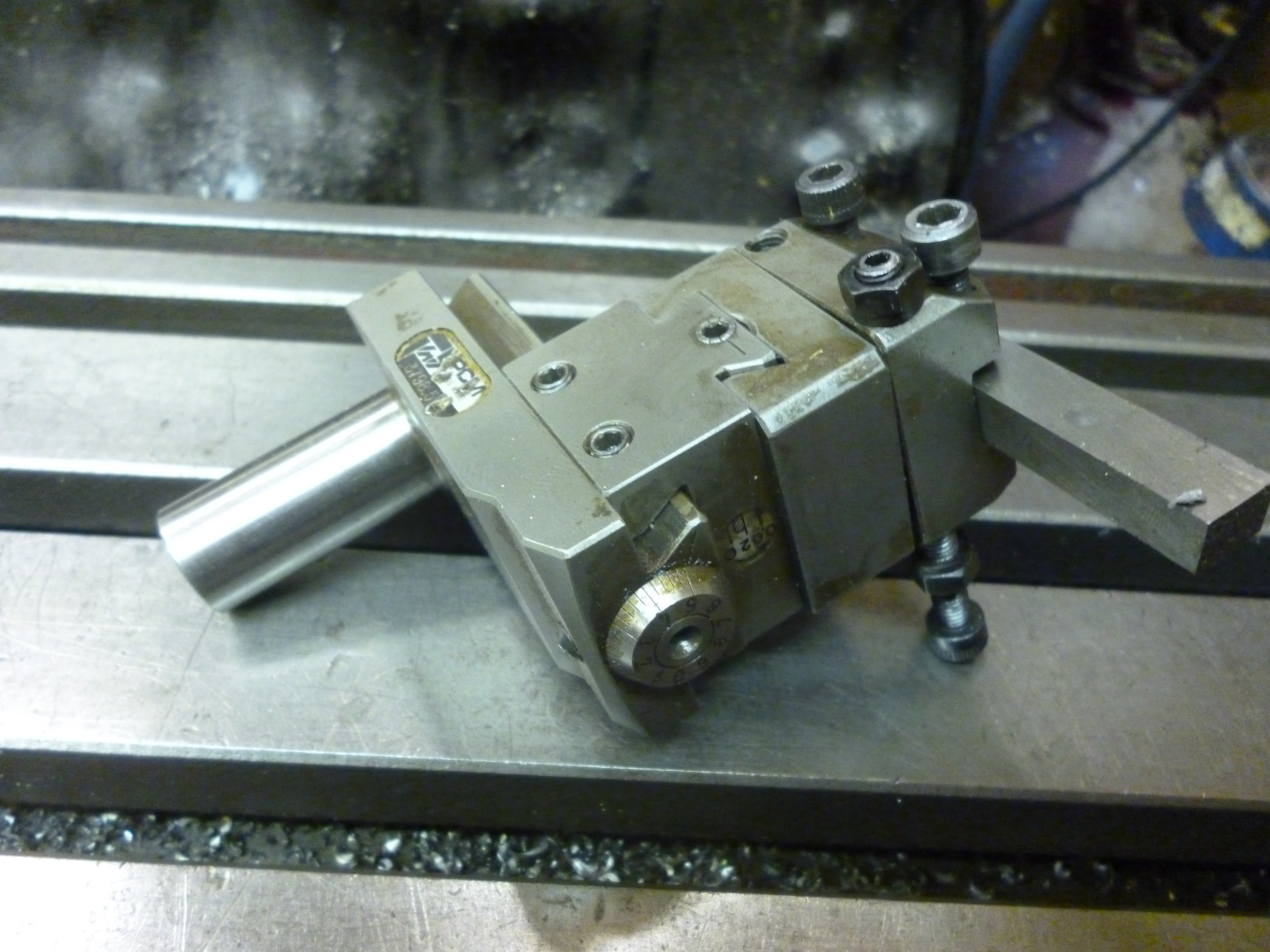
Some cutting tools for capstan use can be adjusted by using a screw mechanism. On some all of the movements are adjusted using a calibrated screw. An example of how this can be done is seen on the tooling made by the Swiss company, PCM.
One compromise is to use pieces of round HSS and hold them in small holders. These are square pieces of steel with a round hole in the center. The HSS fits this hole. However the hole does not go all the way through the holder. The other end is fitted with a screw. This has a dial on it so the screw can be turned by a very precise amount. As the screw turns it pushes the HSS out of the holder.
Fig – adjustable cutter holder
The HSS has a flat on it to stop it rotating. When cutting the HSS is clamped in position.
Grooves on the end of a workpiece
A tool in the capstan could cut grooves in the end of a workpiece but this is not very useful.
Chamfers
A cutter fitted to the capstan can be used to cut chamfers.
Swing tooling
Swing tooling fits on the capstan. Like all other such tooling, it moves from right to left. Usually it does not cut during this movement. But, when it hits the stop, it has a cutter that “swings” in or out. This is often used to cut internal or external grooves in the workpiece.
4324 capstan swing 1
fig swing cutter
1080 capstan swing tooling
The movement in or out can be done either by the operator moving the swinging part directly by hand or by a pusher fitted to the cross-slide.
Problems of setting up tooling on the capstan
The problem with setting up the tooling on the capstan is that it is very easy to set up any individual tool but each piece of tooling has to operate on the workpiece which is in one particular position. Consider if a drill chuck is used to hold a drill bit the front of the chuck might be 150mm from the capstan. On the other hand if a collet chuck is used to hold a drill bit the front of the chuck might only be 50mm from the capstan.
Of course the whole capstan unit can be moved anywhere but this moves everything equally. And the capstan tooling might move 100mm. If the workpiece is less than this then this can be used to compensate for some tooling being longer than other bits.
In the end it will be found that it does not follow that the setup required can be done with the tooling available.
The Cutoff slide
If we are making a whole series of parts from a single bar of material how they get parted off becomes an important point. We can, of course, use a parting tool in either the front or rear toolpost on the cross-slide. Another option is the cut off slide. This is a bit like an extra saddle fitted between the chuck and the usual saddle. It is fairly narrow, say, 50mm. Its function is primarily to hold a parting tool for parting off the workpiece.
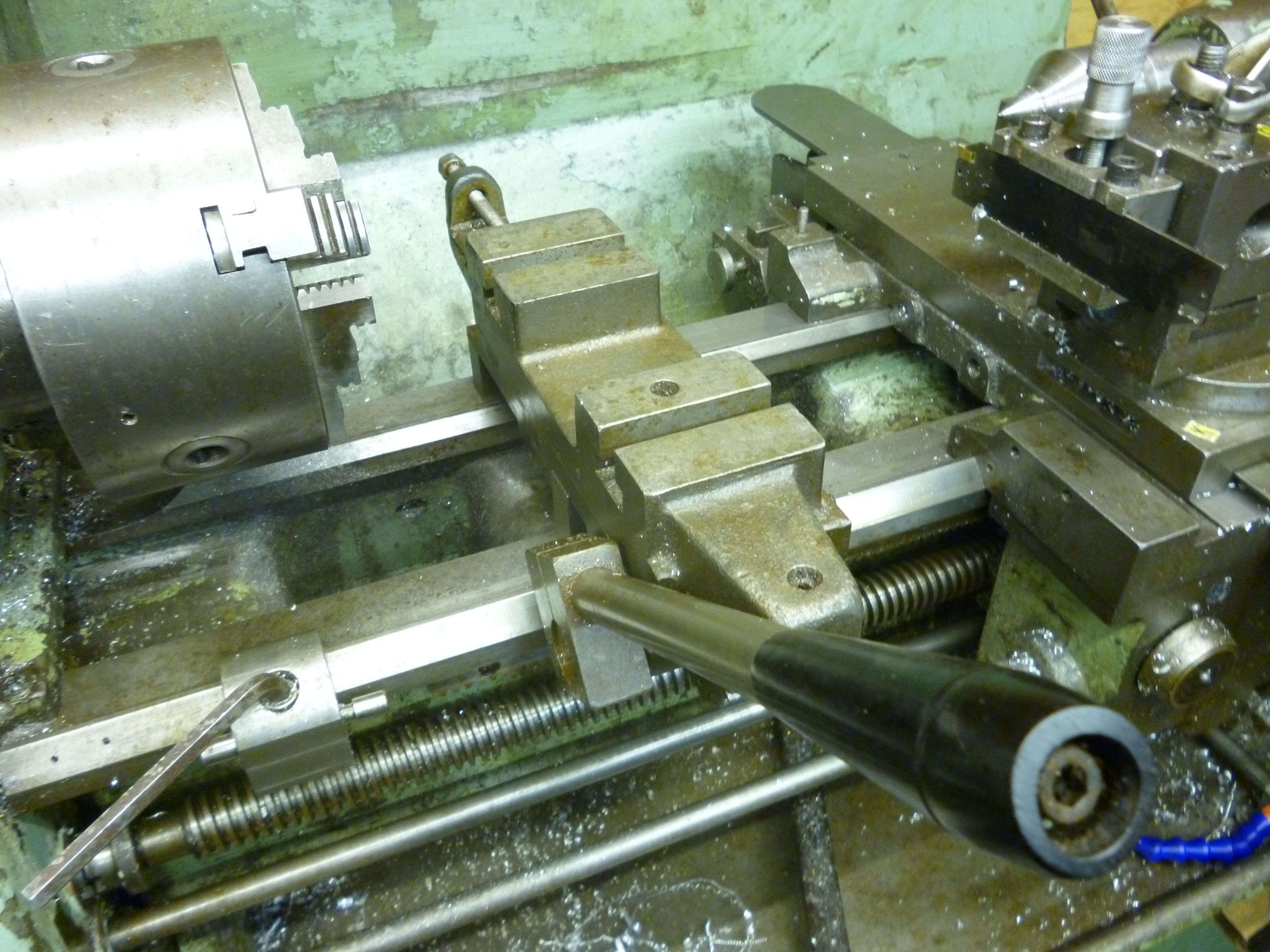
cutoff slide – 970
Fig – the cutoff slide 970
(The cutoff slide shown was made for a lathe with a much smaller center height. The two blocks raise the slide so the surface for the tooling is at the same height as that for the top slide of the lathe.)
It is however it is also different in that it does not have a screw feed like the cross-slide. It is moved to and fro by means of a rack and pinion system. This is far easier than screwing a handle and, far quicker.
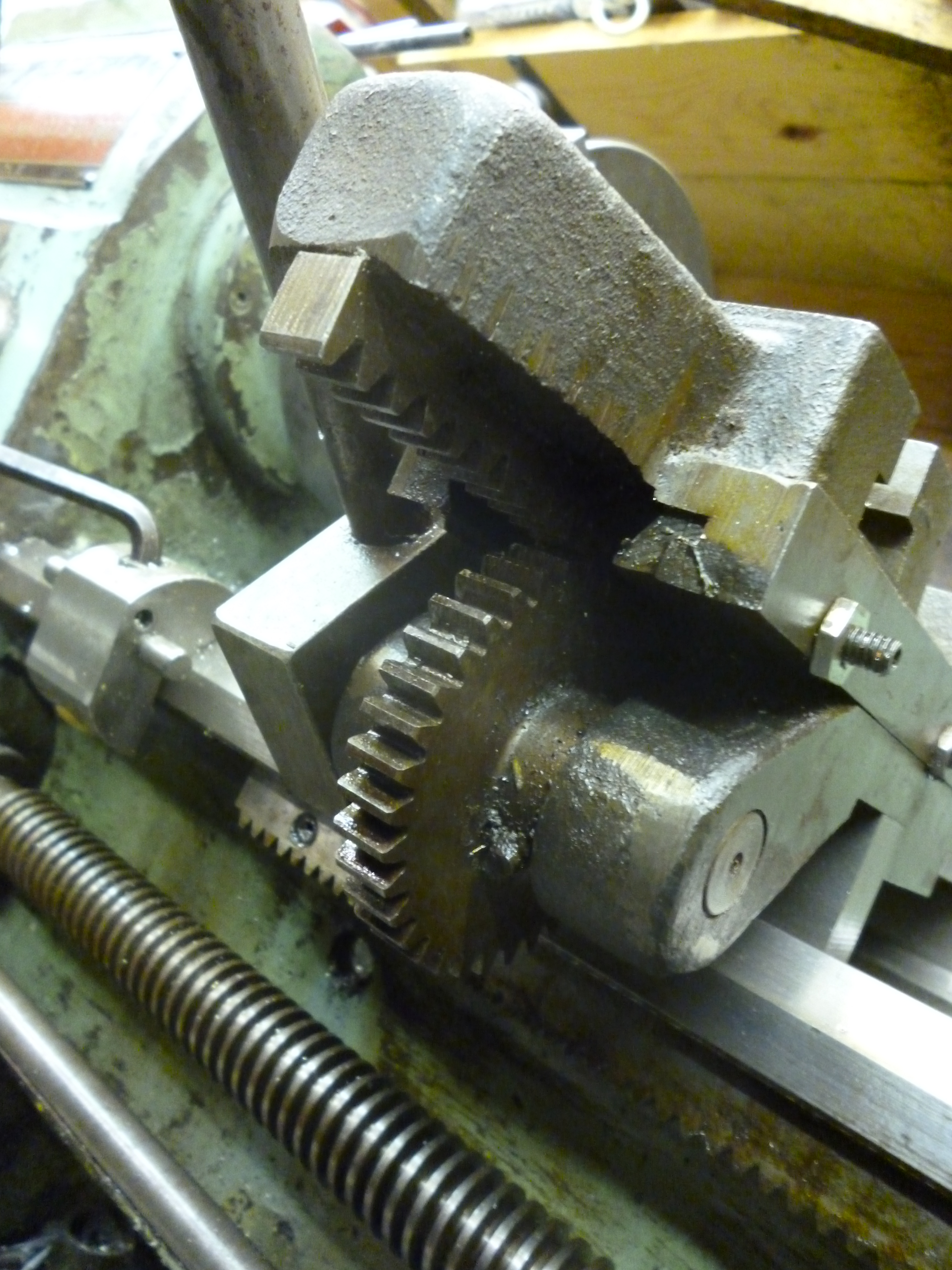
cut off slide – 971
Fig – rack and pinion mechanism seen from underneath 971
All of the tools on the capstan moved from right to left. There are no tools that move in and out.
For making small part the most efficient way is to make them from a bar. This is, of course, only possible for bars diameters that fit into the bore of the lathes spindle. In this case the last step in making any part is parting it off the bar.
With a new bar the parting tool might also be used as the first tool – to clean up the end of the bar.
If there is a tool on the user side of the workpiece it is inevitable that one can just as easy to put another on the far side. One will always be for parting off. But the other can be for any one of a number of uses. This is very useful because cutters in the capstan can, without complication, only cut along the bed of the lathe whereas a cutter on the cut off slide cuts at right angles to the bed.
It is also possible to use a tool mounted in the rear tool post. It is usually more difficult to change this so, in practice, this is the only one available. To be able to use only tools already in position clearly saves time.
If two tools are being used on the cutoff slide then it usually makes sense for the one at the back to be held upside down. This means it can be used without having to reverse the direction of the motor.
If the tool at the front is a parting off tool then it is inevitable that the one at the back will be to the right of the one at the front. This might seem to mean that the parting tool should be right on the left of the cutoff slide but if there are tools on the cross-slide being used then the gap between the parting tool and the tools on the cross-slide becomes important.
In some cases, in order to use the cross-slide most effectively, it might not be practical to use the cut-off slide.
Parting
High speed steel blades can be very useful when the diameter of the workpiece is small and thin blades can be used. For larger diameter workpieces where wider blades are needed it can be useful to use carbide inserts held in a specially made blade.
Fig – Sandvik blade with carbide insert
Parting can be done using a HSS parting tool.
Fig HSS parting tool
It is also possible to use to use a carbide insert held in a special holder.
Fig carbide parting tool in holder.
The shape of the parting tool
Carbide parting tools
These are best used as supplied. It is possible to buy them so the end is straight, to the left or to the right.
If the parting tool has a cutting edge that is square then it is hard to get a clean finish on the part being parted off. The solution is to have the end at an angle.
Fig – end of parting tool at an angle
If this is set so that it merely finishes the bottom of the piece being parted off then there will be a pip on the start of the next workpiece. All that needs to be done is for the parting tool to cut off the workpiece and then continue long enough to remove the pip.
If a cut-off slide is used it is locked in position. The saddle and its tool posts do not have to be used at all. But if they are the saddle should be locked.
On both nuts and bolts the surface that appears to need parting is actually not flat. In the case of the nut both corners are chamfered. In the case of a hex bolts the hex is chamfered but the end of the thread is rounded.
Of course the left hand end of one component is the right hand end of the next component. This means a single modified parting tool can be used to produce both the left hand end of one part and the right handed end of the next part.
It would be nice to have a parting cutter shaped as shown
fig required parting tool
This is almost impossible to grind by hand to the accuracy required. The way round this is to cut the shape using two cutters. The first is as shown.
fig
This simply cuts the chamfer of the left side of the last nut and the right side of the left nut. The depth of cut is important.
fig cut produced
The second cutter is simply a parallel bladed parting tool
For a nut of any particular size the sizes of both of these cutters is important.
With a capstan lathe the balance of “costs” is different. It could we be worth adapting a parting tool is it saved performing an extra operation elsewhere. This is so with parting. The two most obvious uses of a capstan to make nuts and bolts are both cases where using a straight parting tool might not be the best way of doing the job.
Grooving
An important example of a job that can be done using the cut off slide is cutting grooves in the side of the workpiece. Since the cutoff slide is fixed in position for parting off. This leaves just one other cutter it is only possible to cut one groove in the workpiece.
To try to use the parting off cutter in more than one position is rather to defeat the whole purpose of using a capstan though there might be a particular situation where it might make sense.
A cut off slide will have stops fitted on it. A stop is not really needed for parting off but it is essential for setting the depth of a groove.
Form tool/profiling
A form tool is one where the cutting edge is specially shaped so as to be able to produce a surface with the same shape.
The use of this on the end of the workpiece, ie the tooling is in the capstan, it limited.
On large industrial lathes it is possible to use form tool to cut complicated shapes. This only works because the machines are very rigid and powerful. On small lathes the length of cut of a form tool is very limited before vibration and chatter make it useless.
Chamfer
The chamfer is one exception. This is useful since, with a capstan, operations by the capstan are easy or more available than ones from the cut-off slide.
Very short tapers
Whereas a chamfer would normally be at 45 degrees any other angle could be made. This would form a taper.
A form tool is a good way of making small internal/external round shapes. See later under making valves.
Fig form tool for making round shapes.
Where a shape is required that is too long to be done by one cutter it is quite possible to split it up and do it in sections using more than one cutter.
Profiles with form tools
tapers
Can be done using a form tool but only one way round
The cross-slide
Many capstan type jobs can be done using just the capstan and a cutoff slide. In fact many small lathes specially designed for doing just capstan type work do not even have a cross slide. On a larger machine the turret or capstan might have enough movement to be able to take a cross-slide. On a ordinary lathe fitted with a capstan it will have a cross slide. It cannot usefully be fitted with a cutoff slide and a cross-slide because a cross-slide tool cannot reach the part of the workpiece next to where it is parted off. Furthermore the capstan tooling cannot reach across both the cutoff slide and the cross slide. On the other hand if there is no cutoff slide the cross-slide can do most of the same tasks though less easily.
On a large turret lathe it might seem that the best arrangement here is a quick change toolpost. Though this is usually the most flexible arrangement for ordinary turning jobs, when making large numbers of identical parts there are other factors to consider. The usefulness of any of a large number of tools is limited. What is more important is the speed of changing between relatively few tools.
The quick change tool post with its toolholders is also much bigger.
On a large turret lathe the best arrangement is the four way toolpost. To be useful it is essential that it is properly indexed. It also needs some sort of system of stops
Fig – an indexed four way toolpost with stops
See Easy Changing of Lathe Tools, Philip Amos, MEW 81, p16
What is needed is a toolpost that is firmly bolted to the topslide even when the four way tool post is completely removed.
Fig – modified toolpost
The usual toolholder is a loose fit on the tool post. A toolholder that always repeats the same position has to be a good fit onto the tool holder. It is also necessary to have some sort of indexing arrangement. This can be made by fitting a plate to the toolpost but under the toolholder. This has keys on it so it always fits the topslide at the same angle.
It also has four holes in it. There is a pin in the toolholder can fit in any one of these but only when the toolholder is in the right position.
Fig – indexing plate
The cross-slide can, of course, move in either the z, along the bed, or x, across the bed, directions. Either way, for efficient operations any movement will require stops for each possible tool. But there is another consideration. Movement along the bed can be done quickly and easily using a few turns of the handle. Movement across the bed requires many turn of a small hand wheel.
Stops for the four way tool post – x direction
Setting up a set of stops in the x direction for the cross slide is difficult and then they have to be turned manually. But it can be got round. The differences between the depths of the cuts in the x direction are often very small. If there is one stop for all of the cutters on the cross-slide in the x direction then differences in the depth for each cutter can be achieved by adjusting the position of the cutter in the fourway tool holder.
Fig single stop for all of the cutters on the cross-slide
It is easy to fit stops to the four way toolpost. One part of the stop is bolted to the bed of the lathe. The other part, which is different for each tool, is fitted to the four way toolpost. This is done as shown.
Fig – stops for the four way toolpost
The great merit of this is that in turning the toolholder the stops change automatically.
A four way tool post cannot hold four full length tools. It is possible only to hold two. However they can be cut down or special short tool holders can be made.
One of the key advantages of using a quick change toolholder is that each toolholder can be individually set to set the height of the cutting edge. The four way holder does not have any mechanism for setting the height of the toolholder. Each one has to be set individually. This is usually done by placing pieces of thin metal below the bottom of each of the toolholder. These thin pieces of metal are often pieces of a hacksaw blade.
Usually a four way tool post carried four different cutters. But when used in conjunction with a capstan it can be used for other purposes. One example of this would be a guide to move a tool in the capstan in a certain way, for example, to cut a curve or a taper.
Problems with the four way toolpost
The width of the fourway toolholder is approximately the same as the working distance the capstan can move. This means that it is not easy to ensure that the capstan tooling does not clash with the fourway toolholder.
Complex tooling arrangements
So far we have looked at various forms of tooling where only one part of the system is used to achieve some certain cutting action. For example the tool on the capstan is moved forwards to make a cut. This is independent of the toolpost or the cut-off slide.
However it is possible to use the capstan and the toolpost together. This can be used to make long tapers. Suppose we have a tool fitted to the capstan that is hinged so it swivels in the horizontal plane. It is fitted with a pin which is then fitted with a bearing. This bearing rolls along a template fitted to the toolpost.
Fig – using the capstan and toolpost together 933
Using a cut off tool on the cross slide
In general on a universal lathe with a cross slide it will be impractical to try and fit a cutoff slide.
One alternative is to fit a cutoff slide on the cross slide.
fig cut off slide fitted to the cross slide

I have found these pages interesting to read and full of useful information. Unfortunately, many Figs were missing so I couldn’t see the matching illustrations.
I’ll try and do something about this tomorrow ie tuesday.
john f
An excellent piece of work. Very informative and useful as I use a capstan frequently on my Colchester Bantam. This extends the range of work I can do competently.
Thanks. Is it your capstan that extends what you can do or my article?
Let me know if you find anything wrong or missing.
john f
Very informative but a lot of figs were missing.
Hi,
Thanks for the comment. Yes I know. The problem is that wordpress is totally useless in helping to maintain a site with a very large number of photos.
I gave up on updating this site some time ago.
however I thought the bit on capstans was such that I could extract it, add the missing photos and put this as a book for a nominal amount on amazon or such.
john f
Hi Folks
I am making replacement bolts for a 1931 Rolls Royce where the original ones were lost or damaged. I figured it might be simpler to do this than try to find the right BSF bolts and nuts during the current climate!
I have a colchester lathe and a coventry Dia head with A M 5 Chasers for thread cutting.
The bolts will all have square heads and need to be turned down from square section steel sized to suit as early RR spec. Some bolts (engine to gearbox) are 4″ long, need to be turned down to +001″ prior to cutting the thread.
Question: Is there a steady type cutting tool that could be mounted in the tail stock that would reduce the square section to size in one operation?
Suggestions would be very much appreciated.
Thanks
RIchard
Sorry about delay but had to think about this
firstly you need to make a split collet that will fit into a collet in an er type chuck.
the split collet is to hold the square bar
This chuck is mount coaxially in a four jaw chuck.
This would apply whether you were using a capstan or not.
The problem lies in turning down a square bar to a round part accurately.
This can be done on a capstan but only if the workpiece is rigid enough to be turnable without flxing.
There is no center on a capstan lathe that can be used whilst turning the workpiece unless
there is a center locked in one position then the turning is done using the usual lathe toolpost
to hold the cutter – could be interesting.
on the capstan a job like this would be done using a roller box whereby the rollers
act as a steady but this usually only works because the workpiece is round to start with.
not using the capstan
workpiece in chuck sticking out 4+ inches
center drill
use roraqting center in tailstock to hold it at end
turned down roughly without steady
turn down to diamter long enough for fixed steady to hold it
turned down to final diameter using fixed steady.
hope this helps
john f
Re the RR bolts, would it be possible to make a box tool that has a bush with a square hole to take the work inside a bearing ?
You need a bush that holds it in three point so two are always touching. you might need to do it in two cuts so you need two capstan positions each with the same sort of bush but different sizes. The bush will need to be ahead of the cutting edge so you might even need a third position to finish the second cut
john f