Number of tools
When the capstan is in use it is also possible to use any tool that happens to be in the front toolpost. But, of course, changing these is time consuming. Furthermore whereas tools in the tailstock each have their own stop, tools in the front tool post do not. Even if there are stops on the cross slide they do not turn automatically.
But, we always have to consider doing as many operations at once. Though a drill bit can be held in a drill chuck this would only be doing one operation. It is easy to make tool holders that do something else and hold a drill bit. Another advantage of this is that the position of the cutting edge of a tool is always critical. With a drill chuck the position of the cutting edge of the drill is not very flexible. But, more importantly, the distance from the capstan to the end of the drill chuck is large. This means that all the other tool holders will have to be similarly long in order to reach the work piece. With six tools sticking out a long way things are going to clash.
For each step the stops would be set as necessary. If the movement of the capstan is up to 100mm then each stop might have to be adjusted over this range. It is useful to make a tool for setting these screws easily.
The idea is that each operation is controlled by a stop so the user would then not worry about how far to move the tool. He would just move it till he hit the stop.
The knee
The knee is a forging that has a shank to fit the capstan. If it has an arm that can hold a piece of HSS which will cut the work piece from the end and along parallel to its axis.
It is easy to see that if the shank has a bore in its center then this can be used to hold a variety of cutters, but in particular, drills bits. Since the bore is a fixed size it is necessary to make bushes to fit the drill bits that need to be used.
Fig the knee
Very often the workpiece will be made from the end of a long bar. When it has been finished it is parted of. Parting off is an operation that does not use a slot on the capstan. Parting off can be done using the tool holder on the cross slide or by using a rear tool post to hold the parting tool.
It is often necessary to cut a shoulder on the end of the workpiece. This can be done with any tool holder that fits the capstan.
Multiple operations in one step
It is possible to increase the number of jobs that can be done in several ways.
Operations at right angles to the axis of the lathe
The cut off slide gives two possible operations though one will invariably be parting off. The other could by chamfering or cutting a groove.
Tooling on the saddle could also be used.
Cutter on the capstan could be operated manually to move at right angles to the lathes axis.
It is very useful to have a small notice board that tabulates all the steps, the tools being used, the speed of the spindle and its direction of rotation.
Second operations
There are many times where a turned part cannot be completed with the workpiece being machined in one setting. An example of this would be a stud with a thread on either end.
The first operation would be to use bar feedstock. This would be threaded on one end and then parted off to the required length. When the required number had been made like this the lathe would be setup for the second operation. This is very different. For a start whereas the first operation used a bar the parts now are separate short lengths.
The best way of dealing with short lengths is to hold the workpiece in a collet but the collet has a stop built into it.
Fig stop that fits a collet chuck
The chuck is fitted in the four jaw chuck and carefully centered.
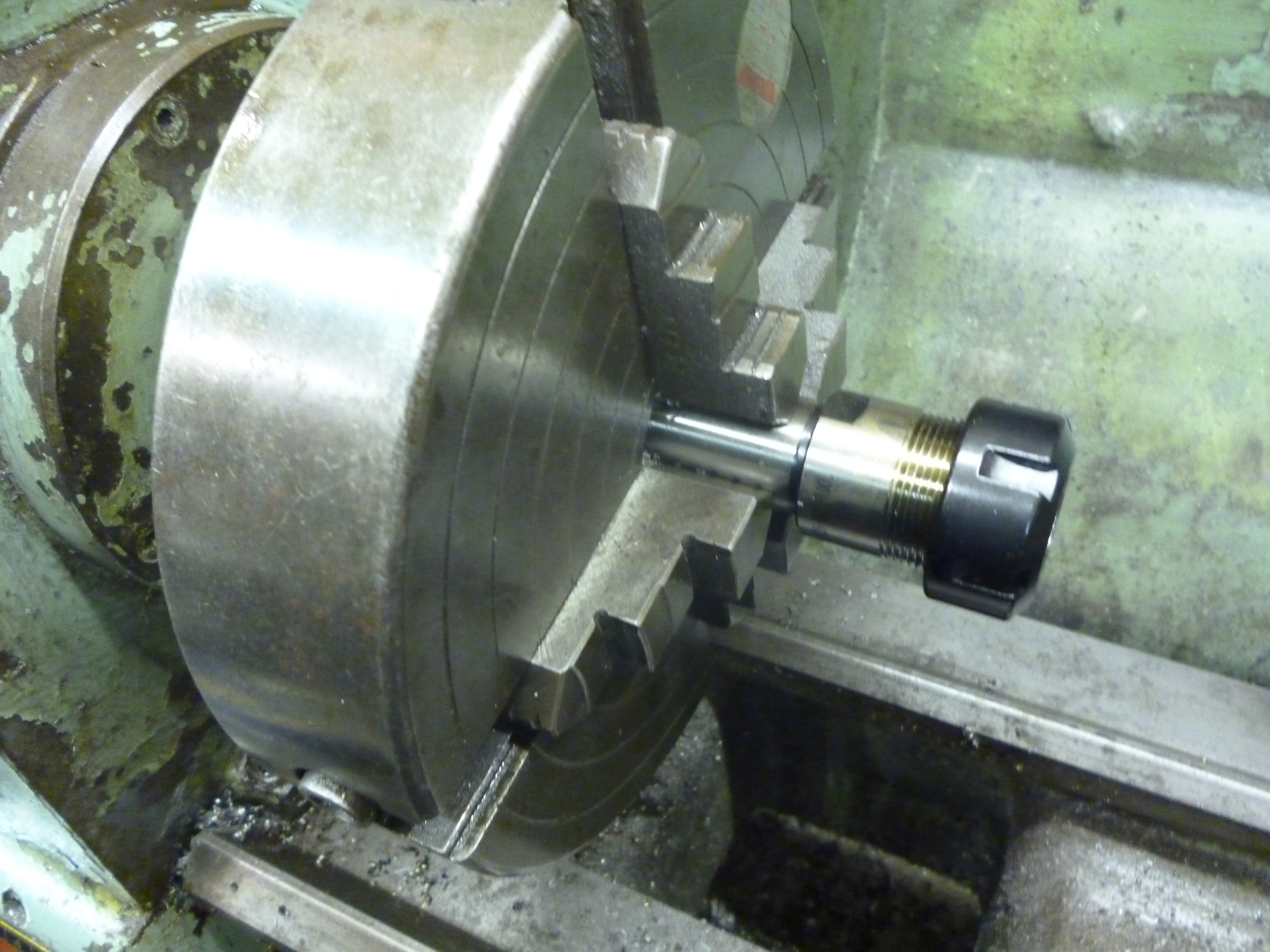
ER collet chuck in four jaw chuck 939
Fig center chuck being held in the four jaw chuck 939
When the workpiece is placed in the chuck it is pushed in as far as it can go. The chuck is done up like this. The capstan is then used to cut the thread and finish the part.
When the part undergoes the first set of operations all the surfaces will be concentric one way or another. It is usually essential that when held for a second operation that it is held so it is concentric.
This means that if the first operation is done in a three jaw chuck so long as it is machined all over it can be turned round but has to be held in a collet.
If it is not concentric after the first part it will not match up whatever happens in the second part.
If the first operation is done in a collet then if the second is done in a collet it will match up.
In the examples the capstan is sometimes used when it would appear the job could be done with one tool in the tailstock. The point is that given the capstan is already in place, it is far easier to feed a tool using the capstan instead of using the tailstock.
Example
Finishing a stud
The capstan holds the die holder. The collet has a depth stop fitted to it. The stud is fitted in the collet chuck. A thread is put on the stud. With a die in the capstan. The stud is removed from the chuck.
Finishing a drill bush
The capstan holds the countersinking tool. The drill bush is fitted into the collet chuck. Since the bush has a rim the collet does not need a stop in it. The countersink is used to form a chamfer. The bush is removed.
Finishing a screw with a slotted head
The slotted head on a screw is best finished on a milling machine. The screw is held in a piece of round rod that has a thread to take the screw. The thread goes all the way through. The hole is fitted with another screw that is locked in position. This set the depth to which the workpiece will screw in.
The screw whose slot is about to be cut is also locked in place with a locknut.
The slot is cut with a slitting saw fitted to an arbor.
Fig slotting saw fitted to a stub arbor
For small screws the width of the slot is very small. Cutters are made to the correct sizes for small screws. But the hole for these are quite small and a sutiable arbor is needed for these. This can be held in a collet chuck.
Fig small slitting saw held in arbor held in collet chuck.
Screw cutting lathes
Automatic lathes
Footnote
Bibliography
Capstan and Turret Lathes Setting and Operating – E T Westbury, Percival Marshall
Newnes Complete Engineer vol 2, p554-588,
Turret Lathe work, Alfred Herbert Ltd, Coventry
Turning and boring, Mechanical Engineers Library, The industrial Press, Chapter V
Appendices
Details of four way tool post
The key to the fourway tool post is that it is indexed. The aim is that each time it rotates each tool is exactly in the same position as it was the previous time. This is achieved by the toolpost have a round shape on the bottom. This fits into a round shape on the plate below. The plate below is bolted so its position is always fixed.
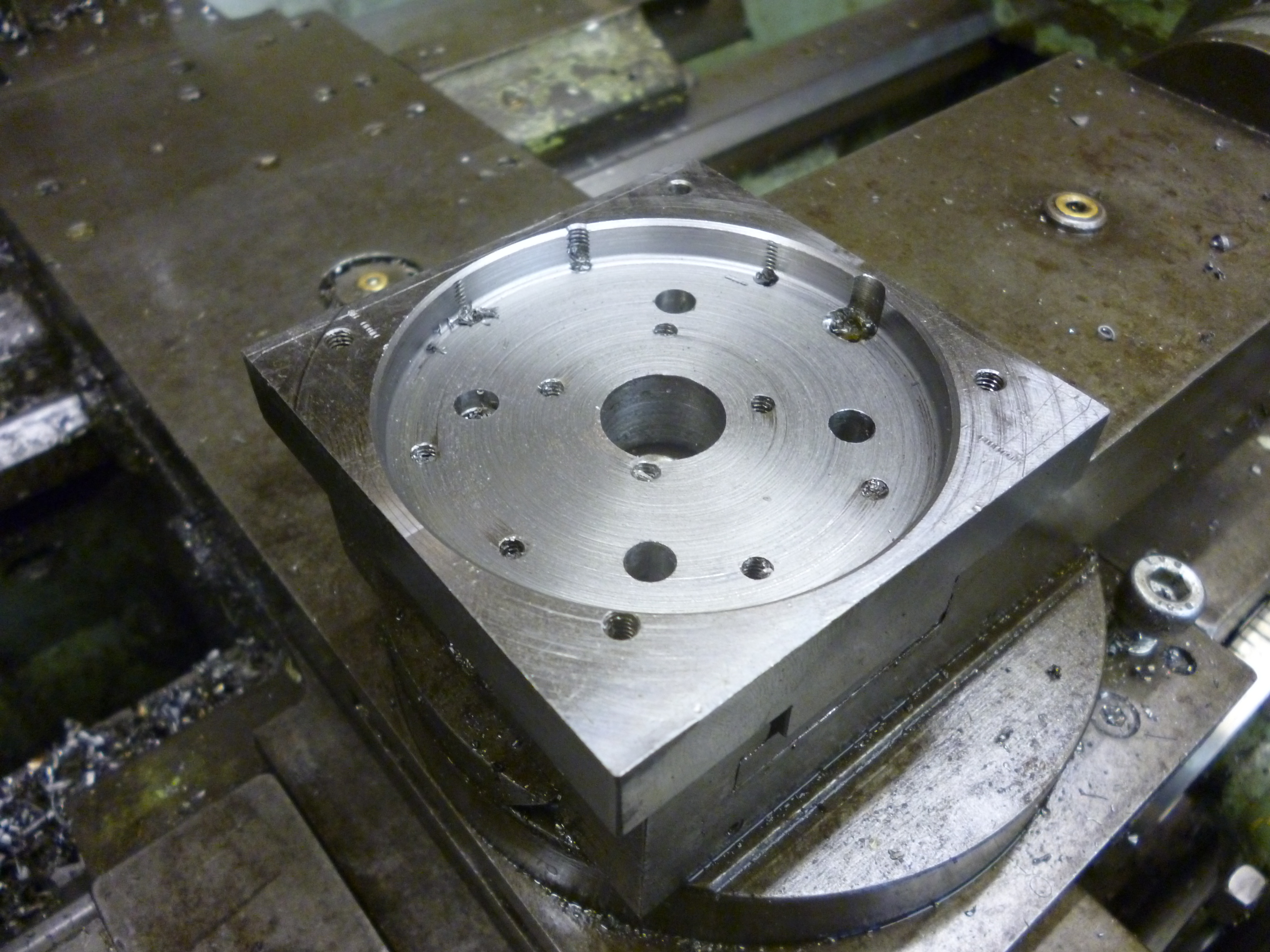
A base is made that fits into the T-slot on the topslide.

base of four way tool post – 941
Fig base fitted to the topslide 941
The bottom plate fits in the top of the T-slot and
bottom plate of four way toolpost – 942
Fig 942
is bolted with some studding to the base

base with bolt – 943
Fig 943
The toolpost fits on top of this.
The four way toolpost is just a convention fourway toolpost except the bottom is not flat it has a round shape that perfectly fits the hole in the base plate. It has the standard slots all the way round to take the tools. Of course there are holes on the top side to clamp the toolholders. But there are also matching holes on the bottom side. These take cap screws that can be used to alter the height of the cutting edge.
There are also holes on each side at the bottom to take the stops.
The odd hole in the top surface is the hole for the index pin
The toolpost has a hole drilled and reamed that takes the indexing pin. This is drilled through into the bottom plate in four position at 90 degrees intervals. It is essential that this pin is a good fit in each of these holes. This can be done by clamping the toolpost to the bottom plate. Use a transfer punch to mark the center of the hole on the bottom plate. Drill through the hole in the toolpost and into the bottom plate with the reamer size drill. Then, whilst still clamped together go through the toolpost then ream the hole in the bottom plate. Do this for all four positions.
To rotate the toolpost, lift out the indexing pin, loosen the bolt, rotate the toolpost whilst pressing the indexing pin. This will slip into the next hole. Clamp the toolpost to the bolt.
Sharpening diehead dies
It is said that diehead dies should only be sharpened using the jig specially made for doing this. Needless to say there is a different jig for each different size of diehead.

a well used die 950
Fig well used die 950
Index
