Making a cylinder block with piston valves
This covers making a cylinder block with piston valves from end to end. If the cylinder block has slide valves then only the differences from this are covered on another page.
The first assumption is that buying castings is too expensive so the block will be make from a lump of cast iron.
The first task is to produce a block of cast iron that will enclose the cylinder block to be made. By this what it meant is that if this block was a hollow box then the finished cylinder block would fit inside it.
Making blocks is covered elsewhere.
The first step is to mark out the block showing where the cylinders for the piston and the piston valve are to go.
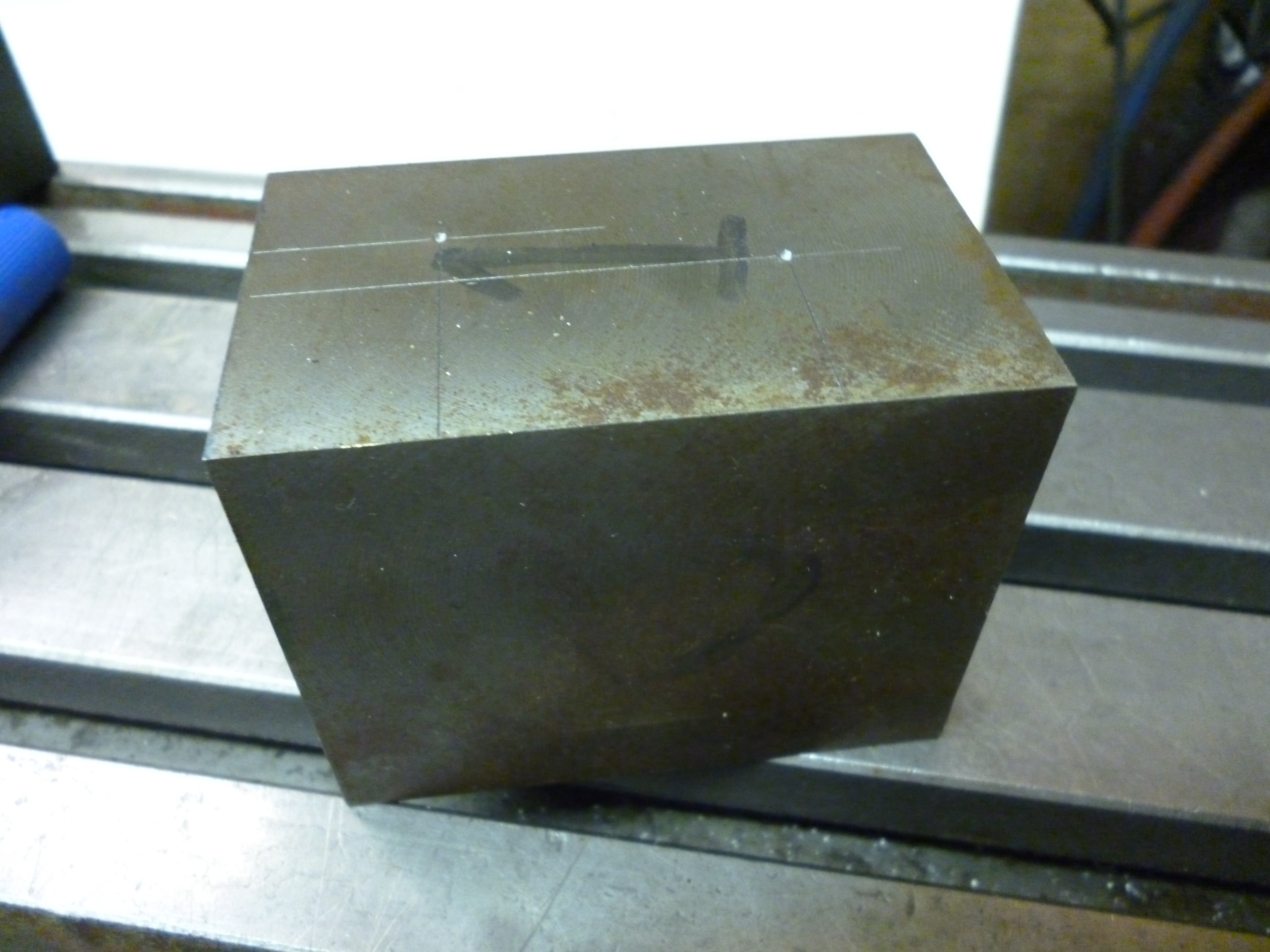
fig 2406
These marks are then center drilled.

fig 2407
This block is then mounted on a Keats block and this is fitted onto the face plate on the lathe.
A Keats block is really just a v-block fitted to an angle plate. If a Keats block is not available it would be possible to clamp the workpiece onto an angle plate mounted onto the faceplate.
It will be noticed that the side of the Keats block has slots going, in this case, up and down. The bolts holding it onto the faceplate are going in/out horizontally. This means any point within a large area, which includes this workpiece, can be moved easily to be in line with the tailstock.
The live center in the tailstock is used to align it whilst the bolts are loose. They are then tightened up.
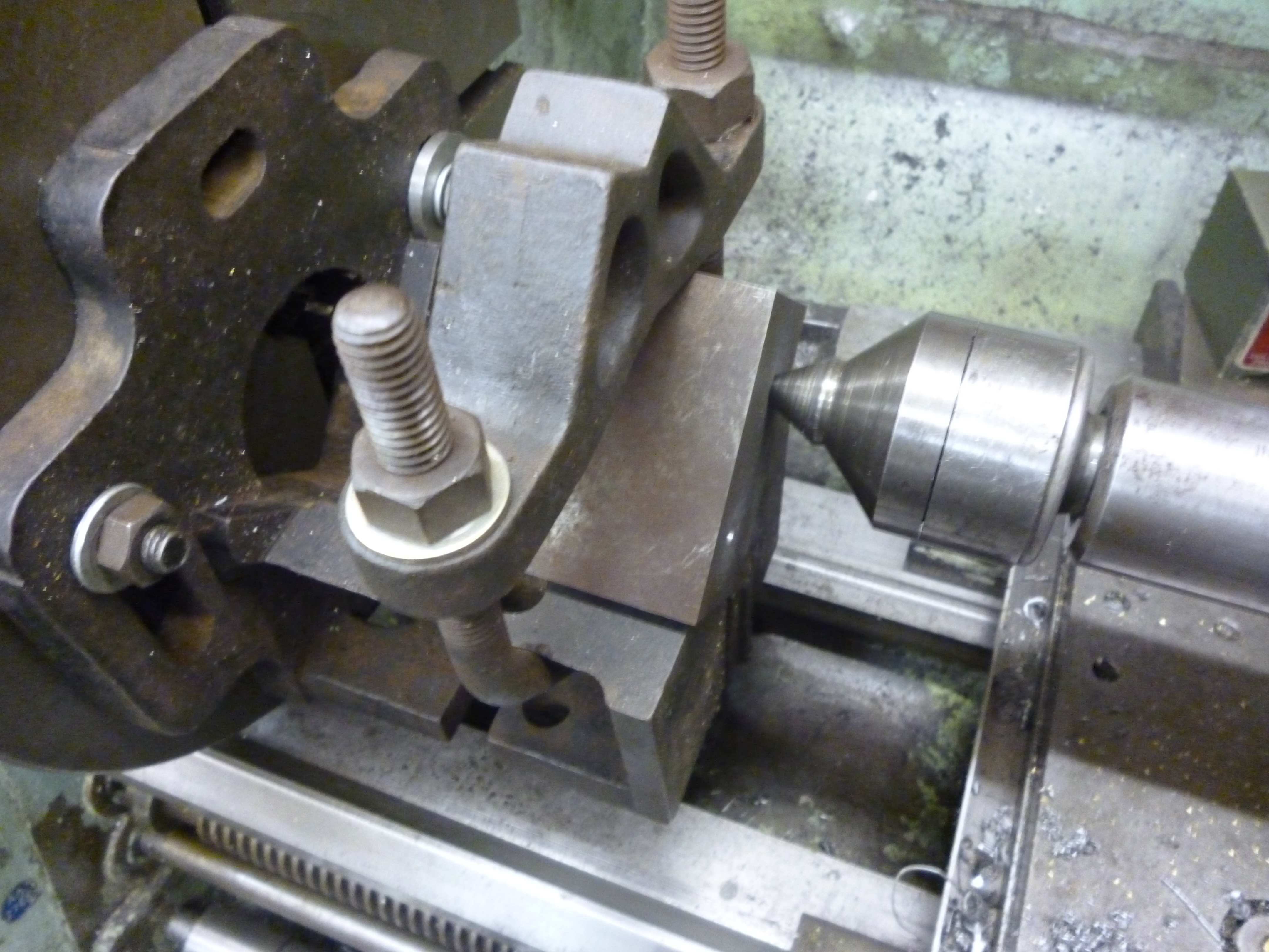
fig 2415
It is then possible to drill with a small drill, about 6mm, a hole. This just makes it easier to then drill it with a large drill.

fig 2408
The hole is then drilled with a drill that will make a hole suitable for reaming.
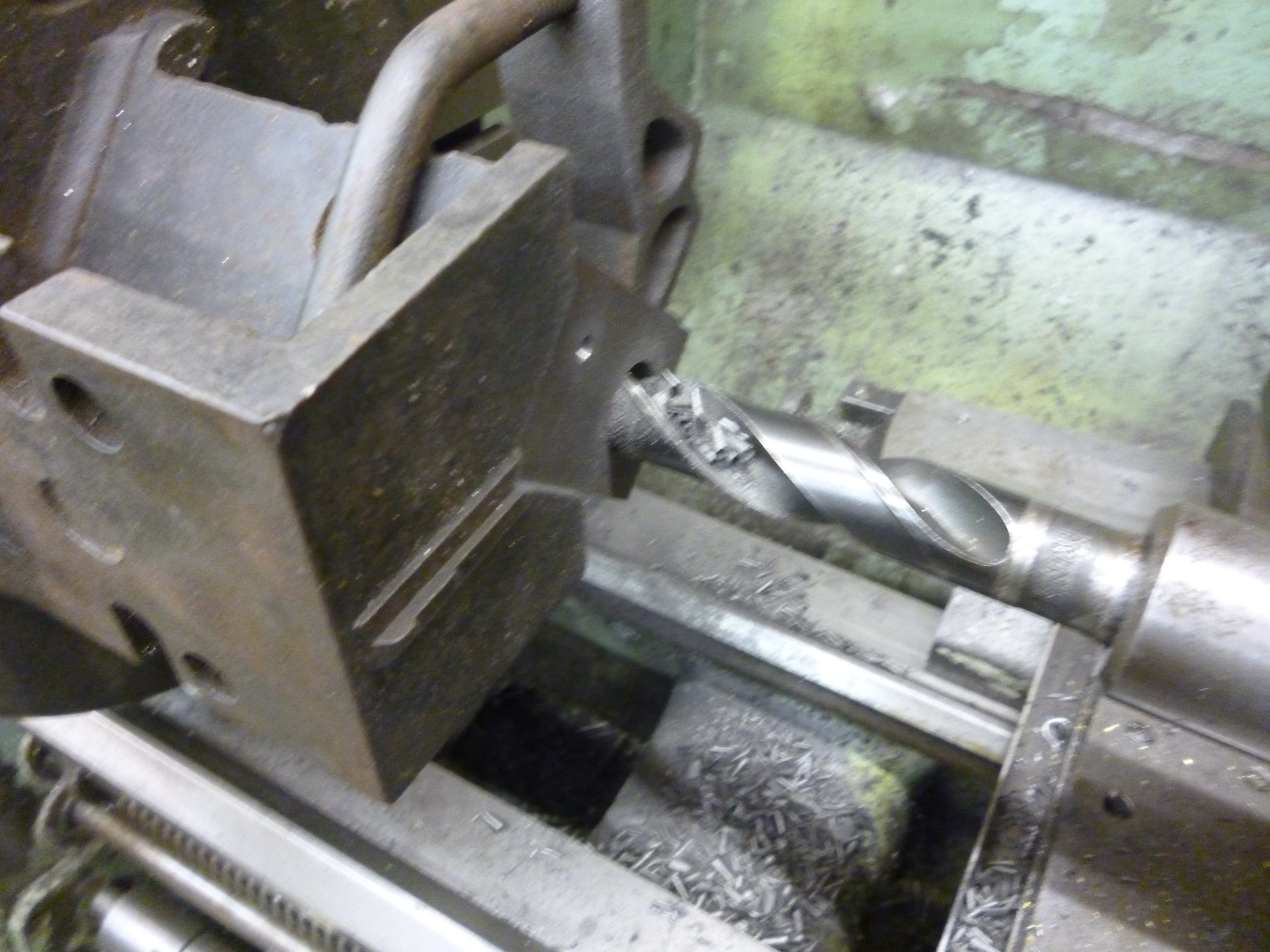
fig 2409
If the right size drill is not available then the hole can be bored. In fact it is even possible to produce the finished hole by boring. If this is done it is essential to make the last cut three times with the same setting of the cross slide.
Notice the workpiece is set so that it is possible to drill and or bore it all the way through.

fig 2411
Alternatively the hole can be reamed..
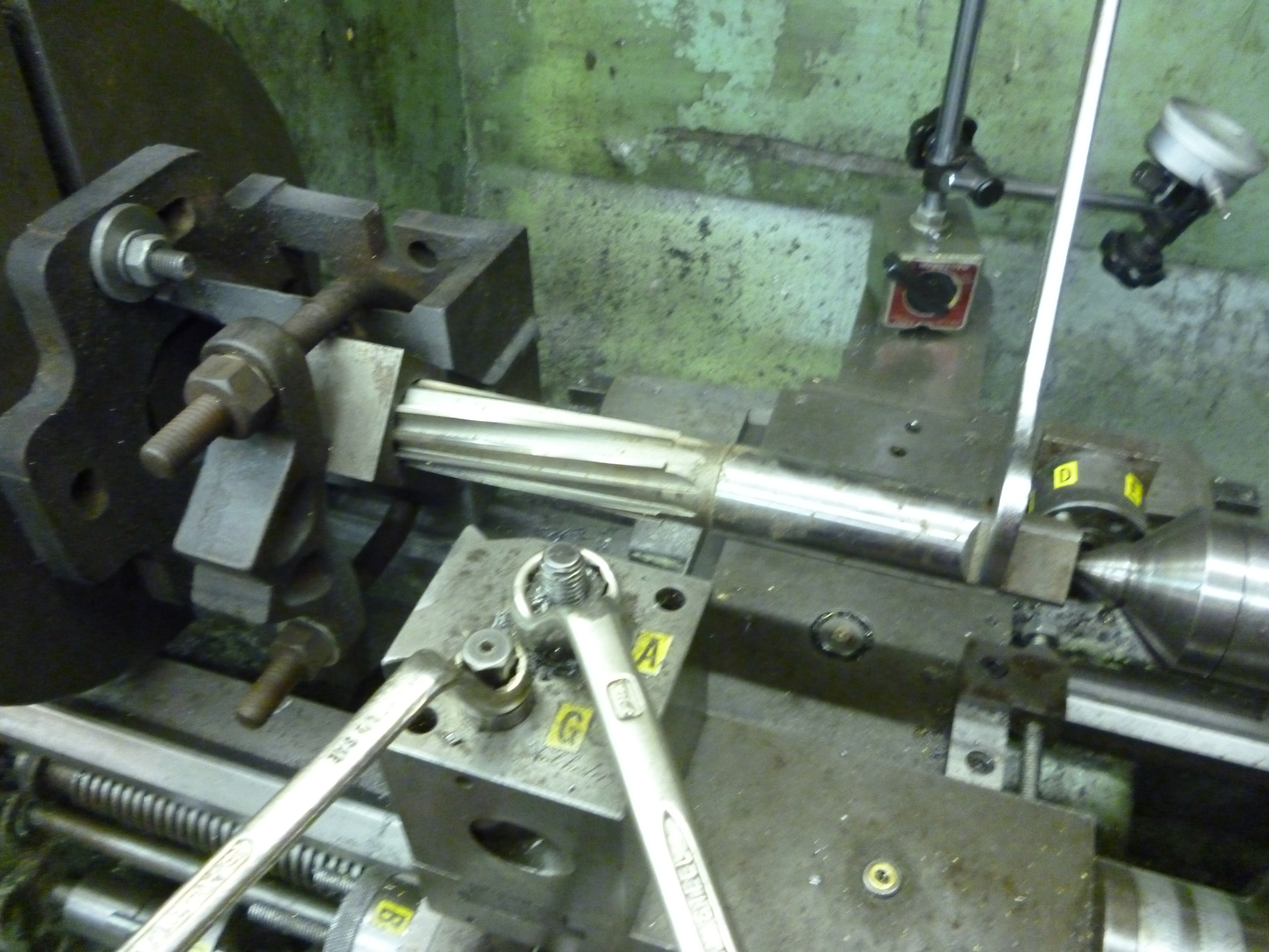
fig 2413
The whole process is now repeated for the hole for the liner for the valve piston.
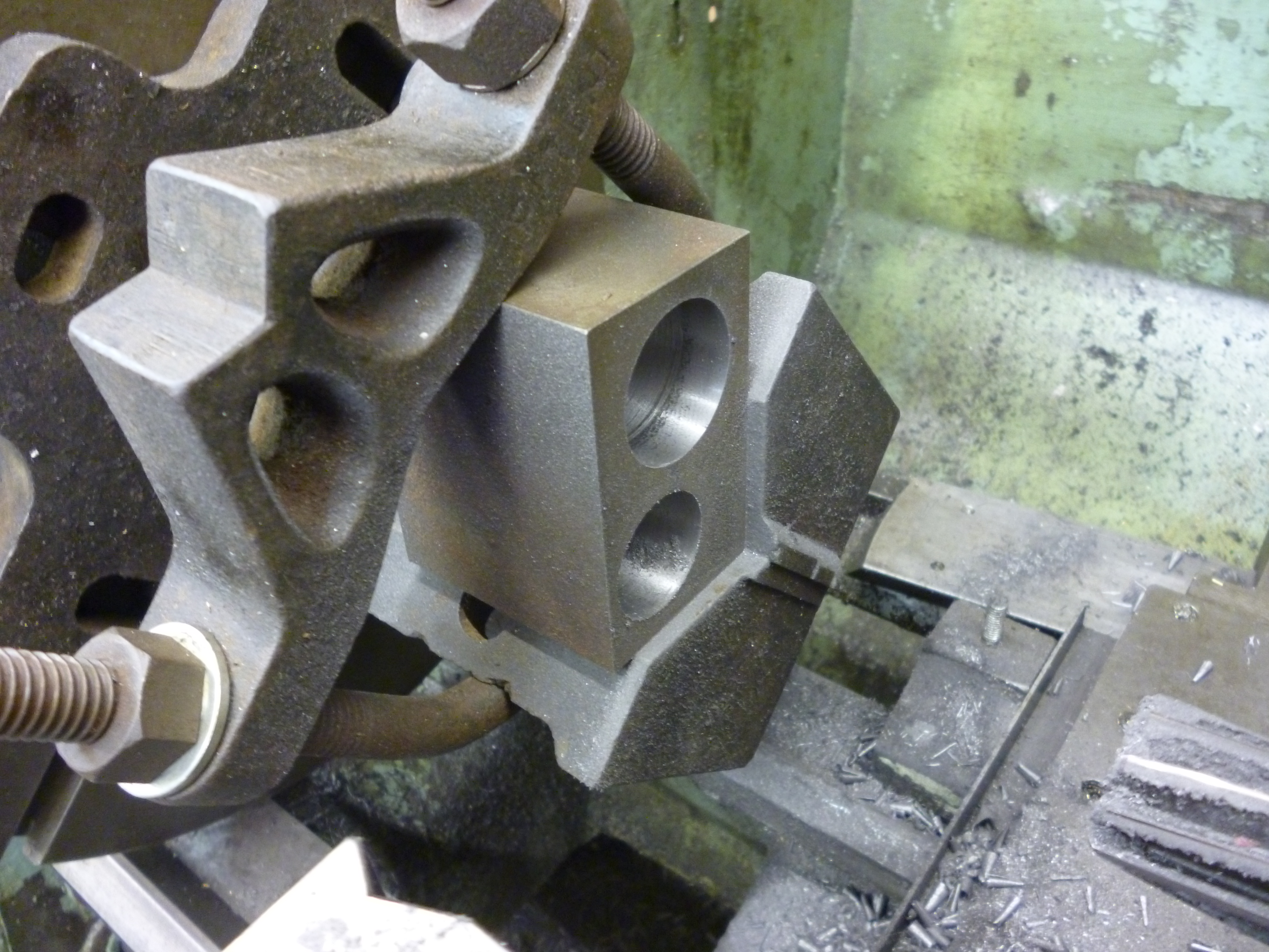
fig 2414
The cylinder block can now be removed from the Keats block.
Unless the lathe is perfectly set up it is possible for the hole to be slightly tapered. One way of improving this is to use a adjustable reamer. This is set up so it will on just go about 15mm at the wide end. This is because adjustable reamers have a leading taper which does not count towards the final size of the hole. This process is repeated till the hole is parallel.
