go to the page above
Making – Dickson type toolholders and toolposts
Use of words
Here the toolpost is the part that is fixed to the top slide by means of the toolpost stud. The toolpost then holds the toolholder.
Dickson toolholders and toolposts
One of the most popular types of tool post/toolholders is that made by Dickson.
fig Dickson toolholder/ toolpost
The key feature that makes this interesting is that the alignment between the tool holder and the tool post is done using two pairs of male V’s and female V’s.
Needless to say, the whole thing depends upon the both pair of V’s matching up perfectly in order that the tool will always be in the same place each time it is fitted to the toolpost.
In these examples a thin piece of metal is used instead of a piece that would be the height of the toolholder.
Making the female V’s
The workpiece is fitted parallel to the length of the milling table. The V-shaped cut is made using an ordinary end mill in a collet chuck in the vertical spindle of the milling machine. The vertical head is tilted at 45º. All of the cuts are made at the same height. One V is cut at an appropriate point on the workpiece. The DRO is set to zero at this point. After the first V has been cut the table is moved by the amount required between the first V and the second. The table is locked. The second cut is made.
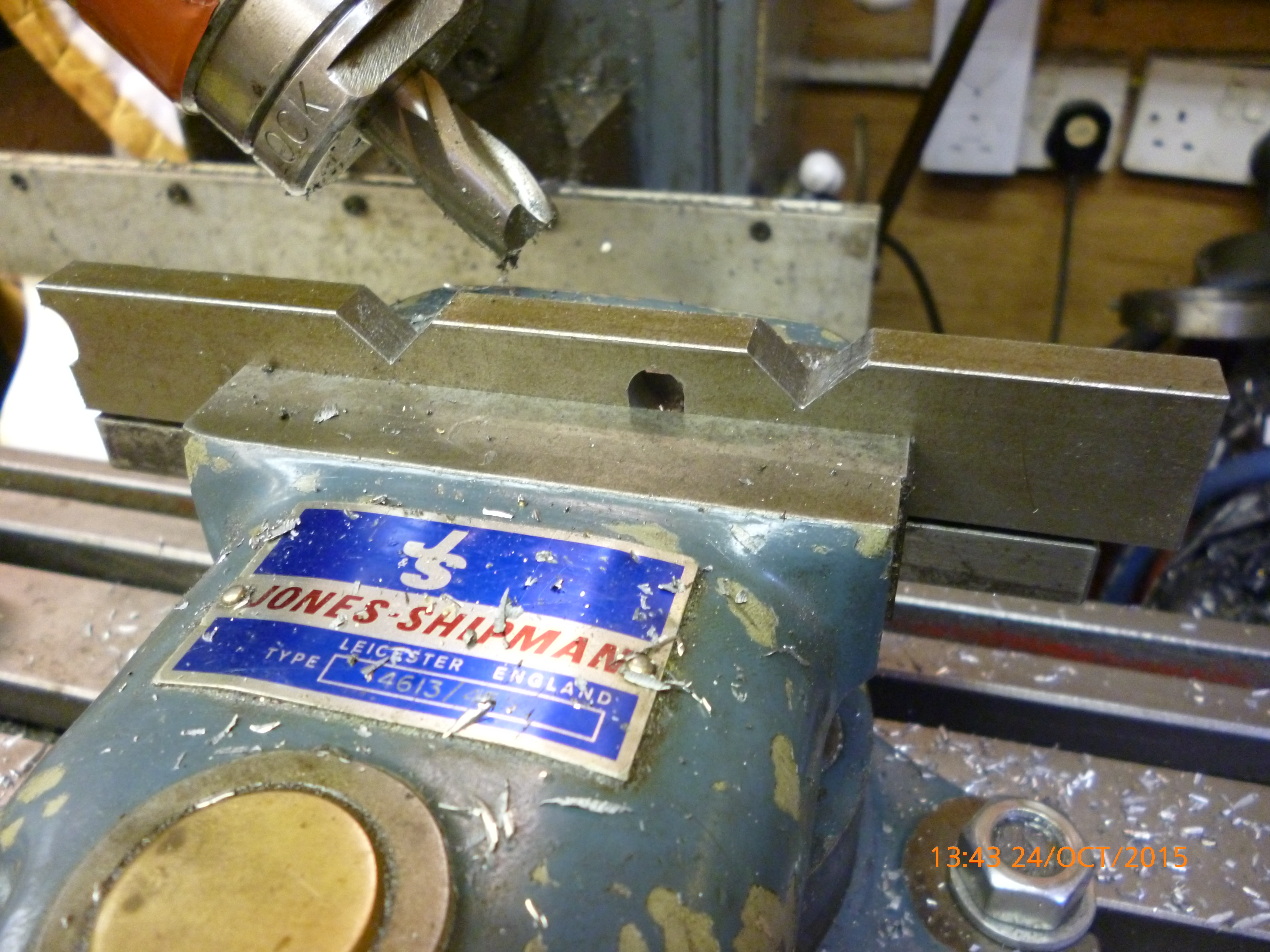
x3200 Dickson toolholder 1
fig first part with two female V’s
Making the male V’s
The part with male V’s is made by making two female V’s just as done on the other part as shown above.
The trick is that, for the male V’s, a a second pair of female V’s is made. The first of these is made just to one side of the first ones. This is done so the there is a small space, about 1mm on the top of the inverted V. Then the workpiece is moved along by the distance apart the same as for the female V’s. Notice that though a V is cut only one side of this will be used.
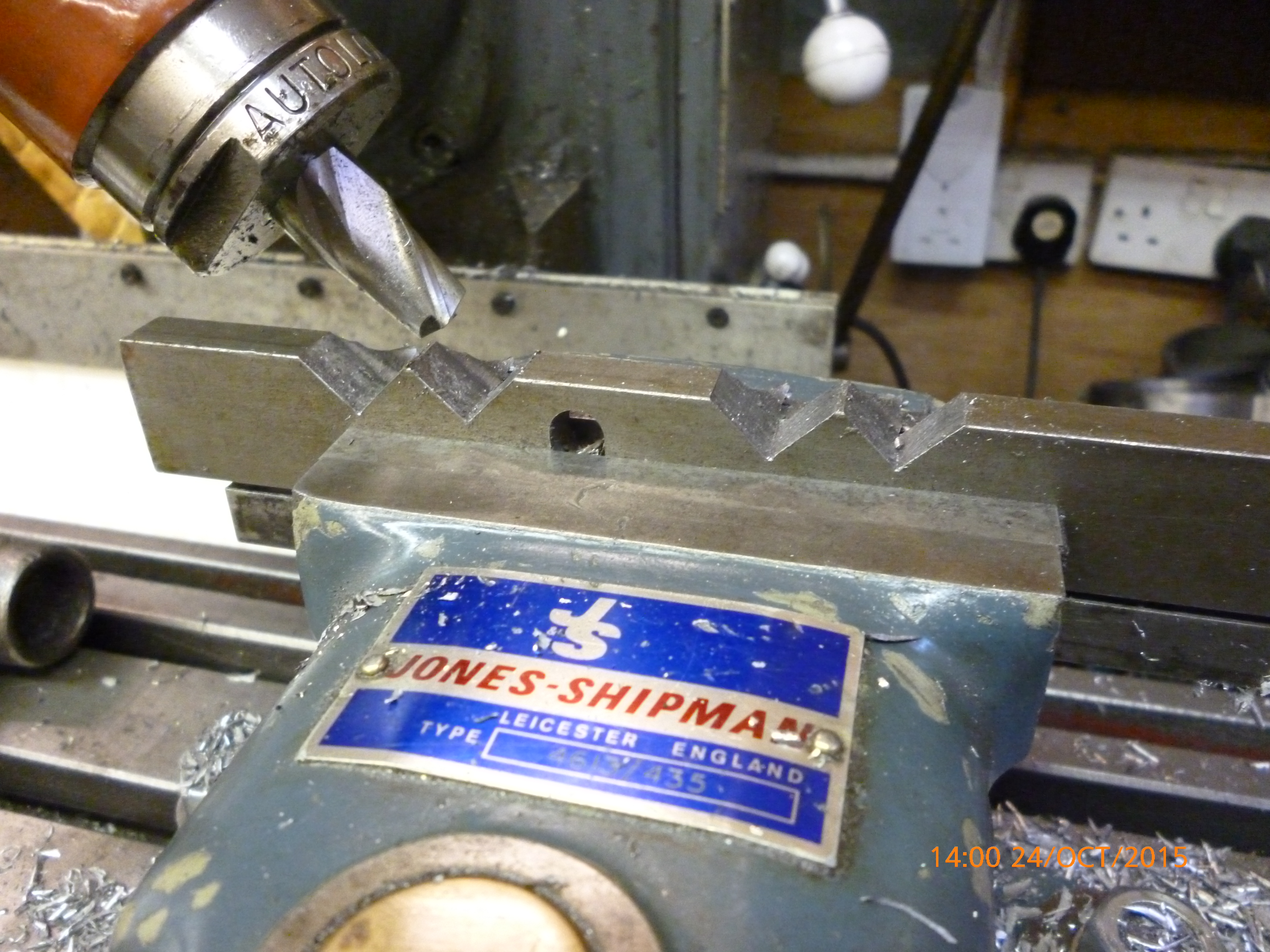
x3201 Dickson toolholder 2
fig two pairs of female V’s giving two inverted male V’s
All the material on either side of the male V’s is milled away.
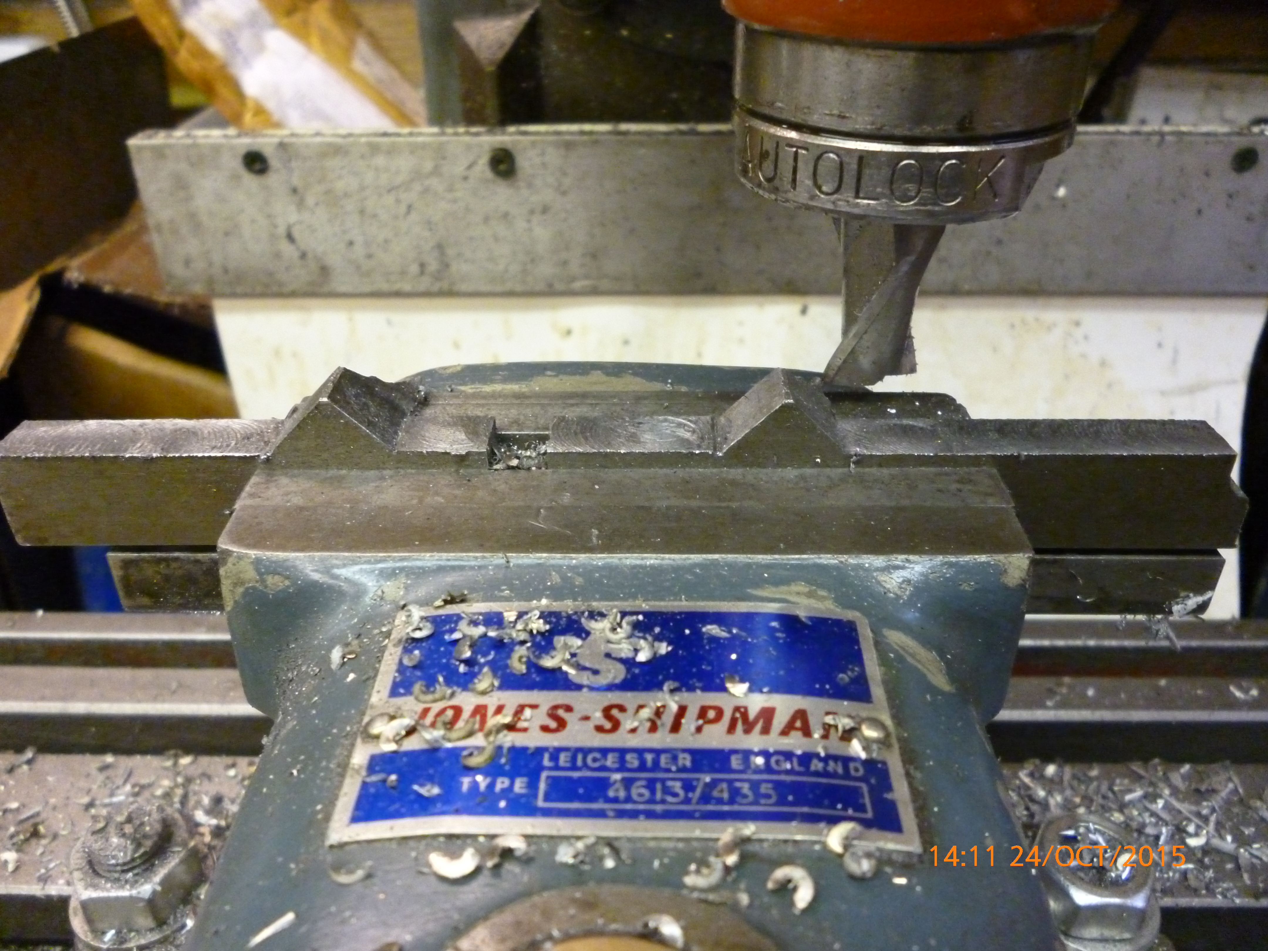
x3202 Dickson toolholder 3
fig milling the excess away
The two parts will now fit together. Notice that the top of the male V’s being flat means to the two parts do not clash at the apex of the V’s.
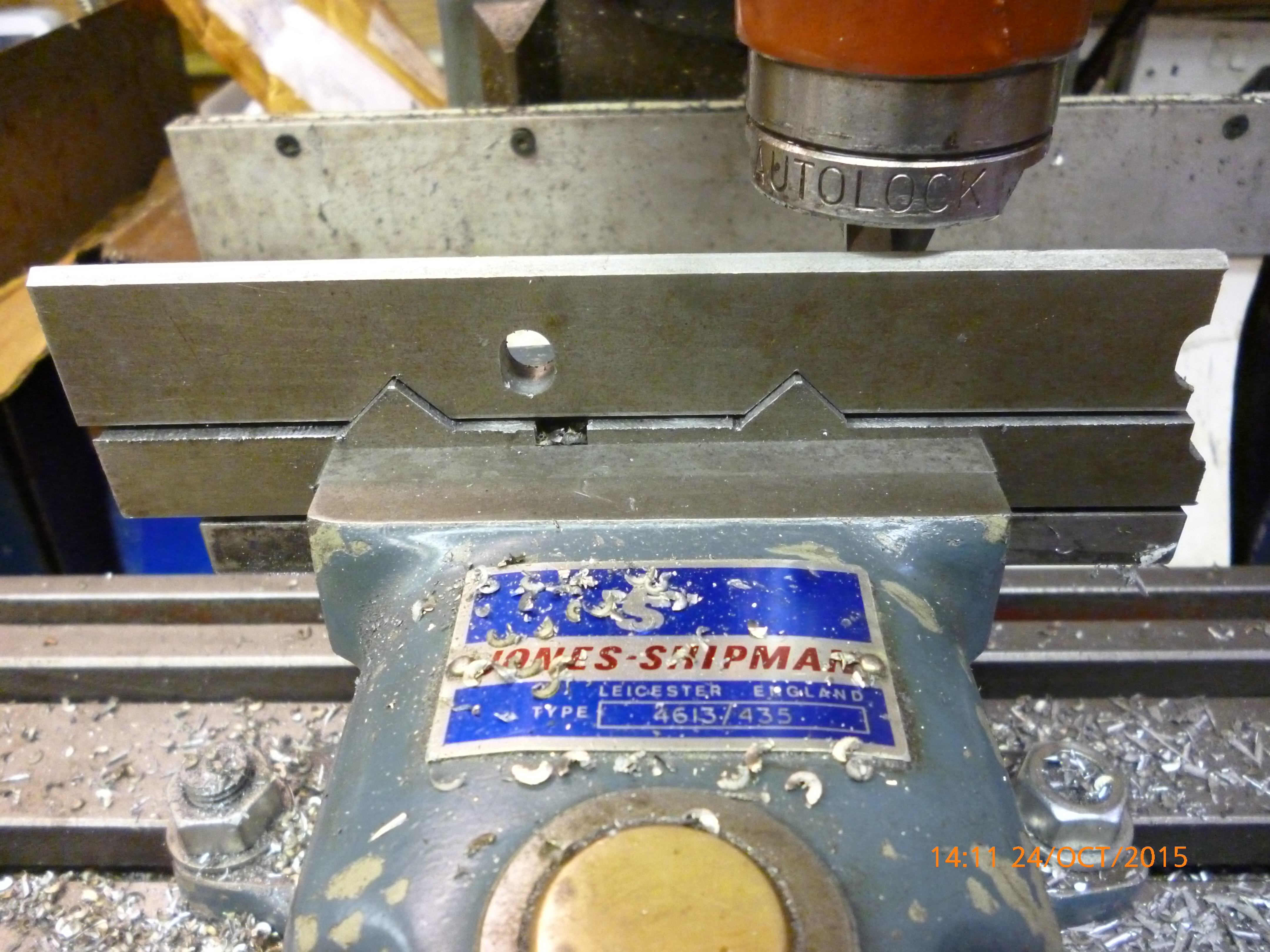
x3203 Dickson toolholder 4
On the Dickson toolpost/toolholder the only surfaces that are critical are those on the V’s as described above.
The T-slot, not shown here, is only required for effective clamping of the toolholder to the toolpost. But The thinness of the parts of the T are such that they are likely to break is made of cast iron. The toolholder must be made of steel though the toolpost could be made of steel or cast iron.
